RUF150701IntegrAlarm Control Panel
EMTS Inc.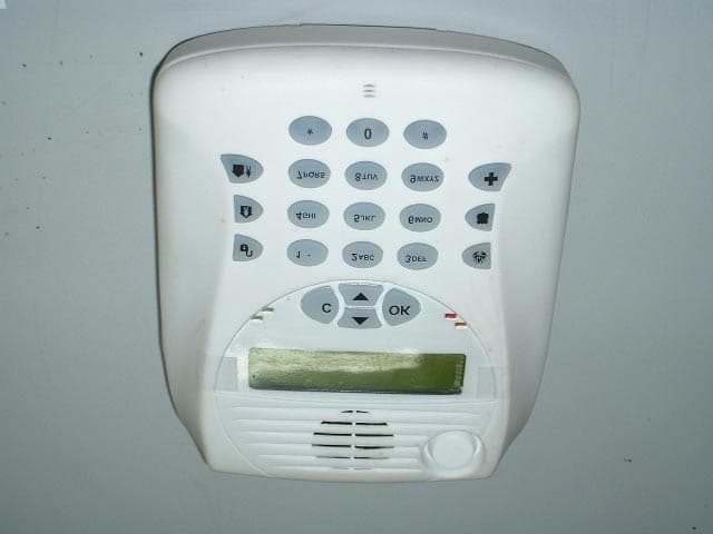
Click to zoom
Application Details
- Equipment Class
- DSS - Part 15 Spread Spectrum Transmitter
- Date of Grant
- Mar 20, 2004
- Application Purpose
- Original Equipment
- Date of Application
- Mar 20, 2004
- Equipment Note
- IntegrAlarm Control Panel
- Frequency Range
- 916.50000000 - 926.50000000
- Company
- EMTS Inc.
- Country
- Canada
Documents & Files
Document Text
Text extracted from the exhibit documents filed with the FCC. Open a document above to read the original.
Users Manual
Page 1 of 67 pages Document # E.0015.16.03 406984 IntegrAlarm IA-1000 WIRELESS SECURITY SYSTEM INSTALLER MANUAL February 2004 Page 2 of 67 pages Document # E.0015.16.03 406984 Table of Contents 1 Control Panel Description.................................................................. 4 1.1 FCC Compliance & Statements........................................................ 5 1.1.1 FCC Part 15 Compliance Statement................................................ 5 The FCC Wants You to Know........................................................................... 5 FCC ID: RUF150704.......................................................................................... 5 FCC Warning....................................................................................................... 6 1.1.2 FCC Part 68 Statements.................................................................... 7 2 Installation Procedure....................................................................... 12 2.1 Battery Installation............................................................................ 12 2.2 RJ31X Connector.............................................................................. 12 2.3 Connectors J5 and J7...................................................................... 12 2.4 Connector J9 (Terminal Block)........................................................ 13 3 Programming Procedure.................................................................. 14 3.1 General............................................................................................... 14 3.2 Installer Programming Functions.................................................... 14 3.2.1 Zone Options..................................................................................... 15 3.2.2 Timers & Counter.............................................................................. 25 3.2.3 System Options................................................................................. 28 3.2.4 Access Codes.................................................................................... 36 3.2.5 Output Options.................................................................................. 37 3.2.6 X-10 Options...................................................................................... 40 3.2.7 Communications Options................................................................ 44 3.2.8 Report Codes..................................................................................... 52 3.2.9 Download Options............................................................................. 59 Page 3 of 67 pages Document # E.0015.16.03 406984 3.2.10 Enroll Zones....................................................................................... 62 3.2.11 Place Test........................................................................................... 63 3.2.12 Others................................................................................................. 64 3.2.13 Saving Data........................................................................................ 67 Page 4 of 67 pages Document # E.0015.16.03 406984 1 Control Panel Description The Control Panel consists of an RF transceiver, a micro-controller, a non-volatile memory, a power supply, a user interface, a siren, a buzzer, a tamper switch and a battery. The Control Panel is composed of the following principal parts: • Mounting plate. • Control Panel unit with keypad, display, electronic assembly, siren, speaker, microphone, 4 LEDs and battery compartment. • 6 NiCd size AA batteries. • Wall mounted AC adapter (120 VAC to 9 VAC insulation transformer) The complete Control Panel and keyboard and an exploded view of the Control Panel are shown below. Page 5 of 67 pages Document # E.0015.16.03 406984 1.1 FCC Compliance & Statements 1.1.1 FCC Part 15 Compliance Statement The FCC Wants You to Know This equipment has been tested and found to comply with the limits for a Class B digital device, pursuant to Part 15 of the FCC rules. These limits are designed to provide reasonable protection against harmful interference in a residential installation. This equipment generates, uses and can radiate radio frequency energy and, if not installed and used in accordance with the instructions, may cause harmful interference to radio communications. However, there is no guarantee that interference will not occur in a particular installation. If this equipment does cause harmful interference to radio or television reception, which can be determined by turning the equipment off and on, the user is encouraged to try to correct the interference by one or more of the following measures: a) Reorient or relocate the receiving antenna. b) Increase the separation between the equipment and receiver. c) Connect the equipment to an outlet on a circuit different from that to which the receiver is connected. d) Consult the dealer or an experienced radio technician. FCC ID: RUF150704 This device complies with Part 15 of the FCC Rules. Operation is subject to the following two conditions: (1) This device may not cause harmful interference and Page 6 of 67 pages Document # E.0015.16.03 406984 (2) This device must accept any interference received, including interference that may cause undesired operation. FCC Warning Modifications not expressly approved by the manufacturer could void the user authority to operate the equipment under FCC Rules. Instructions concerning human exposure to radio frequency electromagnetic fields. To comply with FCC Section 1.307 (b)(1) for human exposure to radio frequency electromagnetic fields, implement the following instruction: A distance of at least 20cm. between the equipment and all persons should be maintained during the operation of the equipment. Page 7 of 67 pages Document # E.0015.16.03 406984 1.1.2 FCC Part 68 Statements a. This equipment complies with Part 68 of the FCC rules and requirements adopted by ACTA. On the bo…
Text truncated - open the document above for the full version.
Users Manual
Page 1 of 46 Document # E.0015.16.02 406985 IntegrAlarm IA-1000 WIRELESS SECURITY SYSTEM CONTROL PANEL MODEL IA-CP1 USER GUIDE February 2004 Page 2 of 46 Document # E.0015.16.02 406985 Page 3 of 46 Document # E.0015.16.02 406985 Table of Contents General ........................................................................................................................... 4 1.1 IntegrAlarm Wireless Alarm System Overview....................................4 1.2 Security Characteristics......................................................................5 1.3 Wireless Specifications......................................................................6 1.4 General Specifications.......................................................................7 2 FCC Compliance & Statements.................................................................. 8 2.1 FCC Part 15 Compliance Statement....................................................8 2.2 FCC Part 68 Statements...................................................................10 3 System Operation ..................................................................................... 12 3.1 Glossary of Terms...........................................................................12 3.2 Control Panel Layout.......................................................................14 3.3 Arming / Disarming the System........................................................17 3.4 Numeric Keypad Shortcut Functions.................................................25 3.5 Additional User Functions................................................................28 3.6 Master Functions.............................................................................35 Page 4 of 46 Document # E.0015.16.02 406985 General 1.1 IntegrAlarm Wireless Alarm System Overview The IntegrAlarm wireless security system consisting of a Control Panel and a number of wireless peripheral units. This is a two way system operating on the ISM wireless band of 902-928 MHz, in frequency hopping mode, transmitting short (about 10 ms) packets of data, with each packet transmitted on a different frequency. Every packet is validated by means of a 16 bits CRC and ARQ (Autometic Repeat Request) ensure a new concept of reliability in wireless security systems. Time and frequency synchronization is maintained by a synchronization signal transmitted by the system Control Panel to the various peripherals every 3 minutes. The system operates on 56 pseudo random selected channels. The IntegrAlarm Control Panel includes a digital communicator for reporting of events to the Central Station and a voice communicator for reporting of events to up to six regular PSTN subscribers. The IntegrAlarm System offers several options for access to the operational system functions: • By means of the control panel keypad and display. • By means of a hand-held remote control (with up to five functions). • By means of any local or remote PSTN telephone. • By means of a local PC. • By means of a remote PC. Voice guidance and voice help (optional dual-language) ensure ease of system operation in all access options listed above. A voice mailbox is also available. The IntegrAlarm is designed for easy and quick installation; it can be programmed by any person with minimal computer skills, on a local PC with IntegrAlarm programming software. The system can also be installed and programmed by means of the Control Panel keypad and display. Page 5 of 46 Document # E.0015.16.02 406985 Technical assistance for installation and programming can be obtained from the Central Station service provider or the EMTS company web site. Upload/download of the complete Control Panel setup may be implemented by the Central Station or by a PC with the IntegrAlarm software package. In its present configuration, the system includes five types of peripheral units: Door / window sensor IntegrAlarm model IA-DWC1. PIR sensor IntegrAlarm model IA-PIR1. Smoke detector IntegrAlarm model IA-SMK1. Handheld 5 functions keyfob IntegrAlarm model IA-FOB1. Remote siren IntegrAlarm model IA-SRN1. Installation instructions for the IntegrAlarm peripherals appear in the User and Installer Manuals for the respective units. 1.2 Security Characteristics • Up to 64 distinct wireless zones (sensors) and 1 wired zone: Each zone is identified by number and name (zone names are assigned by installer). • Multiple arming modes: AWAY, HOME, AWAY-INSTANT, HOME-INSTANT and LATCHKEY. • Reporting destinations: Events of each category (panic, fire, medical, burglary, alert, arrival) are reported automatically to the central monitoring station. • The IntegrAlarm can be accessed from a remote telephone, to arm or disarm the system and receive system status information. • Voice guidance: Users are guided by pre-recorded announcements and instructions, heard via the control panel speaker or a remote telephone. Page 6 of 46 Document # E.0015.16.02 406985 • Message exchange: Short verbal messages may be recorded by any user. On arrival, each user can automatically receive any messages left for him. Messages may also be collected by remote telephone. • Electrical device control: X-10 modules can be programmed to control specific lights/appliances within the building. • Remote control from control panel, keyfob or telephone: PGM (programmable) modules can be used to control gate mechanisms, courtesy lighting and other devices outside the building. • A DAA (Direct Access Arrangement) with capacitive coupling to a DSP provide all PSTN functions including all pulse, DTMF and FSK communication protocols. A 2400 baud fast data transfer modem for remote programming. The DSP includes Telephone Line Monitor (TLM) that monitors continuously the status of the PSTN line. • Fully programmable control panel for a wide range of security options. The IntegrAlarm control panel meets the following SIA standards: • ANSI/SIA CP-01-2000 Control Panel standard – False Alarm Reduction Feature Standa…
Text truncated - open the document above for the full version.
External Photos
External Photographs Figure 1 Front View Figure 2 Rear View With Battery Cover Closed Figure 3 Rear View With Battery Cover Open
ID Label/Location Info
IA-CP1 Control panel Labels Size and location 180 mm 220 mm Part 15 label Product label Labels location: on the product back cover between the back cover and the mounting bracket Product label 30 mm 20 mm IntegrAlarm Control panel Model IA-CP1 S/N xxxxxxxx FCC Part 15 label 50 mm 25 mm FCC ID: RUF150701IC:4937A-150701 This device complies with Part 15 of the FCC rules. Operation is subject to the following two conditions: (1)This device may not cause harmful interference and (2) This device must accept any interference received, including interference that may cause undesired operation. This device meets the requirements of 47 CFR, Part 68. Product ID:IA-CP1 REN:0.1B Ringer Type:B Registration #: US: AAAEQ##TXXXX Canadian registration #: IC:4937A-IACP1 REN:0.1A Ringer Type:A Wiring label External connections recess 42.5 mm Part 68 label FCC Part 68 label
Internal Photos
Internal Photographs Figure 1 PCB 1 in Unit Figure 2 PCB 1 Side 1 Without Batteries Figure 3 PCB 1 Side 2 Figure 4 PCB 1 Side 2 Without Shield Figure 5 PCB 2 in Unit Figure 6 PCB 2 Side 1 Figure 7 PCB 2 Side 2 With Cover (Buttons) Figure 8 PCB Side 2 PCB 2 Side 2 Without Cover (Buttons)
Test Report
Cert. No. 1152.01 Electrical (EMC) Test Report E52237.00 EMTS Inc. Page 1 of 63 FCC ACC M Ver 1.1 05Mayl 2000 DATE: 02 March 2004 I.T.L. (PRODUCT TESTING) LTD. FCC EMC Test for EMTS Inc. Equipment under test: IntegrAlarm Control Panel (Transmitter Section) IA-CP1 Approved by: _____________________________ I. Raz, EMC Laboratory Manager This report must not be reproduced, except in full, without the written permission of I.T.L. (Product Testing) Ltd. This report relates only to items tested. Cert. No. 1152.01 Electrical (EMC) Test Report E52237.00 EMTS Inc. Page 2 of 63 FCC ACC M Ver 1.1 05Mayl 2000 Measurement/Technical Report for EMTS Inc. IntegrAlarm Control Panel (For Transmitter Section) IA-CP1 FCC ID:RUF150701 02 March 2004 This report concerns: Original Grant x Class II change Class B verification Class A verification Class I change Equipment type: Radio Telemetry Transmitter Request Issue of Grant: x Immediately upon completion of review Limits used: CISPR 22 Part 15 x Measurement procedure used is ANSI C63.4-2001. Application for Certification Applicant for this device: prepared by: (different from "prepared by") Ishaishou Raz Doron Lavee ITL (Product Testing) Ltd. EMTS Inc. Kfar Bin Nun 300 Alden Road D.N. Shimshon 99780 Markham, Ontario, L3R4C1 Israel Canada e-mail [email protected] Tel: +1-905-946-8589 Fax: +1-905-947-0138 e-mail: [email protected] Test Report E52237.00 EMTS Inc. Page 3 of 63 FCC ACC M Ver 1.1 05Mayl 2000 TABLE OF CONTENTS 1. GENERAL INFORMATION ------------------------------------------------------------------------------- 5 1.1 Administrative Information.................................................................................5 1.2 List of Accreditations .........................................................................................6 1.3 Product Description ...........................................................................................7 1.4 Test Methodology..............................................................................................8 1.5 Test Facility .......................................................................................................9 1.6 Measurement Uncertainty .................................................................................9 2. PRODUCT LABELING -----------------------------------------------------------------------------------10 3. SYSTEM TEST CONFIGURATION--------------------------------------------------------------------11 3.1 Justification......................................................................................................11 3.2 EUT Exercise Software ...................................................................................12 3.3 Special Accessories ........................................................................................12 3.4 Equipment Modifications .................................................................................12 3.5 Configuration of Tested System ......................................................................12 4. BLOCK DIAGRAM-----------------------------------------------------------------------------------------13 4.1 Schematic Block/Connection Diagram............................................................13 4.2 Theory of Operation ........................................................................................13 5. CONDUCTED AND RADIATED MEASUREMENT PHOTOS ----------------------------------14 6. CONDUCTED EMISSION DATA-----------------------------------------------------------------------17 6.1 Test Specification ............................................................................................17 6.2 Test Procedure................................................................................................17 6.3 Measured Data................................................................................................17 6.4 Test Instrumentation Used, Conducted Measurement ...................................20 7. CUSTOMER’S DECLARATION ------------------------------------------------------------------------21 8. SPURIOUS RADIATED EMISSION, BELOW 1 GHZ---------------------------------------------22 8.1 Test Specification ............................................................................................22 8.2 Test Procedure................................................................................................22 8.3 Test Data .........................................................................................................23 8.4 Test Instrumentation Used, Radiated Measurements ....................................25 8.5 Field Strength Calculation ...............................................................................26 9. SPURIOUS RADIATED EMISSION ABOVE 1 GHZ ----------------------------------------------27 9.1 Test Specification ............................................................................................27 9.2 Radiated Emission Above 1 GHz....................................................................27 9.3 Test Data .........................................................................................................27 9.4 Test Instrumentation Used, Radiated Measurements Above 1 GHz ..............36 10. MAXIMUM TRANSMITTED PEAK POWER OUTPUT -------------------------------------------37 10.1 Test procedure ................................................................................................37 10.2 Results table....................................................................................................38 10.3 Test Equipment Used......................................................................................39 11. PEAK POWER OUTPUT OUT OF 902-928 MHZ BAND ----------------------------------------40 11.1 Test procedure ................................................................................................40 11.2 Results table...................................................................…
Text truncated - open the document above for the full version.
Test Report
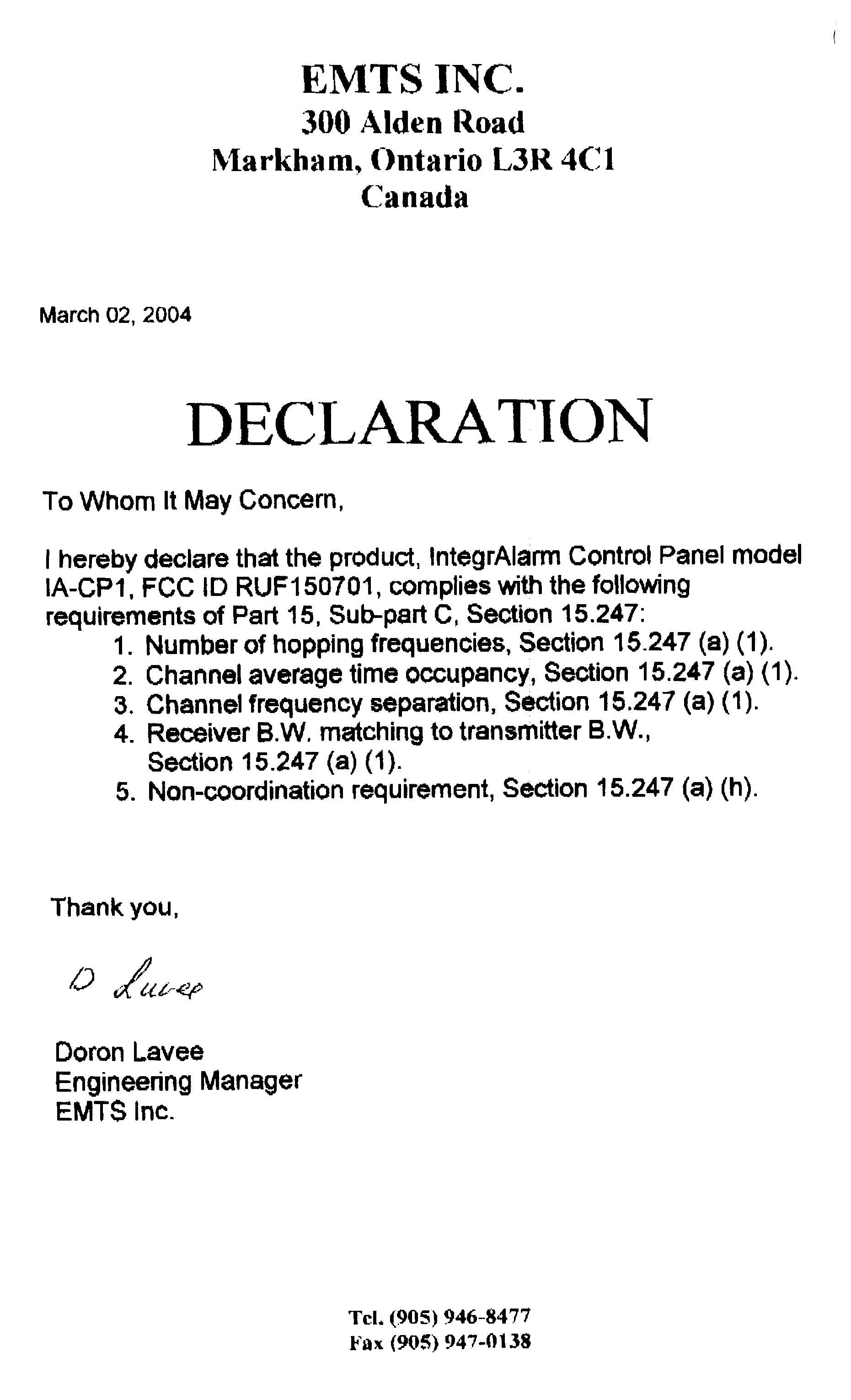
Chris Harvey From: EMC [[email protected]] Sent: Monday, March 15, 2004 12:46 AM To: Chris Harvey Subject: RE: Confirmation for 15.247 of FCC ID:RMZ150701 MT#15236 Page 1 of 1 3/15/2004 Sorry Chris, My mistake. I accidentally put the wrong declaration in the report. Attached is the correct declaration for the subject application. Regards David Shidlowsky Technical Writer EMC Laboratory ITL (Product Testing) Ltd. Kfar Bin Nun Israel Tel: +972-8-9797799 Fax: +972-8-9797702 Email: [email protected] http://www.itl.co.il http://www.i-spec.com This e-mail message may contain privileged or confidential information. If you are not the intended recipient, you may not disclose, use, disseminate, distribute, copy or rely upon this message or attachment in any way. If you received this e-mail message in error, please return by forwarding the message and its attachments to the sender. -----Original Message----- From: Chris Harvey [mailto:[email protected]] Sent: Sunday, March 14, 2004 3:29 PM To: Shaike Raz; EMC Cc: 'Marianne Bosley' Subject: Confirmation for 15.247 of FCC ID:RMZ150701 MT#15236 Shaike or David, please respond to the following request as I could not find the information in the application documentation: 1. Does the frequency hopping system comply with the non-coordination requirement of 15.247(h)? 2. Does this transmitter use equally on average each of the transmitter frequencies to comply with the requirement of FCC 15.247(a)(1)? Best regards, Chris Harvey
Contact Information
Applicant
Joel Kligman
Test Firm
ITL Product Testing LTDSteli Loznen
Technical Specifications
| # | Rule Parts | Frequency Range | Power Output |
|---|---|---|---|
| 1 | 15C | 916.5 MHz - 926.5 MHz | 14.00 mW |
Other Applications from EMTS Inc.
RUF150706
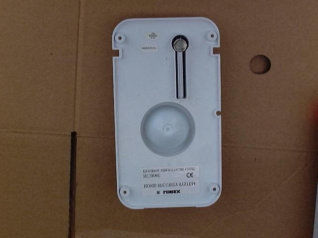
Jun 22, 2004IntegrAlarm Remote Siren/Strobe
Equipment Class
DSS - Part 15 Spread Spectrum Transmitter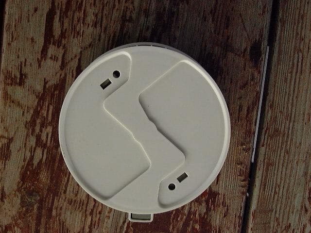
RUF150705
Feb 29, 2004Integr Alarm Wireless Smoke Detector
Equipment Class
DSS - Part 15 Spread Spectrum Transmitter
RUF150704
Feb 11, 2004Door/Window Sensor
Equipment Class
DSS - Part 15 Spread Spectrum Transmitter
RUF150702
Feb 11, 20045-Function Key Fob
Equipment Class
DSS - Part 15 Spread Spectrum Transmitter
RUF150703
Feb 11, 2004Passive Infra Red Motion Detector
Equipment Class
DSS - Part 15 Spread Spectrum Transmitter