RUF150703Passive Infra Red Motion Detector
EMTS Inc.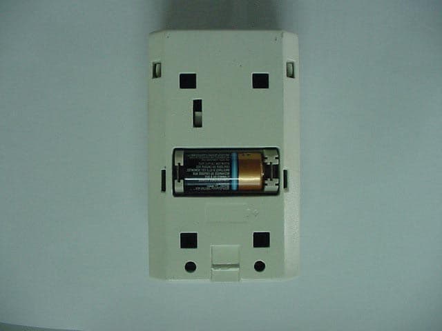
Click to zoom
Application Details
- Equipment Class
- DSS - Part 15 Spread Spectrum Transmitter
- Date of Grant
- Feb 11, 2004
- Application Purpose
- Original Equipment
- Date of Application
- Feb 11, 2004
- Equipment Note
- Passive Infra Red Motion Detector
- Frequency Range
- 903.50000000 - 913.50000000
- Company
- EMTS Inc.
- Country
- Canada
Documents & Files
Document Text
Text extracted from the exhibit documents filed with the FCC. Open a document above to read the original.
Users Manual
Document # E.0015.16.06 396251 IntegrAlarm USER AND INSTALLER MANUAL (PASSIVE INFRARED DETECTOR) IntegrAlarm MODEL IA-PIR 1 February 09, 2004 Document # E.0015.16.06 396251 Table of Contents 1 IntegrAlarm Overview..........................................................................3 2 Passive Infrared Detector...................................................................5 2.1 Description............................................................................................5 2.2 Technical Specifications......................................................................5 2.3 Installation.............................................................................................9 2.3.1 Registration...........................................................................................9 2.3.2 Mounting................................................................................................9 2.3.3 Te s t i n g..................................................................................................10 Document # E.0015.16.06 396251 1 IntegrAlarm Overview The IntegrAlarm wireless security system includes a Control Panel and a number of wireless peripheral units. The system operates on the ISM wireless band of 902-928 MHz, in frequency hopping mode, transmitting short (about 10 ms) packets of data, with each packet transmitted on a different frequency. Time and frequency synchronization is maintained by a synchronization signal transmitted by the system Control Panel to the various peripherals (including the IA-PIR 1) every 3 minutes. The system operates on 56 pseudo random selected channels. In its present configuration, the system includes five types of peripheral units: • Door / window sensor. • Passive infrared detector. • Smoke detector. • Handheld remote control. • Remote siren. This manual is devoted to the installation instructions for the IntegrAlarm IA-PIR 1 passive infrared detector. The installation instructions for the other IntegrAlarm peripherals and the IntegrAlarm Control Panel appear in the User and Installer Manuals for the respective units. Document # E.0015.16.06 396251 FCC Compliance Statement The FCC Wants You to Know This equipment has been tested and found to comply with the limits for a Class B digital device, pursuant to Part 15 of the FCC rules. These limits are designed to provide reasonable protection against harmful interference in a residential installation. This equipment generates, uses and can radiate radio frequency energy and, if not installed and used in accordance with the instructions, may cause harmful interference to radio communications. However, there is no guarantee that interference will not occur in a particular installation. If this equipment does cause harmful interference to radio or television reception, which can be determined by turning the equipment off and on, the user is encouraged to try to correct the interference by one or more of the following measures: a) Reorient or relocate the receiving antenna. b) Increase the separation between the equipment and receiver. c) Connect the equipment to an outlet on a circuit different from that to which the receiver is connected. d) Consult the dealer or an experienced radio technician. FCC ID: RUF150703 This device complies with Part 15 of the FCC Rules. Operation is subject to the following two conditions: (1) This device may not cause harmful interference and (2) This device must accept any interference received, including interference that may cause undesired operation. FCC Warning Modifications not expressly approved by the manufacturer could void the user authority to operate the equipment under FCC Rules. Instructions concerning human exposure to radio frequency electromagnetic fields. To comply with FCC Section 1.307 (b)(1) for human exposure to radio frequency electromagnetic fields, implement the following instruction: A distance of at least 20cm. between the equipment and all persons should be maintained during the operation of the equipment. Document # E.0015.16.06 396251 2 Passive Infrared Detector 2.1 Description The PIR detector unit consists of a PIR sensor and circuitry, an RF transceiver, a micro- controller, a non-volatile memory, a power supply, a tamper switch, a test switch and a 3V Lithium HNO 2 battery type 123. The sensor unit is composed of the following principal parts: • Mounting plate. • Sensor PCB assembly with RF controller PCB, LED and battery. • Inner cover. • Outer cover with IR motion lens. An exploded view of the PIR sensor unit is shown in Figure 1 below. To reduce false alarms, the PIR is pet-immune and has a selectable alarm threshold (1, 2 or 3 movements in the protected space). Once an alarm has been transmitted, the PIR shuts down for a minimum of 2 minutes. After 2 minutes, the PIR will automatically be rearmed, provided that movement within the protected space has ceased and not resumed. Depending on the space to be protected, the PIR has either a wide-angle lens, with a 70° viewing angle and a maximum range of 15 m, or a long-range lens, with a 9° viewing angle and a maximum range of 21 m. (The standard lens supplied is the wide-angle lens.) A diagram of the lens coverage appears in Figure 2 below. 2.2 Technical Specifications Operating frequency band – ISM 902-928 MHz. Mode of operation – frequency hopping; every data packet is transmitted on a different pseudo random selected frequency. Data packet transmission duration – less than 7 milliseconds. Data packet validity check – CRC. Transmission and reception verification – two-way communication; each received packet is acknowledged, with an automatic repeat request (ARQ) in case of unacknowledged data packet. IR detector sensitivity – ∆ 1.6 deg. @ 0.6 m/sec. Movement speed range – 0.3 to 1.5 m/sec. Detection field of view @ maximum range with WA lens – 21 m @ 15 m range *. Detection field of view @ maximum range with LR lens – 3.5 m @ 21 m range *. Events reported – mov…
Text truncated - open the document above for the full version.
External Photos
External Photographs of Tested E.U.T. Figure 1 Front View Figure 2 Rear View With Wall Mounting Assembly Figure 3 Wall Mounting Assembly Figure 4 Rear View Battery Cover Removed
ID Label/Location Info
IA-PIR1 Passive Infra-red Motion Detector Labels Size and location Labels location: on the product back cover, between the back cover and the mounting bracket 65 mm 108 mm FCC ID: RUF150703 30 mm 20 mm IntegrAlarm Passive Infra-red Motion Detector Model IA-PIR1 S/N xxxxxxxx Product label FCC ID: RUF150703 12 mm 40 mm FCC ID embossed in housing plastic material IntegrAlarm Passive Infra-red Motion Detector Model IA-PIR1 S/N xxxxxxxx
Internal Photos
Internal Photos Figure 1 Front Cover Internal View Figure 2 PCB in Unit Figure 3 PCB Side 1 Figure 4 PCB Side 1 Shield Removed Figure 5 PCB Side 1 Area Under Shield Figure 6 PCB Side 2
Test Report
Close From: EMC [SMTP:[email protected]] To: Chris Harvey (E-mail 3) Cc: Doron Lavee (E-mail); Marianne Bosley (E-mail); Len Knight (E-mail) Subject: ITL Applications for MT#14925; MT#14926; MT#14927 Sent: 1/15/2004 6:05 AM Importance: Normal Ref: You emails of 14 January 2004 Hi Chris, 1. Thank you for your prompt responses. 2. Concerning your comment to all 3 applications: " This device is a composite device with a transmitter and receiver contained... FCC requirements for a receiver" please be advised: 2.1. We tested separately all the receivers to Sub-part B. 2.2. The receiver frequency range of operation is 916.5MHz to 926.5MHz. 3. We will respond to all your other comments shortly. Regards Shaike Raz EMC Laboratory Manager EMC Laboratory ITL (Product Testing) Ltd. Kfar Bin Nun Israel Tel: +972-8-9797799 Fax: +972-8-9797702 Email: [email protected] http://www.itl.co.il http://www.i-spec.com This e-mail message may contain privileged or confidential information. If you are not the intended recipient, you may not disclose, use, disseminate, distribute, copy or rely upon this message or attachment in any way. If you received this e-mail message in error, please return by forwarding the message and its attachments to the sender.
Test Report
Close From: EMC [SMTP:[email protected]] To: Chris Harvey (E-mail 3) Cc: Doron Lavee (E-mail); Marianne Bosley (E-mail); Len Knight (E-mail) Subject: ITL Applications for MT#14925; MT#14926; MT#14927 Sent: 1/15/2004 6:05 AM Importance: Normal Ref: You emails of 14 January 2004 Hi Chris, 1. Thank you for your prompt responses. 2. Concerning your comment to all 3 applications: " This device is a composite device with a transmitter and receiver contained... FCC requirements for a receiver" please be advised: 2.1. We tested separately all the receivers to Sub-part B. 2.2. The receiver frequency range of operation is 916.5MHz to 926.5MHz. 3. We will respond to all your other comments shortly. Regards Shaike Raz EMC Laboratory Manager EMC Laboratory ITL (Product Testing) Ltd. Kfar Bin Nun Israel Tel: +972-8-9797799 Fax: +972-8-9797702 Email: [email protected] http://www.itl.co.il http://www.i-spec.com This e-mail message may contain privileged or confidential information. If you are not the intended recipient, you may not disclose, use, disseminate, distribute, copy or rely upon this message or attachment in any way. If you received this e-mail message in error, please return by forwarding the message and its attachments to the sender.
Test Report
Close From: Chris Harvey [SMTP:[email protected]] To: [email protected] Cc: 'Marianne Bosley' Subject: ITL Applications for EMTS Inc MT#'s 14925, 14926 & 14927 Sent: 1/14/2004 8:04 AM Importance: Normal David, I have reviewed the following 3 applications (please note the following MT#’s apply) and have the questions listed below: MT#14925 FCC ID: RMZ150702 MT#14926 FCC ID: RMZ150703 MT#14927 FCC ID: RMZ150704 For All 3 Applications: Does the frequency hopping system comply with the non-coordination requirement of 15.247(h)? Does this transmitter use equally on average each of the transmitter frequencies to comply with the requirement of FCC 15.247(a)(1)? Does this device have a receiver input bandwidth that matches the hopping channel bandwidths of the corresponding transmitters and shift in synchronizations with the transmitted signals? This device is a composite device with a Transmitter and receiver contained in a single enclosure. Please confirm that the receiver (operating from 913.5-926.5MHz) complies with the FCC requirements for a receiver. ITL needs a letter of authorization if they are to provide responses since you have submitted the application and are acting on EMTS’s behalf. Please confirm that only one 10msec packet is transmitted for each ‘event’ (IR detection or button being pressed and that no other transmission occurs until the next event. The MPE was calculated for a single packet transmission. If the transmission is only one 10msec packet per on time at one frequency, please confirm that this device actually meets the definition of a FHSS transmitter. For MT#14926 FCC ID: RMZ150703 Please provide a photograph of the SEN-003 PCB removed from the SEN-001 main PCB (per mechanical drawing), showing the areas of both boards that does not appear in the photographs submitted. For MT#14925 FCC ID: RMZ150702 and MT#14926 FCC ID: RMZ150703 Although Marianne has already requested this, in the interest of a complete request, please submit the Schematic Diagrams for these 2 applications. The items listed above must be submitted before continued review of this application can be performed. Please respond directly to [email protected] or reply to this e-mail. Best regards, Chris Harvey
Test Setup Photos
1. Spurious Radiated Measurement Photos Spurious Radiated Emission Test. Front
Contact Information
Applicant
Joel Kligman
Test Firm
ITL Product Testing LTDSteli Loznen
Technical Specifications
| # | Rule Parts | Frequency Range | Power Output |
|---|---|---|---|
| 1 | 15C | 903.5 MHz - 913.5 MHz | 20.00 mW |
Other Applications from EMTS Inc.
RUF150706
Jun 22, 2004IntegrAlarm Remote Siren/Strobe
Equipment Class
DSS - Part 15 Spread Spectrum Transmitter
RUF150701
Mar 20, 2004IntegrAlarm Control Panel
Equipment Class
DSS - Part 15 Spread Spectrum Transmitter
RUF150705
Feb 29, 2004Integr Alarm Wireless Smoke Detector
Equipment Class
DSS - Part 15 Spread Spectrum Transmitter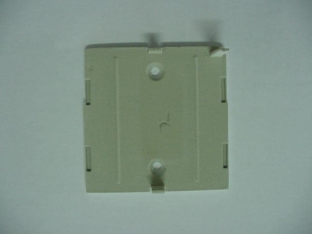
RUF150704
Feb 11, 2004Door/Window Sensor
Equipment Class
DSS - Part 15 Spread Spectrum Transmitter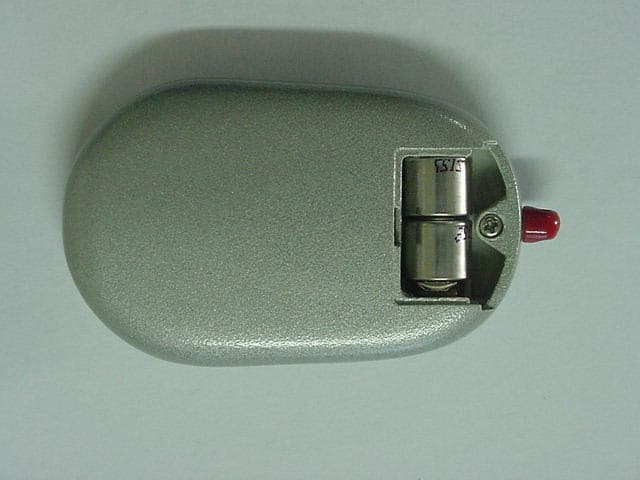
RUF150702
Feb 11, 20045-Function Key Fob
Equipment Class
DSS - Part 15 Spread Spectrum Transmitter