RUF150706IntegrAlarm Remote Siren/Strobe
EMTS Inc.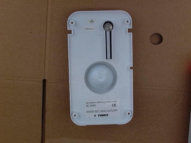
Click to zoom
Application Details
- Equipment Class
- DSS - Part 15 Spread Spectrum Transmitter
- Date of Grant
- Jun 22, 2004
- Application Purpose
- Original Equipment
- Date of Application
- Jun 22, 2004
- Equipment Note
- IntegrAlarm Remote Siren/Strobe
- Frequency Range
- 903.50000000 - 913.50000000
- Company
- EMTS Inc.
- Country
- Canada
Documents & Files
Document Text
Text extracted from the exhibit documents filed with the FCC. Open a document above to read the original.
Users Manual
Page 1 of 12 Document # E.0015.16.07 443713.DOC IntegrAlarm USER AND INSTALLER MANUAL (REMOTE SIREN / STROBE UNIT) IntegrAlarm MODEL IA-SRN1 May 16, 2004 Page 2 of 12 Document # E.0015.16.07 443713.DOC Table of Contents 1 IntegrAlarm Overview..................................................................................... 3 2 Remote Siren/Strobe Unit.............................................................................. 5 2.1 Description....................................................................................................... 5 2.2 Technical Specifications................................................................................. 6 3 Installation........................................................................................................ 7 4 Enrolling Procedure........................................................................................ 8 4.1 General............................................................................................................. 8 4.2 Siren / Strobe Unit Enrollment....................................................................... 8 5 Place Test....................................................................................................... 11 Page 3 of 12 Document # E.0015.16.07 443713.DOC 1 IntegrAlarm Overview The IntegrAlarm wireless security system includes a Control Panel and a number of wireless peripheral units. The system operates on the ISM wireless band of 902-928 MHz, in frequency hopping mode, transmitting short (about 10 ms) packets of data, with each packet transmitted on a different frequency. The system operates on 56 pseudo random selected channels. Time and frequency synchronization is maintained by a synchronization signal transmitted by the system Control Panel to the various peripherals (including the IA SRN-1) every 3 minutes. The IntegrAlarm system is a two-way communication system; every data or command packet is validated using a high level of error detection code (CRC) and acknowledged back to the transmitting source. Automatic repeat request (ARQ) is provided in case of unacknowledged data or command packet. In its present configuration, the system includes five types of peripheral units: • Door / window magnetic sensor. • PIR motion detector. • Smoke detector. • 5-function key fob (handheld remote control). • Remote siren / strobe. This manual is devoted to the installation instructions for the IntegrAlarm IA SRN-1 siren/strobe unit. The installation instructions for the other IntegrAlarm peripherals and the IntegrAlarm Control Panel appear in the User and Installer Manuals for the respective units. Page 4 of 12 Document # E.0015.16.07 443713.DOC FCC Compliance Statement The FCC Wants You to Know This equipment has been tested and found to comply with the limits for a Class B digital unit, pursuant to Part 15 of the FCC rules. These limits are designed to provide reasonable protection against harmful interference in a residential installation. This equipment generates, uses and can radiate radio frequency energy and, if not installed and used in accordance with the instructions, may cause harmful interference to radio communications. However, there is no guarantee that interference will not occur in a particular installation. If this equipment does cause harmful interference to radio or television reception, which can be determined by turning the equipment off and on, the user is encouraged to try to correct the interference by one or more of the following measures: a) Reorient or relocate the receiving antenna. b) Increase the separation between the equipment and receiver. c) Connect the equipment to an outlet on a circuit different from that to which the receiver is connected. d) Consult the dealer or an experienced radio technician. FCC ID: RUF150706, Canadian Industry IC: 4937A-150706 This unit complies with Part 15 of the FCC Rules. Operation is subject to the following two conditions: (1) This unit may not cause harmful interference and (2) This unit must accept any interference received, including interference that may cause undesired operation. FCC Warning Modifications not expressly approved by the manufacturer could void the user authority to operate the equipment under FCC Rules. Instructions concerning human exposure to radio frequency electromagnetic fields. To comply with FCC Section 1.307 (b)(1) for human exposure to radio frequency electromagnetic fields, implement the following instruction: A distance of at least 20cm. between the equipment and all persons should be maintained during the operation of the equipment. Page 5 of 12 Document # E.0015.16.07 443713.DOC 2 Remote Siren/Strobe Unit 2.1 Description The IntegrAlarm model IA-SRN1 remote siren / strobe unit consists of an RF transceiver, a micro-controller with non-volatile memory, siren generator and amplifier, a piezo element and horn, a high voltage power supply and a discharge tube, a power supply with back-up batteries, and a wall mounted mains isolation transformer, 115 to 12 VAC. The remote siren / strobe unit is composed of the following principal parts: • Top cover in two sections: opaque white and transparent red. • Siren / strobe unit base with siren piezo element and horn, battery holder for 6 NiCad rechargeable batteries and two tamper switch actuators. • RF / controller, siren and strobe circuitry PCB with strobe discharge tube. • 6 AA NiCad rechargeable batteries (7.2 V). • Wall mounted mains isolation transformer, 115 to 12 VAC. An exploded view of the IA-SRN1 remote siren / strobe unit is shown in Figure 1 below. The IA-SRN1 remote siren receiver continuously monitors the control panel synchronization and command packets. Upon receiving a command packet that contains the correct system and peripheral ID, the IA-SRN1 remote siren controller will acknowledge the receive packet and activate the siren in the requested pattern with or without the strobe. In case of tamper, the IA-SRN1 sen…
Text truncated - open the document above for the full version.
Cover Letter(s)
EMTS INC. 300 Alden Road Markham, Ontario L3R 4C1 Canada Date: February 25, 2004 To: MET Laboratories Inc. To Whom it may Concern, We hereby authorize I.T.L. (Product Testing) Ltd. (ITL) to act on our behalf regarding the FCC ID Certification process for the following applications: IA-FOB1FCC ID: RUF150702 IA-PIR1FCC ID: RUF150703 IA-DWC1FCC ID: RUF150704 IA-CP1FCC ID: RUF150701 IA-SMK1FCC ID: RUF150705 IA-SNR1FCC ID: RUF150706 Thank you, Signature............... Doron Lavee Engineering Manager
Cover Letter(s)
EMTS INC. 300 Alden Road Markham, Ontario L3R 4C1 Canada May 01, 2004 Reviewing Engineer Federal Communications Commission 7435 Oakland Mills Road Columbia, MD 21046 USA RE:Confidentiality request for the following unit: IntegrAlarm IA-SRN1 Remote Siren / Strobe FCC ID RUF150706 To Whom It May Concern: This letter serves as an official request for confidentiality under FCC Rule Section 0.459. We have requested that the block diagram, schematics and technical description of the above captioned unit, which are required to be submitted with this application be withheld from public review due to patent pending on the above item. Please contact me if there is any information you may need. Sincerely, Doron Lavee Engineering Manager EMTS Inc. Date: January 7, 2004 Tel. (905) 946-8477 Fax (905) 947-0138
External Photos
External Photos of Tested E.U.T. Figure 1 Front View Figure 2 Rear View
ID Label/Location Info
8. FCC Label FCC ID: RUF150706 This device complies with Part 15 of the FCC Rules. Operation is subject to the following two conditions: (1) This device may not cause harmful interference and (2) This device must accept any interference received, including interference that may cause undesired operation. IA-SRN1 Remote siren Labels Size and location 130 mm 230 mm FCC label Product label FCC ID: RUF150706IC: 4937A-150706 This device complies with Part 15 of the FCC rules. Operation is subject to the following two conditions: (1)This device may not cause harmful interference and (2) This device must accept any interference received, including interference that may cause undesired operation 20 mm 50 mm FCC label 30 mm 20 mm IntegrAlarm Remote siren Model IA-SRN1 S/N xxxxxxxx Product label Labels location: on product back cover Horn
Internal Photos
Internal Photographs of Tested E.U.T. Figure 1 Front Cover Internal View Figure 2 Unit Without Cover Figure 3 PCB in Unit Figure 4 PCB Side 1 Without Shield Figure 5 PCB Side 2
Test Report
Cert. No. 1152.01 Electrical (EMC) Test Report E522311.00 EMTS Inc. Page 1 of 73 FCC ACC M Ver 1.1 05Mayl 2000 DATE: 27 May 2004 I.T.L. (PRODUCT TESTING) LTD. EMC Test for EMTS Inc. Equipment under test: IntegrAlarm Remote Siren/Strobe Unit (Transmitter Section) IA-SRN1 Written by: _____________________________ D. Shidlowsky, Documentation Approved by: _____________________________ E. Pitt, Test Engineer Approved by: _____________________________ I. Raz, EMC Laboratory Manager This report must not be reproduced, except in full, without the written permission of I.T.L. (Product Testing) Ltd. This report relates only to items tested. Cert. No. 1152.01 Electrical (EMC) Test Report E522311.00 EMTS Inc. Page 2 of 73 FCC ACC M Ver 1.1 05Mayl 2000 Measurement/Technical Report for EMTS Inc. IntegrAlarm Remote Siren/Strobe Unit (For Transmitter Section) IA-SRN1 FCC ID:RUF150706 27 May 2004 This report concerns: Original Grant x Class II change Class B verification Class A verification Class I change Equipment type: Radio Telemetry Transmitter Request Issue of Grant: x Immediately upon completion of review Limits used: CISPR 22 Part 15 x Measurement procedure used is ANSI C63.4-2001. Application for Certification Applicant for this device: prepared by: (different from "prepared by") Ishaishou Raz Doron Lavee ITL (Product Testing) Ltd. EMTS Inc. Kfar Bin Nun 300 Alden Road D.N. Shimshon 99780 Markham, Ontario, L3R4C1 Israel Canada e-mail [email protected] Tel: +1-905-946-8589 Fax: +1-905-947-0138 e-mail: [email protected] Test Report E522311.00 EMTS Inc. Page 3 of 73 FCC ACC M Ver 1.1 05Mayl 2000 TABLE OF CONTENTS 1. GENERAL INFORMATION ------------------------------------------------------------------------------- 5 1.1 Administrative Information.................................................................................5 1.2 List of Accreditations .........................................................................................6 1.3 Product Description ...........................................................................................7 1.4 Test Methodology..............................................................................................8 1.5 Test Facility .......................................................................................................9 1.6 Measurement Uncertainty .................................................................................9 2. PRODUCT LABELING -----------------------------------------------------------------------------------10 3. SYSTEM TEST CONFIGURATION--------------------------------------------------------------------12 3.1 Justification......................................................................................................12 3.2 EUT Exercise Software ...................................................................................12 3.3 Special Accessories ........................................................................................12 3.4 Equipment Modifications .................................................................................12 3.5 Configuration of Tested System ......................................................................13 4. BLOCK DIAGRAM-----------------------------------------------------------------------------------------13 4.1 Schematic Block/Connection Diagram............................................................13 4.2 Theory of Operation ........................................................................................13 5. CUSTOMER’S DECLARATION ------------------------------------------------------------------------14 6. CONDUCTED AND RADIATED MEASUREMENT PHOTOS ----------------------------------15 7. CONDUCTED EMISSION DATA-----------------------------------------------------------------------16 7.1 Test Specification ............................................................................................16 7.2 Test Procedure................................................................................................16 7.3 Measured Data................................................................................................17 7.4 Test Instrumentation Used, Conducted Measurement ...................................20 8. SPURIOUS RADIATED EMISSION, BELOW 1 GHZ---------------------------------------------21 8.1 Test Specification ............................................................................................21 8.2 Test Procedure................................................................................................21 8.3 Measured Data................................................................................................21 8.4 Test Instrumentation Used, Radiated Measurements ....................................22 8.5 Field Strength Calculation ...............................................................................23 9. SPURIOUS RADIATED EMISSION ABOVE 1 GHZ ----------------------------------------------24 9.1 Radiated Emission Above 1 GHz....................................................................24 9.2 Test Data .........................................................................................................24 9.3 Test Instrumentation Used, Radiated Measurements Above 1 GHz ..............33 10. MAXIMUM TRANSMITTED PEAK POWER OUTPUT -------------------------------------------34 10.1 Test procedure ................................................................................................34 10.2 Results table....................................................................................................35 10.3 Test Equipment Used......................................................................................36 11. PEAK POWER OUTPUT OUT OF 902-928 MHZ BAND ----------------------------------------37 11.1 Test procedure ................................................................................................37 11.2 Results table...................................…
Text truncated - open the document above for the full version.
Test Setup Photos
Tests Setup Photos Figure 1. Conducted Emission Test. Figure 2. Radiated Emission Test.
Contact Information
Applicant
Joel Kligman
Test Firm
ITL Product Testing LTDSteli Loznen
Technical Specifications
| # | Rule Parts | Frequency Range | Power Output |
|---|---|---|---|
| 1 | 15C | 903.5 MHz - 913.5 MHz | 20.00 mW |
Other Applications from EMTS Inc.
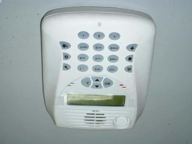
RUF150701
Mar 20, 2004IntegrAlarm Control Panel
Equipment Class
DSS - Part 15 Spread Spectrum Transmitter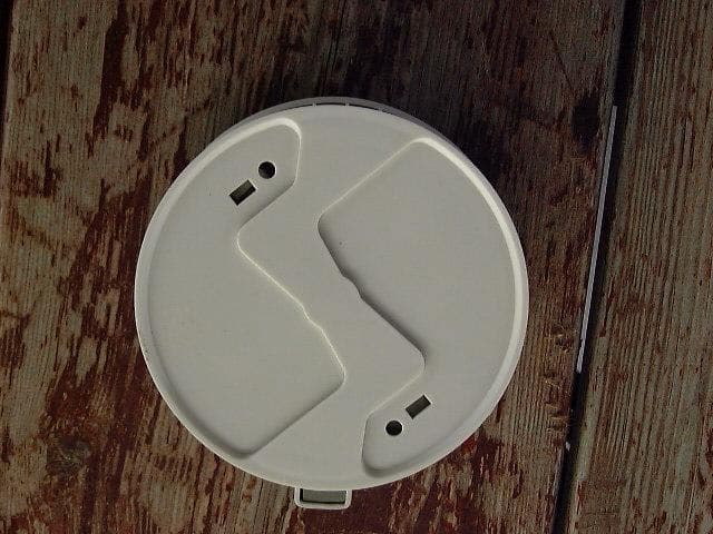
RUF150705
Feb 29, 2004Integr Alarm Wireless Smoke Detector
Equipment Class
DSS - Part 15 Spread Spectrum Transmitter
RUF150704
Feb 11, 2004Door/Window Sensor
Equipment Class
DSS - Part 15 Spread Spectrum Transmitter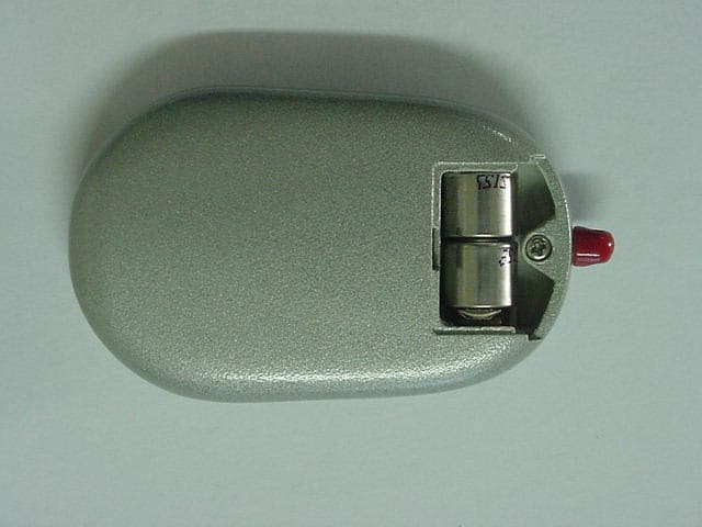
RUF150702
Feb 11, 20045-Function Key Fob
Equipment Class
DSS - Part 15 Spread Spectrum Transmitter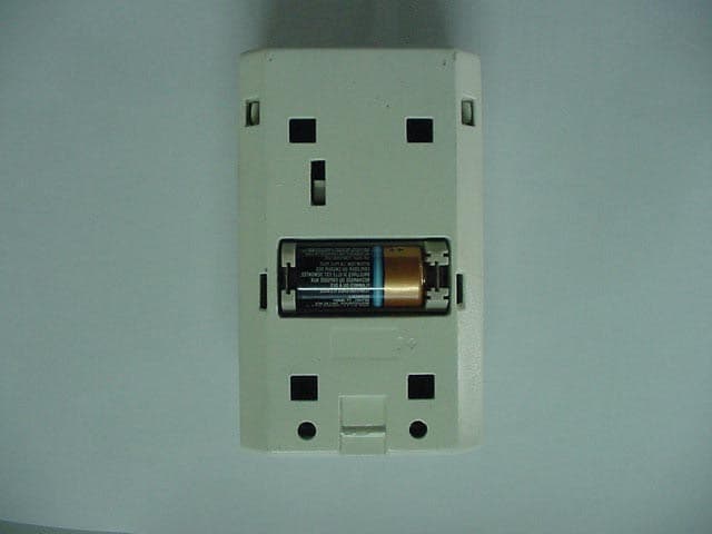
RUF150703
Feb 11, 2004Passive Infra Red Motion Detector
Equipment Class
DSS - Part 15 Spread Spectrum Transmitter