RWB-MT9100RESROC RMS Repeater
MetroTel Corp of Minnesota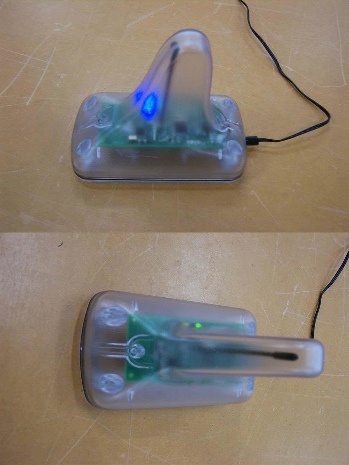
Click to zoom
Application Details
- Equipment Class
- DTS - Digital Transmission System
- Date of Grant
- Aug 30, 2006
- Application Purpose
- Original Equipment
- Date of Application
- Aug 27, 2006
- Equipment Note
- ESROC RMS Repeater
- Frequency Range
- 916.48000000 - 916.48000000
- Company
- MetroTel Corp of Minnesota
- Country
- United States
Documents & Files
Document Text
Text extracted from the exhibit documents filed with the FCC. Open a document above to read the original.
Users Manual
WESROC ® Repeater ~ WESROC ® Repeater MT-9100R – AC MT-9100R – ACO The Wesroc ® RMS Repeater is used for extending the effective range of the transmissions of any Wesroc ® remote telemetry system. Simply place the repeater in a location that is as close as equally distant from the transmitter and the base unit as possible. The AC version has an AC power adapter permanently attached and is for indoor use only. The ACO (AC powered, Outdoor) version of the repeater is weatherproof and is suitable for any outdoor location. The repeater comes with either a permanently connected power supply (AC version) or a 25 foot cord and an external power supply (ACO version). To put the repeater into operation, simply plug it in. The ACO version of the repeater can be outdoors, but the plug-in power supply must be indoors or sufficiently out of the elements. The ACO version of the repeater and its power supply have mating coaxial DC power connectors. This is so a hole can be drilled in an outside wall and the connection to the power adapter made inside. Any number of repeaters can be "daisy chained" to extend the effective range even further. The repeater functions differently when it must cooperate with other repeaters. No configuration is necessary as this function is automatic. WARRANTY INFORMATION Independent Technologies, Inc. (ITC) warrants the MT- 9100R WESROC ® RMS Repeater against defects in materials or workmanship for a period of one year from date of shipment to original purchaser. All units deemed defective under this warranty will be replaced or repaired at ITC’s option. No other warranty is expressed or implied, nor will responsibility for operation of this device be assumed by ITC. Radio Frequency Exposure Warning To ensure that exposure to hazardous radio frequency radiation is prevented, this equipment must not be installed in a location where humans will be routinely within 20 centimeters of it. To ensure that FCC requirements are met regarding radio frequency exposure, Wesroc RMS Repeaters are not to be placed in operation where they will be collocated with other Wesroc RMS Repeaters. Collocation is considered to be where one operating Wesroc RMS Repeater is within 20 centimeters of another operating Wesroc RMS Repeater. Radio Interference This equipment (FCC ID number RWB-MT9100R and IC number 115A-MT9100R) has been tested and found to comply with the limits for a Class B digital device, pursuant to part 15 of the FCC Rules. These limits are designed to provide reasonable protection against harmful interference in a residential installation. This equipment generates, uses, and can radiate radio frequency energy and, if not installed and used in accordance with the instructions may cause harmful interference to radio communications. However, there is no guarantee that interference will not occur in a particular installation. If this equipment does cause harmful interference to radio or television reception, which can be determined by turning the equipment off and on, the user is encouraged to try to correct the interference by one or more of the following measures: • Reorient or relocate the receiving antenna. • Increase the separation between the equipment and receiver. • Connect the equipment into an outlet on a circuit different from that to which the receiver is connected. • Consult the dealer or an experienced radio/TV technician for help. The Wesroc RMS Repeater contains no user serviceable parts. Any changes or modifications to the Wesroc RMS Repeater that are not expressly approved by Independent Technologies could void authorization to use the Wesroc RMS repeater. Copyright © 2006 - Independent Technologies, Inc. - Ph: 402-496-4700 Do not reproduce without permission.
External Photos
Current Enclosure Screwed together and sealed via a gasket. New Enclosure Utilizes the same pcb but is sealed via ultrasonic welding.
ID Label/Location Info
IC: 115A-MT9100RFCC ID: RWB-MT9100R METROTEL CORP OMAHA, NE 402-498-2964 www.MetroTelCorp.com B A REMOVED LED INSTRUCTIONS03-07-06 B ADDED FCC INFORMATION04-24-06 (SCALE 2:1) DETAIL 'A' SEE DETAIL 'A' FCC ID: RWB-MT9100RIC: 115A-MT9100R
RF Exposure Info
NCEE Labs R030906-03 FCC ID: RWB-MT9100R IC: 115A-MT9100R Page 37 of 39 FCC ID: RWB-MT9100R RF Exposure Statement for MT9100R: Notice in Installation Manual: FCC Radiation Exposure Statement This equipment complies with FCC radiation exposure limits set forth for an uncontrolled environment. This equipment should be installed and operated with minimum distance 1.88cm (0.75 inches) between the radiator and your body. RF Exposure Calculations: The following information provides the minimum separation distances for the two major antenna types used in this system. Directional Antenna: The 8dBi antenna is the maximum gain antenna certified for use with the product. The minimum separation distance is calculated from FCC OET 65 Appendix B, Table 1B Guidelines for General Population/Uncontrolled Exposure. This calculation is based on the highest EIRP possible from the system, considering maximum power and antenna gain. The exposure limit for a transmitter operating at 905.5MHz is found in mW/cm^2 using the equations f/1200. Since the operating frequency in channel DA produced the lowest limit, that limit will be used in calculation. (905.5/1200 = 0.75mW/cm^2) S = (Po * G) / (4 * Pi * r^2) or r = SQRT [ (Po * G) / (4 * Pi * S) ] Where S = 0.75 mW/cm^2 for 915 MHz Where Po = 5.38 mW (Peak RF, 7.31dBm) Where G = 6.31 (numeric equivalent to 8dBi antenna gain with 0.0 dB cable loss) Where r = Minimum Safe Distance from antenna (cm) For Po = 5.38mW, r = 1.88cm ( 0.75 inches) For a distance [r] of 20cm from this antenna, the field density S = 0.0068 mW/cm^2 Notes: 1. The minimum safe distance is based on a conservative “worst case” prediction, i.e. using the formula shown above and no duty factor. In practice the minimum distance will be much shorter. (Ref. 2) 2. The minimum safe distance has been calculated for the maximum allowed Power Density (S) limit of 0.75 mW/cm^2 for the frequency 915 MHz for uncontrolled environments (Ref. 2). References: 1. FCC Part 15, sub-clause 15.247 (b) (4) (i) 2. FCC OET Bulletin 65, Edition 97-01 3. FCC Supplement C to OET Bulletin 65, edition 01-01
Test Report
Test Report with Amendment (R030906-03) Company: MetroTel Corp 26 First Ave SE New London, MN 56273 Contact: Doug Ferguson Product: MT-9100R-AC, MT-9100R-ACO Wesroc RMS Repeater FCC ID: RWB-MT9100R IC: 115A-MT9100R Test Report No: R030906-03B APPROVED BY: Doug Kramer _________________________ Senior Test Engineer DATE: 29 August 2006 Total Pages: 39 The Nebraska Center for Excellence in Electronics (NCEE) authorizes the above named company to reproduce this report provided it is reproduced in its entirety for use by the company’s employees only. Any use that a third party makes of this report, or any reliance on or decisions made based on it, are the responsibility of such third parties. NCEE accepts no responsibility for damages, if any, suffered by any third party as a result of decisions made or actions based on this report. This report applies only to the items tested. NCEE is a FCC and Industry Canada registered lab. FCC #100875, IC #4294 NCEE Labs R030906-03B FCC ID: RWB-MT9100R IC: 115A-MT9100R Page 2 of 39 1.0 Summary of test results 1.1 Test Results 1.2 Test Methods 1.2.1 Conducted Emissions 1.2.2 Radiated Emissions 2.0 Description 2.1 Equipment under test 2.2 Laboratory description 2.3 Description of test modes 2.4 Applied standards 2.5 Description of support units 2.6 Configuration of system under test 3.0 Test equipment used 4.0 Detailed Results 4.1 Unique antenna requirement 4.2 Radiated Emissions 4.3 Conducted AC Mains Emissions 4.4 Bandwidth 4.5 Maximum peak output power 4.6 Power spectral density (PSD) 4.7 Bandedges Appendix A – Test photos Appendix B – Sample calculation Appendix C – RF exposure evaluation Appendix D – Table of figures NCEE Labs R030906-03B FCC ID: RWB-MT9100R IC: 115A-MT9100R Page 3 of 39 1.0 Summary of test results 1.1 Test Results The EUT has been tested according to the following specifications: APPLIED STANDARDS: FCC Part 15, Subpart C Standard Section Test Type and Limit Result Remark 15.203 RSS-Gen Unique Antenna Requirement Pass PCB Antenna 15.207 RSS-Gen Conducted Emissions Pass Meets the requirement of the limit. 15.209 RSS-Gen Radiated Emissions Pass Meets the requirement of the limit. 15.247(a)(2) RSS-210 Issue 6 Minimum Bandwidth, Limit: Min. 500kHz Pass Meets the requirement of the limit. 15.247(b) RSS-210 Issue 6 Maximum Peak Output Power, Limit: Max. 30dBm Pass Meets the requirement of the limit. 15.247(c) RSS-210 Issue 6 Transmitter Radiated Emissions, Limit: Table 15.209 Pass Meets the requirement of the limit. 15.247(d) RSS-210 Issue 6 Power Spectral Density, Limit: Max. 8dBm Pass Meets the requirement of the limit. 15.247(c) RSS-210 Issue 6 Band Edge Measurement, Limit: 20dB less than the peak value of fundamental frequency Pass Meets the requirement of the limit. NCEE Labs R030906-03B FCC ID: RWB-MT9100R IC: 115A-MT9100R Page 4 of 39 1.2 Test Methods 1.2.1 Conducted Emissions The EUT was powered by an AC adapter that converted 120VAC/60Hz to 9VDC. Conducted emissions measurements were made according to ANSI/IEEE C63.4: 2003 and compared to the limits as found in 47 CFR Part 15.207. Both models MT-9100R-AC and MT-9100R-ACO were tested, the difference being the length of the power supply cable. 1.2.2 Radiated Emissions Compliance to 47 CFR Parts 15.209 and 15.247 was tested in accordance with the methods of ANSI/IEEE C63.4: 2003. Several configurations were examined and the results presented represent a worst-case scenario. The EUT was placed on a wooden table approximately 80cm high and centered on a 4m diameter turntable. The table was rotated to find the angles of maximum emissions and the receiving antenna was moved from 1m to 4m in both vertical and horizontal positions. The EUT was tested while sitting both vertically and horizontally. The horizontal configuration produced the highest emissions, and that position was used for all radiated testing. All measurements were taken at a distance of 3m from the EUT for Part 15.209 intentional radiator measurements, and 3m for 15.247 measurements of the fundamental frequency in the 902MHz to 928MHz band and subsequent harmonics. 1.3 Reason for amendment This test report has been amended to correct details on the output power of the transmitter as shown on page 5 and details regarding measurements above 1GHz. NCEE Labs R030906-03B FCC ID: RWB-MT9100R IC: 115A-MT9100R Page 5 of 39 2.0 Description 2.1 Equipment under test The Equipment Under Test (EUT) was a Wesroc RMS repeater (MT9100R), which is designed to communicate directly with any WESROC remote telemetry system. Any number of repeaters can be “daisy-chained” together to extend the effective range further. All functions are automatic and no user configuration is required. The EUT is only capable of transmitting at 916.48MHz. This frequency will be referred to as Channel 1. EUT Received Date: 25 July 2006 EUT Tested Date: 25 July 2006 PRODUCT Wesroc RMS Repeater MODEL MT-9100R-AC, MT-9100R-ACO POWER SUPPLY AC adapter, 9VDC MODULATION TYPE QFSK RADIO TECHNOLOGY Half-duplex RF Link TRANSFER RATE 2400 bit per second, transmit and receive FREQUENCY RANGE 916.48 MHz NUMBER OF CHANNELS 1 MAXIMUM OUTPUT POWER 5.38mW; 7.3dBm ANTENNA TYPE Internal, PCB mounted DATA CABLE N/A I/O PORTS N/A ASSOCIATED DEVICES N/A NOTE: 1. For more detailed features description, please refer to the manufacturer's specifications or User's Manual. 2.2 Laboratory description All testing was performed at the NCEE Lincoln facility, which is a FCC and IC registered lab. This site has been fully described in previously submitted reports. Laboratory environmental conditions varied slightly throughout the tests: Relative humidity of 45 ± 4% Temperature of 20 ± 3° Celsius NCEE Labs R030906-03B FCC ID: RWB-MT9100R IC: 115A-MT9100R Page 6 of 39 2.3 Description of test modes Channel Frequency 1 916.48 MHz 2.4 Applied standards The EUT is a digital transmission device operating between 902 MHz and 928 MHz. According to the specifications of the manufacturer, it must comply with…
Text truncated - open the document above for the full version.
Test Setup Photos
NCEE Labs R030906-03 FCC ID: RWB-MT9100R IC: 115A-MT9100R Page 29 of 39 Appendix A: Test Photos NCEE Labs R030906-03 FCC ID: RWB-MT9100R IC: 115A-MT9100R Page 30 of 39 Figure 12 - MT9100R Figure 13 - Conducted Emissions Test Setup, MT-9100R-ACO NCEE Labs R030906-03 FCC ID: RWB-MT9100R IC: 115A-MT9100R Page 31 of 39 Figure 14 - Conducted Emissions Test Setup Figure 15 - Conducted Emissions Test Setup, MT-9100R-AC NCEE Labs R030906-03 FCC ID: RWB-MT9100R IC: 115A-MT9100R Page 32 of 39 Figure 16 - Radiated Emissions Test Setup Figure 17 - Radiated Emissions Test Setup NCEE Labs R030906-03 FCC ID: RWB-MT9100R IC: 115A-MT9100R Page 33 of 39 Figure 18 - Radiated Emissions Test Setup
Contact Information
Applicant
Kripa Sharma
Technical Contact
MetroTel Corporation of MinnesotaDoug Ferguson
[email protected]320 354 2929
26 First Aenue S.E. · New London, Minnesota · United States
Non-Technical Contact
MetroTel Corporation of MinnesotaDoug Ferguson
[email protected]320 354 2929
Test Firm
Nebraska Center for Excellence in ElectronicsNic Johnson
Technical Specifications
| # | Rule Parts | Frequency Range | Power Output |
|---|---|---|---|
| 1 | 15C | 916.48 MHz - 916.48 MHz | 5.40 mW |
Other Applications from MetroTel Corp of Minnesota
RWBMT9103CBU
Dec 30, 2014Cellular Tank Monitor
Equipment Class
DTS - Digital Transmission System
RWBMT9100CTM
Jun 23, 2011Tank Monitoring System
Equipment Class
DTS - Digital Transmission System
RWBMT9100TNK
Oct 17, 2007Fuel Tank Level Transmitter
Equipment Class
DTS - Digital Transmission System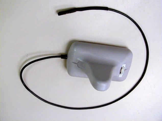
RWB-MT9100T
Mar 28, 2004WESROC RMS Transmitter MT-9100T
Equipment Class
DXX - Part 15 Low Power Communication Device Transmitter