RWB-MT9100TWESROC RMS Transmitter MT-9100T
MetroTel Corp of Minnesota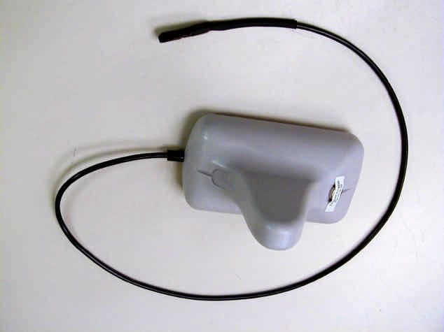
Click to zoom
Application Details
- Equipment Class
- DXX - Part 15 Low Power Communication Device Transmitter
- Date of Grant
- Mar 28, 2004
- Application Purpose
- Original Equipment
- Date of Application
- Mar 28, 2004
- Equipment Note
- WESROC RMS Transmitter MT-9100T
- Frequency Range
- 916.48000000 - 916.48000000
- Company
- MetroTel Corp of Minnesota
- Country
- United States
Documents & Files
Document Text
Text extracted from the exhibit documents filed with the FCC. Open a document above to read the original.
Users Manual
Rev. A 02/26/2004 WESROC RMS Transmitter Data Sheet for models MT-9100T, MT-9100T-XC and MT-9100T-LD Functionality The WESROC RMS Transmitter is used to measure the level inside of a liquid propane tank. The tank level and additional status information are sent via a wireless link to a WESROC RMS Base Unit. The Transmitter is designed to be installed on the outside of a liquid propane tank and be connected to a sensor ready dial on a liquid level tank gauge. Please refer to the WESROC RMS Base Unit and Transmitter Installation Guide for detailed installation instructions. WARNING: DO NOT REMOVE THE SCREWS HOLDING THE TANK GAUGE HEAD IN PLACE!!! TANK DECOMPRESSION CAN CAUSE SERIOUS INJURY AND/OR PROPERTY DAMAGE!!! The Transmitter has four basic operating modes. The following table defines the operating modes and programming magnet positions for each of the modes. NOTE: To maximize battery life, Transmitters should set to the STOP mode when not in use. Operating Mode OFF Position INIT Position STOP X INITIALIZATION X TANK NUMBER X X NORMAL Service The WESROC RMS Transmitter does not contain any field serviceable components. The Transmitter’s internal batteries are not field replaceable. If a Transmitter is not functioning properly, it should be returned to the factory for service or replacement. Radio Interference This equipment has been tested and found to comply with the limits for a Class B digital device, pursuant to part 15 of the FCC Rules. These limits are designed to provide reasonable protection against harmful interference in a residential installation. This equipment generates, uses, and can radiate radio frequency energy and, if not installed and used in accordance with the instructions may cause harmful interference to radio communications. However, there is no guarantee that interference will not occur in a particular installation. If this equipment does cause harmful interference to radio or television reception, which can be determined by turning the equipment off and on, the user is encouraged to try to correct the interference by one or more of the following measures: • Reorient or relocate the receiving antenna. • Increase the separation between the equipment and receiver. • Connect the equipment into an outlet on a circuit different from that to which the receiver is connected. • Consult the dealer or an experienced radio/TV technician for help. Safety The WESROC RMS Transmitter has been certified as an Intrinsically Safe Apparatus for use in Class I, Division 1, Group D Hazardous (Classified) Locations per ANSI/UL 913 and CAN/CSA C22.2 No. 157. Metrotel Corporation An Independent Technologies Company Omaha, NE 402-498-2964 www.MetroTelCorp.com
ID Label/Location Info
THIS DEVICE COMPLIES WITH PART 15 OF THE FCC RULES. OPERATION IS SUBJECT TO THE FOLLOWING CONDITIONS: THIS DEVICE MAY NOT CAUSE HARMFUL INTERFERENCE AND THIS DEVICE MUST ACCEPT ANY INTERFERENCE RECEIVED INCLUDING INTERFERENCE THAT MAY CAUSE UNDESIRED OPERATION. INTRINSICALLY SAFE APPARATUS FOR USE IN CLASS I,DIVISION 1,GROUP D HAZARDOUS (CLASSIFIED) LOCATIONS PER ANSI/UL 913 AND CAN/CSA C22.2 NO. 157 ETL: XXXXXXX CUS MODEL PATENTS PENDING METROTEL CORP OMAHA, NE 402-498-2964 www.MetroTelCorp.com MT-9100T FCC ID: RWB-MT9100TIC:115A-MT9100T 98-06-171A 1:1 REV DWG NO. FSCM NO. SIZE SCALE SHEET APPROVEDDATEDESCRIPTIONREV REVISIONS METROTEL CORP. 1 OF 1 A ARTWORK PRINT DETAIL WARMS TRANSMITTER BOTTOM PRODUCTION RELEASEA02-25-04 (SCALE 2:1) DETAIL 'A' 1. PRINT TO BE SILKSCREENED USING BLACK INK NOTES: SEE DETAIL 'A' FCC ID: RWB-MT9100TIC:115A-MT9100T
Test Report
MetroTel Corporation of Minnesota Application For Certification MT-9100T Transmitter FCC ID: RWB-MT9100T February, 2004 Intertek ETL SEMKO 7250 Hudson Boulevard, Suite 100, Oakdale, MN 51228 Telephone 651-730-1188, Fax 651-730-1282 Home Page www.intertek.com CONTENTS 1.0 GENERAL DESCRIPTION............................................................................ 1 1.1 Related Submittals Grants ................................................................................... 1 1.2 Product Description........................................................................................... 1 1.3 Test Methodology............................................................................................. 1 1.4 Test Facility.................................................................................................... 1 2.0 SYSTEM TEST CONFIGURATION................................................................ 2 2.1 Justification .................................................................................................... 2 2.2 EUT Exercising Software ................................................................................... 2 2.3 Special Accessories ........................................................................................... 2 2.4 Equipment Modification ..................................................................................... 2 2.5 Support Equipment List and Description.................................................................. 2 2.6 Test Configuration Block Diagrams ....................................................................... 3 3.0 TEST RESULTS........................................................................................... 4 3.1 Field Strength of Fundamental and Harmonics Emissions, FCC 15.249(a)(b), 15.205 ........... 5 3.2 Out of Band Spurious Emissions, FCC 15.249(c), 15.209 ............................................ 9 3.3 RSS 210 6.2.2(m2) Occupied Bandwidth ................................................................ 11 3.4 Test Procedure................................................................................................ 13 3.5 Field Strength Calculation .................................................................................. 14 4.0 TEST EQUIPMENT.....................................................................................15 FCC ID: RWB-MT9100T February 2004 Page 1 of 15 1.0 GENERAL DESCRIPTION 1.1 Related Submittals Grants This is single application of the MetroTel MT-9100T Transmitter for Certification under FCC Part 15, Subpart C. There are no other simultaneous applications. The Receiver portion will be verified under Declaration of Conformity. 1.2 Product Description MT-9100T Transmitter operates at 916.48MHz. The MT-9100T Transmitter intended to be installed with propane gas tank and using the device sensor checks the gas level. The intended use of the MT- 9100T Transmitter is to generate and transmit a RF signal to control Base Unit (Receiver). The MT- 9100T Transmitter powered from two 3.6V internal lithium batteries. Antenna Description: Non-detachable from the PCB ¼ wavelength monopole antenna. Sample Submitted: February 19, 2004 Test Work Started: February 19, 2004 Test Work Completed: February 20, 2004 1.3 Test Methodology Emission measurements were performed according to the procedures in ANSI C63.4-2000. All field strength radiated emissions measurements were performed in the semi-anechoic chamber, and for each scan, the procedure for maximizing emissions in Appendices D and E were followed. All field strength radiated tests were performed at an antenna to EUT distance of 3 meters, unless stated otherwise in the "Justification Section" of this Application. 1.4 Test Facility The test site facility used to collect the radiated and conducted measurement data is located at 7250 Hudson Blvd., Suite 100, Oakdale, Minnesota. This test facility has been fully described in a report dated on March 2003 submitted to FCC. Please reference the site registration number: 90706, dated April 18, 2003. FCC ID: RWB-MT9100T February 2004 Page 2 of 15 2.0 SYSTEM TEST CONFIGURATION 2.1 Justification For simplicity of testing, the transmitter was wired to transmit continuously. 2.2 EUT Exercising Software N/A 2.3 Special Accessories There are no special accessories necessary for compliance of these products. 2.4 Equipment Modification No modifications were installed during the testing. 2.5 Support Equipment List and Description N/A FCC ID: RWB-MT9100T February 2004 Page 3 of 15 2.6 Test Configuration Block Diagrams The EUT was setup as tabletop equipment. The EUT was powered from two 3.6V internal lithium batteries. Field Strength Measurements FCC ID: RWB-MT9100T February 2004 Page 4 of 15 3.0 TEST RESULTS Data is included for the worst case configuration (the configuration which resulted in the highest emission levels). A sample calculation, configuration photographs, data tables and graphical representations of the emissions are included. The EUT is intended for operation under the requirements of Part 15 Subpart C. Specific test requirements include the following: 47 CFR 15.249(a)(b) Field Strength of Fundamental 47 CFR 15.249(a)(b), 15.205 Field Strength of Harmonics 47 CFR 15.249(c), 15.209 Out of Band Spurious Emissions RSS 210 6.2.2(m2) Occupied Bandwidth Note: A Conducted emissions testing was not performed as battery powered equipment. FCC ID: RWB-MT9100T February 2004 Page 5 of 15 3.1 Field Strength of Fundamental and Harmonics Emissions, FCC 15.249(a)(b), 15.205 Field Strength of Fundamental and Harmonics Emissions measurements were made with Fundamental frequency at 916.48MHz. The Harmonics emissions were tested up to 10 th harmonic. The EUT complies with the Standard requirements for Fundamental and Harmonics Emissions with minimum margin 0.2dB for Fundamental Emissions and 23.7dB for Harmonic Emissions. The Table 3-1-1 shows the Field Strength of Fundamental Ra…
Text truncated - open the document above for the full version.
Test Setup Photos
EXHIBIT 1 RADIATED EMISSIONS CONFIGURATION PHOTOS Radiated Emissions Test Configuration Radiated Emissions Test Configuration Radiated Emissions Test Configuration
Contact Information
Applicant
Kripa Sharma
Technical Contact
MetroTel CorporationJim Fangmeier
[email protected](320) 354-2929
26 First Avenue SE · New London, Minnesota · United States
Non-Technical Contact
MetroTel CorporationDoug Ferguson
[email protected](320) 354-2929
Test Firm
Intertek Testing ServicesUri Spector
Technical Specifications
| # | Rule Parts | Frequency Range | Power Output |
|---|---|---|---|
| 1 | 15C | 916.48 MHz - 916.48 MHz | - |
Other Applications from MetroTel Corp of Minnesota
RWBMT9103CBU
Dec 30, 2014Cellular Tank Monitor
Equipment Class
DTS - Digital Transmission System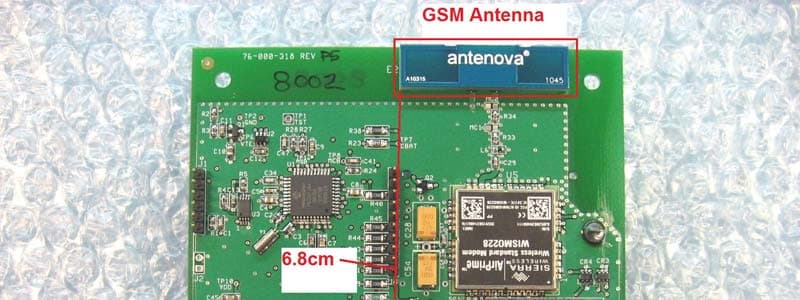
RWBMT9100CTM
Jun 23, 2011Tank Monitoring System
Equipment Class
DTS - Digital Transmission System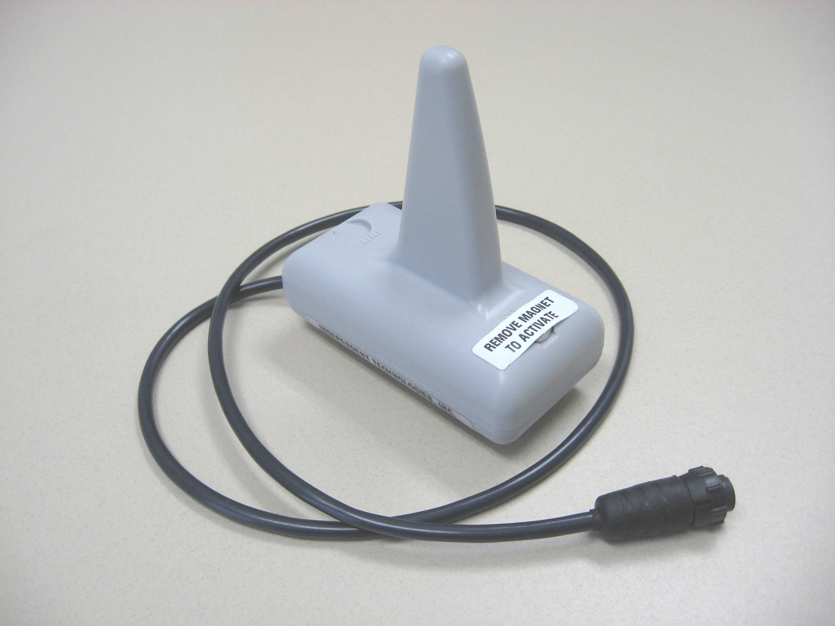
RWBMT9100TNK
Oct 17, 2007Fuel Tank Level Transmitter
Equipment Class
DTS - Digital Transmission System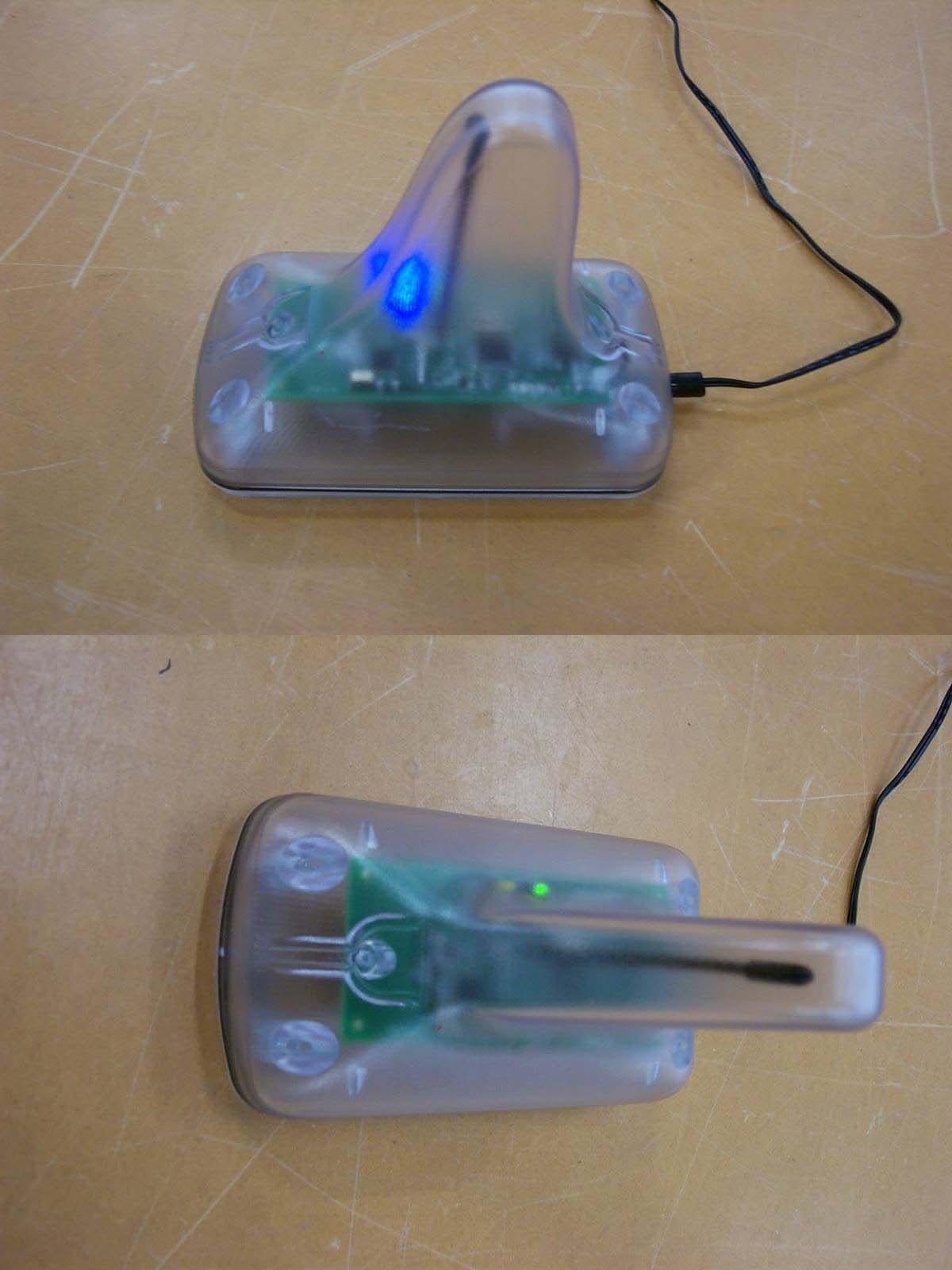
RWB-MT9100R
Aug 30, 2006ESROC RMS Repeater
Equipment Class
DTS - Digital Transmission System