RWBMT9103CBUCellular Tank Monitor
MetroTel Corp of Minnesota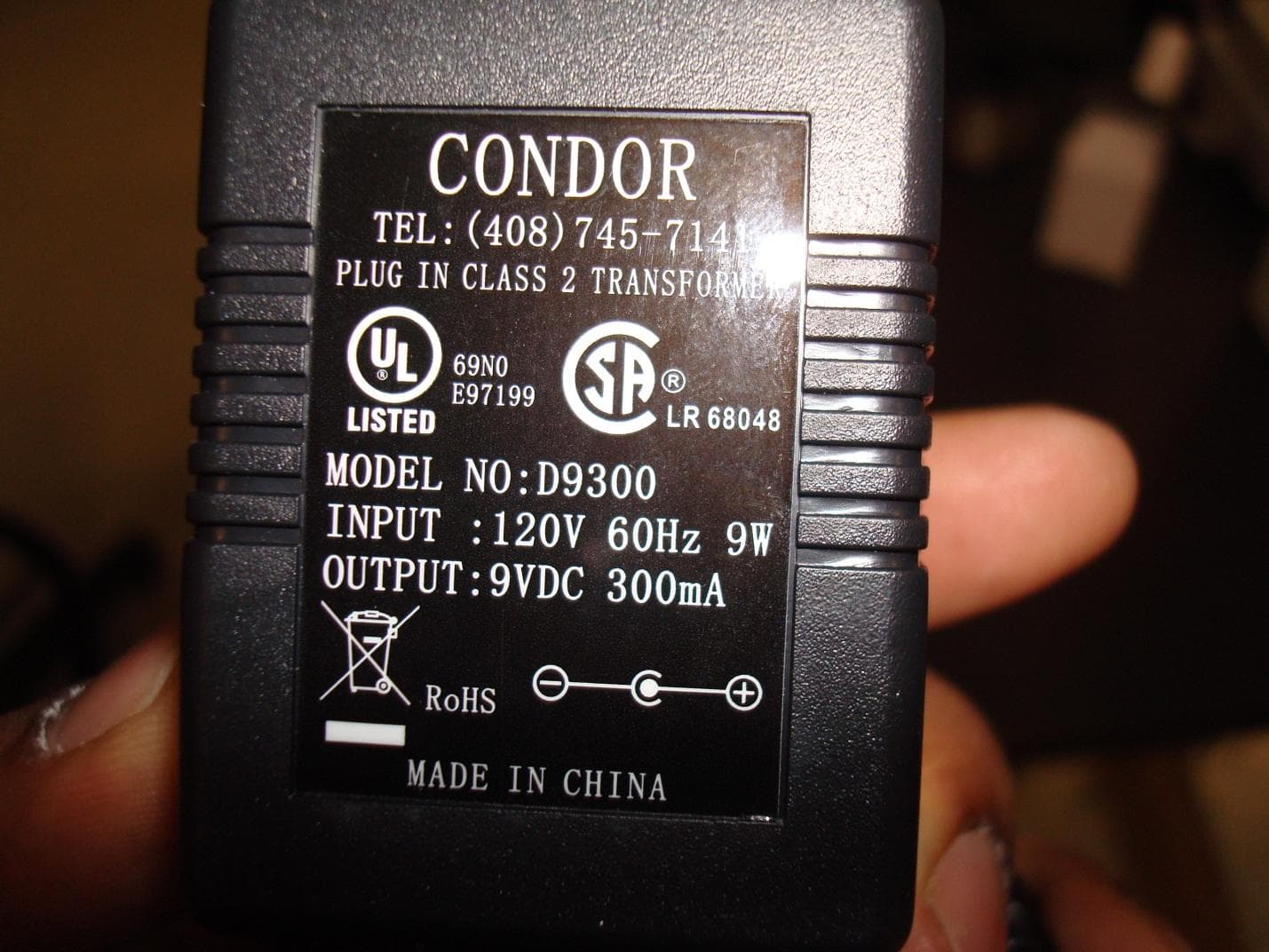
Click to zoom
Application Details
- Equipment Class
- DTS - Digital Transmission System
- Date of Grant
- Dec 30, 2014
- Application Purpose
- Original Equipment
- Date of Application
- Dec 30, 2014
- Equipment Note
- Cellular Tank Monitor
- Frequency Range
- 912.00000000 - 921.00000000
- Company
- MetroTel Corp of Minnesota
- Country
- United States
Documents & Files
Document Text
Text extracted from the exhibit documents filed with the FCC. Open a document above to read the original.
Users Manual
OVERVIEW The WESROC ® Route Management System has been installed by your service provider. The tank transmitter measures the tank level and will transmit the tank level to the Base Unit whenever the level changes. The Base Unit allows you to observe your tank level from the comfort of your home, and it will periodically send your tank level to your service provider. WESROC ® RMS allows your service provider to supply you with the fastest and most accurate service possible. Never again will you have to go outside to check your tank level, nor will you wonder if your service provider knows the level of your tank, because now they do. The WESROC ® Route Management System will not interfere with other wireless devices in your home. The BASE UNIT must remain connected AC POWER in order for WESROC ® RMS to provide accurate tank levels to your service provider. It is imperative that you DO NOT RELOCATE OR UNPLUG any WESROC ® RMS device without first contacting your service provider to ensure uninterrupted service. WESROC ® Route Management System (RMS) Cellular Base User’s Guide You’ll Never Run Out of Propane Tank Transmitter Cellular Base Unit Page 2 THIS GUIDE COVERS • Safety Instructions • Features • Installation of the WESROC ® RMS Deluxe Base Unit o Selecting a Location o Connecting Power • Operation of the WESROC ® RMS Deluxe Base Unit o Operational Overview o Power Up o Level Display o Digital Clock Display and Settings o Temperature Display o Display Brightness Adjustment and Temperature Scale Settings • Certifications • Specifications • Warranty • Troubleshooting SAFETY INSTRUCTIONS • Read all instructions prior to operation. • Unplug the Base Unit from the wall outlet before cleaning. • Use a damp cloth for cleaning. • Do not use the Base Unit near water. • Place the Base Unit on a secure and stable surface. • Do not rest anything on the power. Keep cords hidden and secure so they do not pose a trip hazard. • Do not overload wall outlets or extension cords as this can result in a fire or electrical shock. • Do not disassemble any WESROC ® RMS device because this will void the warranty and may expose you to dangerous voltages or other risks. • Disconnect the Base Unit if a cord becomes damaged or frayed. • Do not use the Base Unit if there is a known gas leak. • The Base Unit is intended for INDOOR USE ONLY. IMPORTANT : Only use the power adapter provided. Using another adapter could seriously damage the Base Unit. Page 3 FEATURES • A large, bright display that can be easily read from across the room. The display can be adjusted to the appropriate brightness level for various lighting conditions or an auto-off feature can be selected which will automatically turn off the display after about 4 minutes of no activity. • The Base Unit’s electronics are housed in a durable enclosure, which can be tilted to accommodate different mounting configurations. The Base Unit can sit on a flat surface or be wall mounted. • If your tank level reaches a predetermined level, the Base Unit will immediately notify your propane supplier. • With the Auto-Update (AUTO) feature enabled, you will never need to set the time after a power failure or during daylight savings time changes. The Base Unit will automatically set the time when it sends your tank level to your service provider. • The indoor and outdoor (external temperature transmitter required) temperature can be displayed in either Fahrenheit or Celsius. • A Transmitter Activity Indicator is included in the Base Unit. The LED in the lower, right corner lights up when a transmitter is sending new information to the Base Unit. INSTALLATION of the WESROC ® RMS DELUXE BASE UNIT • The following are several items that will help you and your service provider determine the best location for the Base Unit: o Visibility: The Base Unit should be located where it is easy to view and access. o Power: The Base Unit requires 110V - AC to operate and should be placed near an electrical outlet. Make sure that the AC outlet is not connected through a switch because the Base Unit must be plugged into constant AC power to work correctly. o Temperature Accuracy: If you plan on using the indoor temperature display, the Base Unit should NOT be placed in direct sunlight, nor should it be placed near any heating or cooling source. o Tank Location: For best results, the Base Unit should be placed as close to the tank as possible. This may not always be possible, but your service provider will be able to determine if the location you have chosen will be adequate for proper operation. • Once an acceptable location for your Base Unit has been chosen, your service provider will complete the installation. IMPORTANT : If you choose to relocate your Base Unit, please contact your service provider prior to doing so. This will allow them to ensure continued operation of your system. Page 4 OPERATION of the WESROC ® RMS DELUXE BASE UNIT Operational Overview • The Base Unit has three pushbutton switches on the top: o The single button on the left-hand side is the MODE button. o The center button is the DOWN ▼ arrow. o The right-hand button is the UP ▲ arrow. • The MODE button toggles the display between Tank Level, Time, and Temperature displays. The UP/DOWN arrow buttons select which tank/transmitter is displayed. Power Up • When the Base Unit is first powered on, all of the display segments, icons, and LEDs will be illuminated for about two seconds. This is done to ensure all display components are working properly. The Base Unit will then return to the mode that was last selected prior to power loss. Tank Level Display • This mode is indicated by the illumination of a % symbol on the right side of the display. The number on the left is the tank transmitter number, and the number on the right is the tank level. If more than one tank is being monitored, the UP/DOWN arrow buttons may be used to scroll through the tank list. Your service provider has left you a notification on the back …
Text truncated - open the document above for the full version.
Attestation Statements
Nebraska Center for Excellence in Electronics 4740 Discovery Drive Lincoln, NE 68521 Phone: 402.323.6233 Fax: 402.323.6238 Attestation Date: 2014 DECEMBER 15 Subject: Attestation for: FCC ID: RWBMT9103CBU, IC:115A-MT9103CBU I would like to hereby attest that the WESROC RMS 3G Cellular Base Unit, model MT-9100CBU does not contain any provisions for connection to a network via Ethernet or telecom ports. The plastic enclosure provided for testing included holes marked for these purpose, but the device tested as intended to be certified did not have the functionality. Note: The “Line” and “Phone” ports as shown above WILL NOT be present on the final enclosure design. Sincerely, By: __________________________ Nic Johnson, EMC Electrical Test Engineering Manager, NCEE Labs_________ (Signature/Title 1 ) (Print name) 1 - Must be signed by applicant contact given for applicant on the FCC site, or by the authorized agent if an appropriate authorized agent letter has been provided. Letters should be placed on appropriate letterhead.
Cover Letter(s)
26 First Avenue S.E. New London, MN. 56273 Phone (320) 354-2929 Fax (320) 354-5827 www.metrotelcorp.com May 8, 2014 American Telecommunications Certification Body, Inc. 6731 Whittier Avenue Suite C110 McLean, VA. 22101 Re: Letter of Agency for MetroTel Corporation of Minnesota. To whom it may concern: Greetings, Please be advised that MetroTel Corporation of Minnesota authorizes Nic Johnson of The Nebraska Center for Excellence in Electronics to act on our behalf with respect to the Federal Communications Commission in all matters relating to certification of equipment under Part 15 of the FCC Rules until further notice. We further certify that no party (as defined in 1.2002 of CFR 47, 1992) to this application, including myself, is subject to a denial of federal benefits, that includes FCC benefits, pursuant to Section 5301 of the Anti-Drug Abuse Act of 1988, 21 U.S.C., 862. Regards, Doug Ferguson Director of Engineering Director of Quality Assurance MetroTel Corporation of Minnesota P.O. Box 270 26 First Avenue S.E. New London, MN. 56273 320-354-2929
Cover Letter(s)
Nebraska Center for Excellence in Electronics 4740 Discovery Drive Lincoln, NE 68521 Phone: 402.323.6233 Fax: 402.323.6238 Request for Confidentiality Date: 2014 DECEMBER 16 Subject: Confidentiality Request for: FCC ID: RWBMT9103CBU, IC:115A-MT9103CBU Pursuant to FCC 47 CRF 0.457(d) and 0.459 and IC RSP-100 Issue 10, Section 6.4, the applicant requests that a part of the subject FCC application be held confidential. Type of Confidentiality Requested Exhibit Short Term Permanent Block Diagrams Short Term Permanent Operation Description/Theory of Operation Short Term Permanent Schematics Short Term Test Setup Photos MetroTel Corporation of Minnesota has spent substantial effort in developing this product and it is one of the first of its kind in industry. Having the subject information easily available to "competition" would negate the advantage they have achieved by developing this product. Not protecting the details of the design will result in financial hardship. Permanent Confidentiality: The applicant requests the exhibits listed above as permanently confidential be permanently withheld from public review due to materials that contain trade secrets and proprietary information not customarily released to the public. Short-Term Confidentiality: The applicant requests the exhibits selected above as short term confidential be withheld from public view for a period of ___(specify number of days not to exceed 180) 1 ___ days from the date of the Grant of Equipment Authorization and prior to marketing. This is to avoid premature release of sensitive information prior to marketing or release of the product to the public. Applicant is also aware that they are responsible to notify ACB in the event information regarding the product or the product is made available to the public. ACB will then release the documents listed above for public disclosure pursuant to FCC Public Notice DA 04-1705. NOTE for Industry Canada Applications: The applicant understands that until such time that IC distinguishes between Short Term and Permanent Confidentiality, either type of marked exhibit above will simply be marked Confidential when submitted to IC. Sincerely, By: __________________________ Nic Johnson, EMC Electrical Test Engineering Manager, NCEE Labs_________ (Signature/Title 2 ) (Print name) 1 - Please refer to http://acbcert.com/documents/misc-docs/Memo-Short-Term-Vs-Standard-Confidentiality.pdf for complete details. 2 - Must be signed by applicant contact given for applicant on the FCC site, or by the authorized agent if an appropriate authorized agent letter has been provided. Letters should be placed on appropriate letterhead.
External Photos
External Photos FCC ID: RWBMT9103CBU IC: 115A-MT9103CBU Page 1 of 5 Figure 1 - Front External Photos FCC ID: RWBMT9103CBU IC: 115A-MT9103CBU Page 2 of 5 Figure 2 - Top External Photos FCC ID: RWBMT9103CBU IC: 115A-MT9103CBU Page 3 of 5 Figure 3 - Bottom External Photos FCC ID: RWBMT9103CBU IC: 115A-MT9103CBU Page 4 of 5 Figure 4 – Back *Note: The ports marked “Line” and “Phone” will not be present on the final enclosure design. This product does not have any provisions for connecting to a Telecom network. External Photos FCC ID: RWBMT9103CBU IC: 115A-MT9103CBU Page 5 of 5 Figure 5 - Power Supply
Internal Photos
Internal Photos FCC ID: RWBMT9103CBU IC: 115A-MT9103CBU Page 1 of 7 Figure 1 - Front Side Figure 2 - Back Side Internal Photos FCC ID: RWBMT9103CBU IC: 115A-MT9103CBU Page 2 of 7 Figure 3 - Front Side Internal Photos FCC ID: RWBMT9103CBU IC: 115A-MT9103CBU Page 3 of 7 Figure 4 - Front Left Side Detail Internal Photos FCC ID: RWBMT9103CBU IC: 115A-MT9103CBU Page 4 of 7 Figure 5 - Front Sid Center Detail Internal Photos FCC ID: RWBMT9103CBU IC: 115A-MT9103CBU Page 5 of 7 Figure 6 - Front Right Side Detail Internal Photos FCC ID: RWBMT9103CBU IC: 115A-MT9103CBU Page 6 of 7 Figure 7 - Front Center Detail Internal Photos FCC ID: RWBMT9103CBU IC: 115A-MT9103CBU Page 7 of 7 Figure 8 - Front Center Detail
RF Exposure Info
Page 1 of 2 FCC ID: RWBMT9103CBU IC:115A-MT9103CBU Maximum exposure limits from CFR 47, FCC Part 1.1310: Table 1—Limits for Maximum Permissible Exposure (MPE) Frequency range (MHz) Electric field strength (V/m) Magnetic field strength (A/m) Power density (mW/cm 2 ) Averaging time (minutes) (A) Limits for Occupational/Controlled Exposure 0.3-3.0 614 1.63 *100 6 3.0-30 1842/f 4.89/f *900/f 2 6 30-300 61.4 0.163 1.0 6 300-1,500 f/300 6 1,500-100,000 5 6 (B) Limits for General Population/Uncontrolled Exposure 0.3-1.34 614 1.63 *100 30 1.34-30 824/f 2.19/f *180/f 2 30 30-300 27.5 0.073 0.2 30 300-1,500 f/1500 30 1,500-100,000 1.0 30 The power density is calculated as shown below: S = (P x G)/(4 x π x d^2) – used to calculate exposure at 20 cm S= power density P = transmitter conducted power (in mW) G = antenna numeric gain D = distance to radiation center (20 cm) Page 2 of 2 Table 2 – Power Density Calculations Frequency Antenna Gain Output Power Minimum Seperation Distance Power Density Limit MHz numerical mW cm mW/cm^2 mW/cm^2 912.00 1.64 2.81 0.67 0.0009173 0.0608 916.50 1.64 2.72 0.53 0.0005414 0.0611 921.00 1.64 2.72 0.53 0.0005414 0.0614 Note: This equipment is not intended to be operated by hand. It is expected that a 20cm separation will be maintained at all times. All measurements were taken from direct conducted measurements on the antenna port.
Test Report
Nebraska Center for Excellence in Electronics 4740 Discovery Drive Lincoln, NE 68521 Phone: 402.323.6233 Fax: 402.323.6238 Amended Test Report Company: MetroTel Corp 26 First Ave SE New London, MN 56273 Product: Cellular Base Unit FCC ID: RWBMT9103CBU IC : 115A-MT9103CBU Test Report No: R20131004-20A APPROVED BY: _________________________ Nic Johnson Technical Manager iNARTE Certification EMC-003337-NE DATE: 16 December 2014 Total Pages: 41 The Nebraska Center for Excellence in Electronics (NCEE) authorizes the above named company to reproduce this report provided it is reproduced in its entirety for use by the company’s employees only. Any use that a third party makes of this report, or any reliance on or decisions made based on it, are the responsibility of such third parties. NCEE accepts no responsibility for damages, if any, suffered by any third party as a result of decisions made or actions based on this report. This report applies only to the items tested. NCEE is a FCC and Industry Canada registered lab. FCC #100875, IC #4294 NCEE Labs R201310004-20A FCC ID: RWBMT9103CBU IC: 115A-MT9103CBU Page 2 of 40 1.0 Summary of test results 1.1 Reason for amendment 2.0 Description 2.1 Equipment under test 2.2 Laboratory description 2.3 Description of test modes 2.4 Applied standards 2.5 Description of support units 2.6 Configuration of system under test 3.0 Test equipment used 4.0 Detailed Results 4.1 Unique antenna requirement 4.2 Radiated Emissions 4.3 Conducted AC Mains Emissions 4.4 Bandwidth 4.5 Maximum peak output power 4.6 Power spectral density (PSD) 4.7 Bandedges Appendix A – Test photos Appendix B – Sample calculation Table of figures Figure 1 - AC/DC Power Supply ...................................................................................... 6 Figure 2 - Radiated Emissions Test Setup .................................................................... 10 Figure 3 - Radiated Emissions Plot, Ch. 1 ..................................................................... 11 Figure 4 - Radiated Emissions Plot, Ch. 2 ..................................................................... 13 Figure 5 - Radiated Emissions Plot, Ch. 3 ..................................................................... 15 Figure 6 - Radiated Emissions Plot– Receive Mode ...................................................... 17 Figure 7 - Conducted Emissions Test Setup ................................................................. 20 Figure 8 - Conducted Emissions Plot ............................................................................ 21 Figure 9 - 6dB Bandwidth .............................................................................................. 23 Figure 10 - 99% Occupied Bandwidth ........................................................................... 24 Figure 11 - 6dB Bandwidth ............................................................................................ 25 Figure 12 - 99% Occupied Bandwidth ........................................................................... 26 Figure 13 - 6dB Bandwidth ............................................................................................ 27 Figure 14 - 99% Occupied Bandwidth ........................................................................... 28 Figure 15 - Power Spectral Density Measurement, Ch. 1 .............................................. 32 Figure 16 - Power Spectral Density Measurement, Ch. 2 .............................................. 33 Figure 17 - Power Spectral Density Measurement, Ch. 3 .............................................. 34 Figure 18 – Lower Band-edge Measurements ............................................................... 36 Figure 19 –Higher Band-edge Measurements ............................................................... 37 Figure 20 - Radiated Emissions Test Setup .................................................................. 38 Figure 21 - Radiated Emissions Test Setup .................................................................. 38 Figure 22 - Conducted Emissions Test Setup ............................................................... 39 Figure 23 - Conducted Emissions Test Setup ............................................................... 39 NCEE Labs R20131004-20A FCC ID: RWBMT9103CBU IC:115A-MT9103CBU Page 3 of 40 1.0 Summary of test results The EUT has been tested according to the following specifications: APPLIED STANDARDS: FCC Part 15, Subpart C Standard Section Test Type and Limit Result Remark 15.203 Unique Antenna Requirement Pass Antenna soldered to PCB 15.207 Conducted Emissions Pass Meets the requirement of the limit. 15.209 Radiated Emissions Pass Meets the requirement of the limit. 15.247(a)(2) Minimum Bandwidth, Limit: Min. 500kHz Pass Meets the requirement of the limit. 15.247(b) Maximum Peak Output Power, Limit: Max. 30dBm Pass Meets the requirement of the limit. 15.247(c) Transmitter Radiated Emissions, Limit: Table 15.209 Pass Meets the requirement of the limit. 15.247(d) Power Spectral Density, Limit: Max. 8dBm Pass Meets the requirement of the limit. 15.247(c) Band Edge Measurement, Limit: 20dB less than the peak value of fundamental frequency Pass Meets the requirement of the limit. 1.1 Reason for amendment The EUT name was updated to MT-9103-CBU. The device did not change and only the name is different. NCEE Labs R20131004-20A FCC ID: RWBMT9103CBU IC:115A-MT9103CBU Page 4 of 40 2.0 Description 2.1 Equipment under test The Equipment Under Test (EUT) was a Cellular Base Unit (MT-9103-CBU). It operates in the 902 – 928 MHz band. The EUT also contains a pre-approved transmitter (FCC ID:RI7HE910NA, IC:5131A-HE910NA). It is a GSM Quad-band cellular module with modular approval. EUT Received Date: 19 March 2014 EUT Tested Date: 19 March 2014- 20 March 2014 NOTE: 1. For more detailed features description, please refer to the manufacturer's specifications or User's Manual. 2.2 Laboratory description All testing was performed at the …
Text truncated - open the document above for the full version.
Test Setup Photos
Test Setup Photos FCC ID: RWBMT9103CBU IC: 115A-MT9103CBU Page 1 of 2 Figure 1 - Radiated Emissions Test Setup Figure 2 - Radiated Emissions Test Setup Test Setup Photos FCC ID: RWBMT9103CBU IC: 115A-MT9103CBU Page 2 of 2 Figure 3 - Conducted Emissions Test Setup Figure 4 - Conducted Emissions Test Setup
Contact Information
Applicant
Kripa Sharma
Technical Contact
MetroTel Corp. of MinnesotaDoug Ferguson
[email protected]3203542929
26 First Ave S.E. · New London, Minnesota · United States
Test Firm
Nebraska Center for Excellence in ElectronicsNic Johnson
Technical Specifications
| # | Rule Parts | Frequency Range | Power Output |
|---|---|---|---|
| 1 | 15C | 912 MHz - 921 MHz | 3.00 mW |
Other Applications from MetroTel Corp of Minnesota
RWBMT9100CTM
Jun 23, 2011Tank Monitoring System
Equipment Class
DTS - Digital Transmission System
RWBMT9100TNK
Oct 17, 2007Fuel Tank Level Transmitter
Equipment Class
DTS - Digital Transmission System
RWB-MT9100R
Aug 30, 2006ESROC RMS Repeater
Equipment Class
DTS - Digital Transmission System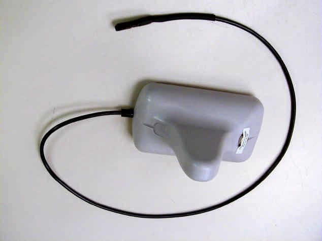
RWB-MT9100T
Mar 28, 2004WESROC RMS Transmitter MT-9100T
Equipment Class
DXX - Part 15 Low Power Communication Device Transmitter