RWBMT9100CTMTank Monitoring System
MetroTel Corp of Minnesota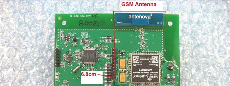
Click to zoom
Application Details
- Equipment Class
- DTS - Digital Transmission System
- Date of Grant
- Jun 23, 2011
- Application Purpose
- Original Equipment
- Date of Application
- Jun 22, 2011
- Equipment Note
- Tank Monitoring System
- Frequency Range
- 916.48000000 - 916.48000000
- Company
- MetroTel Corp of Minnesota
- Country
- United States
Documents & Files
Document Text
Text extracted from the exhibit documents filed with the FCC. Open a document above to read the original.
Users Manual
72-70-164, Rev. P4 06/16/2011 WESROC ® RMS Cellular Tank Monitor Model MT-9100CTM Operation Manual WESROC ® RMS Cellular Tank Monitor - Operation Manual - Independent Technologies, Inc. 72-70-164, Rev. P4 Page 2 06/16/2011 Table of Contents Safety Information.......................................................................................................................................................4 Hazardous Environments ........................................................................................................................... 4 Battery Replacement.................................................................................................................................. 4 Radio Frequency Exposure ........................................................................................................................ 4 Radio Frequency Interference.................................................................................................................... 4 Overview.......................................................................................................................................................................5 Device Characteristics ............................................................................................................................... 5 Installation ................................................................................................................................................. 5 Power ......................................................................................................................................................... 5 Installation....................................................................................................................................................................6 Mounting Location .................................................................................................................................... 6 Tank Gauge................................................................................................................................................ 6 Cellular Signal ........................................................................................................................................... 6 Host Information........................................................................................................................................ 7 Installation Steps........................................................................................................................................ 7 Operation......................................................................................................................................................................9 General....................................................................................................................................................... 9 Operating Modes ....................................................................................................................................... 9 OFF Mode:.............................................................................................................................. 9 NORMAL Mode: .................................................................................................................... 9 INITIALIZATION Mode: .................................................................................................... 10 CONFIGURATION Mode: .................................................................................................. 10 Reporting To Host ................................................................................................................................... 10 Tank Level Measurement ........................................................................................................................ 11 Tank Level Events and Conditions .......................................................................................................... 11 Tank Fill Event: .................................................................................................................... 11 Tank Draw Event: ................................................................................................................. 11 Tank Level Change Event:.................................................................................................... 11 Tank Critical High Condition: .............................................................................................. 11 Tank Warning High Condition: ............................................................................................ 11 Tank Warning Low Condition: ............................................................................................. 11 Tank Critical Low Condition: ............................................................................................... 12 Missing Sensor Condition: .................................................................................................... 12 Temperature Alarms ................................................................................................................................ 12 Low Battery Notification ......................................................................................................................... 12 Portable Diagnostic Unit ...........................................................................................................................................13 General..................................................................................................................................................... 13 PDU Screen Map ..................................................................................................................................... 13 PDU Screens ......................................................................................................…
Text truncated - open the document above for the full version.
Cover Letter(s)
022311 – 6 Request for Confidentiality Date: 6/20/2011 Subject: Confidentiality Request for: FCC ID:RWB-MT9100CTM, IC:116A-MT9100CTM Pursuant to FCC 47 CRF 0.457(d) and 0.459 and IC RSP-100, Section 10, the applicant requests that a part of the subject FCC application be held confidential. Type of Confidentiality Requested Exhibit Short Term Permanent Block Diagrams Short Term External Photos Short Term Permanent* 2 Internal Photos Short Term Permanent Operation Description/Theory of Operation Short Term Permanent Schematics Short Term Test Setup Photos Short Term Permanent* User’s Manual *Note: ______(Insert Explanation as Necessary)______ Permanent Confidentiality: The applicant requests the exhibits listed above as permanently confidential be permanently withheld from public review due to materials that contain trade secrets and proprietary information not customarily released to the public. Short-Term Confidentiality: The applicant requests the exhibits selected above as short term confidential be withheld from public view for a period of ___(specify number of days not to exceed 180 ) 3 ___ days from the date of the Grant of Equipment Authorization and prior to marketing. This is to avoid premature release of sensitive information prior to marketing or release of the product to the public. Applicant is also aware that they are responsible to notify ACB in the event information regarding the product or the product is made available to the public. ACB will then release the documents listed above for public disclosure pursuant to FCC Public Notice DA 04-1705. NOTE for Industry Canada Applications: The applicant understands that until such time that IC distinguishes between Short Term and Permanent Confidentiality, either type of marked exhibit above will simply be marked Confidential when submitted to IC. Sincerely, By: __________________________ Nic Johnson, Test Engineer, NCEE Labs (Signature/Title 4 ) (Print name) 2 - The asterisked items (*) require further justification before permanent confidentiality will be allowed. These also currently require review by the FCC under their Permit-But-Ask policy before the grant is issued and can delay completion of an application. Further justification should be added to the note above. One such example for a potted device would be: “The EUT is FULLY potted using a non-removable epoxy based material. Removal of potting material causes irreparable damage to internal circuitry. See photographs exhibits that outline the device before and after potting.” 3 - Please refer to http://acbcert.com/documents/misc-docs/Memo-Short-Term-Vs-Standard-Confidentiality.pdf for complete details. 4 - Must be signed by applicant contact given for applicant on the FCC site, or by the authorized agent if an appropriate authorized agent letter has been provided. Letters should be placed on appropriate letterhead.
Cover Letter(s)
26 First Avenue S.E. New London, MN. 56273 Phone (320) 354-2929 Fax (320) 354-5827 www.metrotelcorp.com June 14, 2011 Re: Ownership of the Wesroc® Trademark To whom it may concern: Greetings, This letter is an attestation of the ownership of the Wesroc® trademark. The Wesroc® trademark (United States Patent and Trademark office serial number 74034269 ) was filed with the USPTO on March 5, 1990 and is wholly owned by Independent Technologies, Inc. Metrotel Corporation of Minnesota is wholly owned by Independent Technologies and has been given full rights to the use of the Wesroc® trademark. Regards, Doug Ferguson Director of Engineering Director or Quality Assurance MetroTel Corporation of Minnesota New London, MN. 56273 320-354-2929
Cover Letter(s)
NCEE Labs FCC ID:RWBMT9100CTM IC:115A‐MT9100CTM 21 June 2011 NCEE Labs Response to ACB comments from June 15, 2011 NCEE Labs responses are in blue. 1. Please provide 15.19 statement in user manual. This device complies with part 15 of the FCC Rules. Operation is subject to the following two conditions: (1) This device may not cause harmful interference, and (2) this device must accept any interference received, including interference that may cause undesired operation. A revised manual has been provided. Please see “WRMS Cellular Tank Monitor – Operation Manual RevP4 – 2011‐06‐16.pdf” 2. You have listed internal photos as confidential. This will require a PBA with the FCC which will add a fee to the application. You might also have to have a NDA in place to show how you are going keep these photos confidential. Please see attachment concerning internal photo confidentiality. The internal photos are no longer requested to be held confidential. Please see “MT9100CTM‐ Confidentiality Request rev2.pdf” 3. Please show where the GSM transmitter is located in respect to the ISM transmitter if their antennas are closer than 5cm we will need to have investigate if SAR testing for co‐location configuration is needed or not. Also if these two transmitters are capable of transmitting simultaneously we need that documented in the test report showing the ISM was tested while the GSM was transmitting or we need a statement that they do not transmit at the same time. “Disregard initial question for number 3. What we will need is something showing the antenna location with respect to each transmitter and if they are within 20cm as stated in the user manual then we will need a MPE report justifying co‐location.” A new Functional Description document has been provided, stating that the transmitter are not permitted to transmit simultaneously. Please see Section 3.1, paragraph 2 of “WRMS Cellular Tank Monitor ‐ Functional Description RevB ‐ 2011‐06‐16.pdf” A revised internal photo exhibit has been included to show the location of the antennas and the distance between them. Please see “MT9100CTM Internal Photo Exhibit rev2.pdf” 4. On the form 731 you state this is a composite application please explain how this is a composite application as there is only one test report for DTS that was uploaded. NCEE Labs FCC ID:RWBMT9100CTM IC:115A‐MT9100CTM The 731 form has been revised to state that it is not a composite device. Please see “RWB‐ MT9100CTM‐Form‐731 rev2.pdf” 5. As this will be a classified as portable because of the 60/frequency threshold the EUT should be tested in the X, Y and Z axis. If this was done please state that it was in the test report. An amended test report has been provided with additional description on the EUT test setup. Please see “R060311‐40A.pdf” 6. In the test report the 6dB bandwidth plot does not show the delta of 655.31kHz please show a plot that fits this data. An amended test report has been provided with a 6dB bandwidth plot included. Please see “R060311‐40A.pdf” 7. For Industry Canada the Canadian representative letter must be signed by the Canadian Rep and also show their company number. Please revise the Rep letter to include this. A new Canadian representative letter has been provided with a signature by the Canadian representative and their Canadian company number included. Please see “Westel_IC2.pdf” 8. For Industry Canada the REL letter is from 2009 these letter are only good for one year from issue date please upload a more recent REL letter. An updated letter has been provided. Please see “ATCB IC Ack of Listing Reqs rev2.pdf”. 9. The IC application form must have the Canadian Rep company number filled in please revise to include this number. The IC application has been revised to include this number. Please see “115A‐MT9100CTM‐IC Form rev 2.pdf” 10. For the IC application on page two at the top the type of equipment must be included if you are having trouble with this form please download the latest form from our website under forms and docs. The IC application has been revised to include this information. Please see “115A‐MT9100CTM‐ IC Form rev 2.pdf” 11. I notice you have two powers listed one for watts conducted and one for field strength please list conducted power only if the power listed is for the same transmitter if they are not the same transmitter then please explain. The IC application has been revised so as to not include the field strength levels. Only the conducted power is included. Please see “115A‐MT9100CTM‐IC Form rev 2.pdf” 12. IC application listed model number does not match the model number on the label please confirm which is correct and revise the application form or label. NCEE Labs FCC ID:RWBMT9100CTM IC:115A‐MT9100CTM An updated label exhibit has been provided. The new labels read “MT‐9100CTM”. The S10 suffix is included, but with a space after the model number, to indicate that it is not part of the model number. Please see “WRMS Cellular Tank Monitor Labels RevP2.pdf” 13. The unique product number on the IC application does not match the UPN on the label. Please confirm which is correct and revise accordingly. See the response to number 12. Nic Johnson Test Engineer NCEE Labs 402‐472‐5880 [email protected]
External Photos
NCEE Labs External Photos Exhibit FCC ID:RWBMT9100CTM IC:115A‐MT9100CTM Figure 1 ‐ External Photo 1 Figure 2 – External Photo 2 NCEE Labs External Photos Exhibit FCC ID:RWBMT9100CTM IC:115A‐MT9100CTM Figure 3 ‐ External Photo 3
ID Label/Location Info
MT-9100CTM Cellular Tank Monitor - Enclosure Labeling Model MT-9100CTM R evision P2 (Scale = 2:1) - Page 1 of 2 Identification Label Independent Technologies, Inc. 0 6/16/2011 3.50in. 0.50in. Print on Brady B486 metalized polyester label stock. Print using Brady 4300 Series thermal transfer ribbon. INDEPENDENT TECHNOLOGIES, INC. OMAHA, NE - www.IndependentTech.com - PATENTS PENDING CELLULAR TANK MONITOR: MT - 9100CTM S10 IMSI: 000000000000000; H/W: 5; F/W: 3-2; T/C: 001821 S/N: 000080 00008000008000008005 050505 Safety Certification Label 3.50in. 0.50in. GROUPS C&D HAZARDOUS (CLASSIFIED) LOCATIONS PER ANSI/UL913 AND CAN/CSA C22.2 NO. 157; NO USER MAINTENANCE ORREPAIR - SEE DATA SHEET; TEMP CODE T4;INTRINSICALLY SAFE DEVICE - SECURITE INTRINSEQUE - ExiaTANK MONITORING EQUIPMENT FOR USE IN CLASS I, DIVISION 1, 19WU -40C Tamb +60C; LISTED US C U L R Independent Technologies, Inc. 06/16/2011 2.00in. 1.25in. Print using Brady 4300 Series thermal transfer ribbon. MT-9100CTM Cellular Tank Monitor - Enclosure Labeling M odel MT-9100CTM Rev ision P2 (Scale = 2:1) - Page 2 of 2 FCC ID: RWBMT9100CTM IC: 115A-MT9100CTM Battery Pack and FCC/IC ID Label DEVICE COMPLIES WITH PART 15 OF THE FCC RULES. INDEPENDENT TECHNOLOGIES, INC. INTRINSICALLY SAFE BATTERY PACK MODEL: MT-9100 CTM 3.6VDC, 8500mAHr SAFE TO REPLACE IN HAZARDOUS AREAS DO NOT CRUSH OR INCINERATE! (SEE DATA SHEET) Print on Brady B486 metalized polyester label stock. GSM MODULE FCC ID: N7NWISMO228 IC: 2417C-WISMO228 Label Location
Internal Photos
NCEE Labs Internal Photos Exhibit FCC ID:RWBMT9100CTM IC:115A‐MT9100CTM Figure 1 ‐ Internal Photo of circuit board with potting Figure 2 ‐ Internal Photo showing back of circuit board and capacitor NCEE Labs Internal Photos Exhibit FCC ID:RWBMT9100CTM IC:115A‐MT9100CTM Figure 3 ‐ Internal Photo with Potting Removed Figure 4 ‐ Internal Photo showing GSM and ISM antennas and distance between
RF Exposure Info
Nebraska Center for Excellence in Electronics 4740 Discovery Drive Lincoln, NE 68521-5376 Phone: 402.472.5880 Fax: 402.472.5881 Nebraska Center for Excellence in Electronics 4740 Discovery Drive Lincoln, NE 68521-5376 Phone: 402.472.5880 Fax: 402.472.5881 Page 1 of 1 14 June 2011 RF exposure calculation for FCC ID:RWBMT9100CTM, IC ID:115A-MT9100CTM RF Exposure Calculations: This device meets the output power threshold in KDB 447498 of 60/f(GHz) in which case no SAR or RF exposure evaluation is required. RF Power Measurement The RF power measurement was taken from NCEE test report R060311-40. Frequency (MHz) Output Power dBm Output Power mW 916.48MHz 6.88 4.87 Power Limit = 60/f (mW) 65.468 Frequency (f) (GHz) 0.916 Maximum peak output power (mW) 1 18.160 Notes: 1. Output power was measured in peak output power. Because it can be assumed that the time- averaged output power as specified in KDB 447498 will be less than a peak output power, compliance with the limit can be presumed. References: 1. FCC OET Bulletin 65, Edition 97-01 2. FCC Supplement C to OET Bulletin 65, edition 01-01 3. IEEE C95.1, 1999 4. KDB 447498
Test Report
Nebraska Center for Excellence in Electronics 4740 Discovery Drive Lincoln, NE 68521-5376 Phone: 402.472.5880 Fax: 402.472.5881 Nebraska Center for Excellence in Electronics 4740 Discovery Drive Lincoln, NE 68521-5376 Phone: 402.472.5880 Fax: 402.472.5881 Amended Test Report Company: MetroTel Corp 26 First Ave SE New London, MN 56273 Contact: Jim Fangmeier Product: WESROC RMS Cellular Tank Monitor FCC ID: RWBMT9100CTR IC : 115A-MT9100CTM Test Report No: R060311-40A APPROVED BY: Nic Johnson _________________________ Test Engineer, iNARTE Certification EMC-003337-NE DATE: 21 June 2011 Total Pages: 28 The Nebraska Center for Excellence in Electronics (NCEE) authorizes the above named company to reproduce this report provided it is reproduced in its entirety for use by the company’s employees only. Any use that a third party makes of this report, or any reliance on or decisions made based on it, are the responsibility of such third parties. NCEE accepts no responsibility for damages, if any, suffered by any third party as a result of decisions made or actions based on this report. This report applies only to the items tested. NCEE is a FCC and Industry Canada registered lab. FCC #100875, IC #4294 NCEE Labs R060311-40A FCC ID: RWBMT9100CTM IC: 115A-MT9100CTM Page 2 of 28 1.0 Summary of test results 2.0 Description 2.1 Equipment under test 2.2 Laboratory description 2.3 Description of test modes 2.4 Applied standards 2.5 Description of support units 2.6 Configuration of system under test 3.0 Test equipment used 4.0 Detailed Results 4.1 Unique antenna requirement 4.2 Radiated Emissions 4.3 Conducted AC Mains Emissions 4.4 Bandwidth 4.5 Maximum peak output power 4.6 Power spectral density (PSD) 4.7 Bandedges Appendix A – Test photos Appendix B – Sample calculation Table of figures Figure 1 - Radiated Emissions Test Setup ......................................................................... 11 Figure 2 - Radiated Emissions Plot ................................................................................... 12 Figure 3 - Radiated Emissions Plot, Receive Mode .......................................................... 14 Figure 4 - 6dB Bandwidth ................................................................................................. 17 Figure 5 - Maximum Power Measurement ........................................................................ 20 Figure 6 - Power Spectral Density Measurement .............................................................. 22 Figure 7 - Band-edge Measurements ................................................................................. 24 Figure 8 - Radiated Emissions Test Setup ......................................................................... 26 Figure 9 - Radiated Emissions Test Setup ......................................................................... 26 NCEE Labs R060311-40A FCC ID: RWBMT9100CTM IC: 115A-MT9100CTM Page 3 of 28 1.0 Summary of test results The EUT has been tested according to the following specifications: APPLIED STANDARDS: FCC Part 15, Subpart C Standard Section Test Type and Limit Result Remark 15.203 Unique Antenna Requirement Pass PCB Antenna 15.207 Conducted Emissions NA No provisions for connection to AC Mains 15.209 Radiated Emissions Pass Meets the requirement of the limit. 15.247(a)(2) Minimum Bandwidth, Limit: Min. 500kHz Pass Meets the requirement of the limit. 15.247(b) Maximum Peak Output Power, Limit: Max. 30dBm Pass Meets the requirement of the limit. 15.247(c) Transmitter Radiated Emissions, Limit: Table 15.209 Pass Meets the requirement of the limit. 15.247(d) Power Spectral Density, Limit: Max. 8dBm Pass Meets the requirement of the limit. 15.247(c) Band Edge Measurement, Limit: 20dB less than the peak value of fundamental frequency Pass Meets the requirement of the limit. Additions included in amendment: 4.2.2 note g was added. Section 4.4: The correct bandwidth plot was added. NCEE Labs R060311-40A FCC ID: RWBMT9100CTM IC: 115A-MT9100CTM Page 4 of 28 2.0 Description 2.1 Equipment under test The Equipment Under Test (EUT) was a WESROC RMS Satellite Repeater (MT- 9100CTM. It is used to remotely monitor the level of the contents of a tank. The tank level and additional event and status information are reported to the WESROC RMS Host System (Host) at scheduled intervals. In addition, the CTM will report to the Host immediately to track tank events in real time. The CTM uses the GSM cellular network and the internet to transport this information. Communication with the Host is bi directional which allows for remote configuration of the CTM should the tank monitoring requirements change or in the event that the CTM is moved to another site. The CTM also provides a local tank level display capability. The CTM can be configured to send short range radio data packets to a nearby WESROC RMS Base Unit (Base Unit). Once initialized to the CTM, the Base Unit will provide the customer with a local display of tank level for up to eight tanks (depending on which Base Unit is used). The EUT contains a pre-approved transmitter (FCC ID: N7NWISM0228). It is a GSM Quad-band cellular module with modular approval. EUT Received Date: 8 June 2011 EUT Tested Date: 8 June 2011 NOTE: 1. For more detailed features description, please refer to the manufacturer's specifications or User's Manual. PRODUCT WESROC RMS Cellular Tank Monitor MODEL MT-9100CTM POWER SUPPLY 3.6VDC Internal Lithium Vinyl Chloride Battery MODULATION TYPE FSK RADIO TECHNOLOGY Frequency-Shift Keying (FSK) TRANSFER RATE 2400 bit per second, transmit and receive FREQUENCY RANGE Single channel, NUMBER OF CHANNELS 1 MAXIMUM OUTPUT POWER 6.63dBm ANTENNA TYPE PCB mounted dipole SERIAL NUMBER OF TEST UNIT (For radiated measurements) (For conducted measurements) NCEE Labs R060311-40A FCC ID: RWBMT9100CTM IC: 115A-MT9100CTM Page 5 of 28 2.2 Laboratory description All testing was performed at the NCEE Lincoln facility, which is a FCC and IC registered lab. This site …
Text truncated - open the document above for the full version.
Test Setup Photos
NCEE Labs Test Setup Photo Exhibit FCC ID:RWBMT9100CTM IC:115A‐MT9100CTM Figure 1 ‐ Test Setup Photo 1 Figure 2 ‐ Test Setup Photo 2 NCEE Labs Test Setup Photo Exhibit FCC ID:RWBMT9100CTM IC:115A‐MT9100CTM Figure 3 ‐ Test Setup Photo 3
Contact Information
Applicant
Kripa Sharma
Technical Contact
Metro Tel Corp of MNDoug Ferguson
[email protected]320 354 2929
26 1st Ave SE · New London, Minnesota · United States
Test Firm
Nebraska Center for Excellence in ElectronicsNic Johnson
Technical Specifications
| # | Rule Parts | Frequency Range | Power Output |
|---|---|---|---|
| 1 | 15C | 916.48 MHz - 916.48 MHz | 4.88 mW |
Other Applications from MetroTel Corp of Minnesota
RWBMT9103CBU
Dec 30, 2014Cellular Tank Monitor
Equipment Class
DTS - Digital Transmission System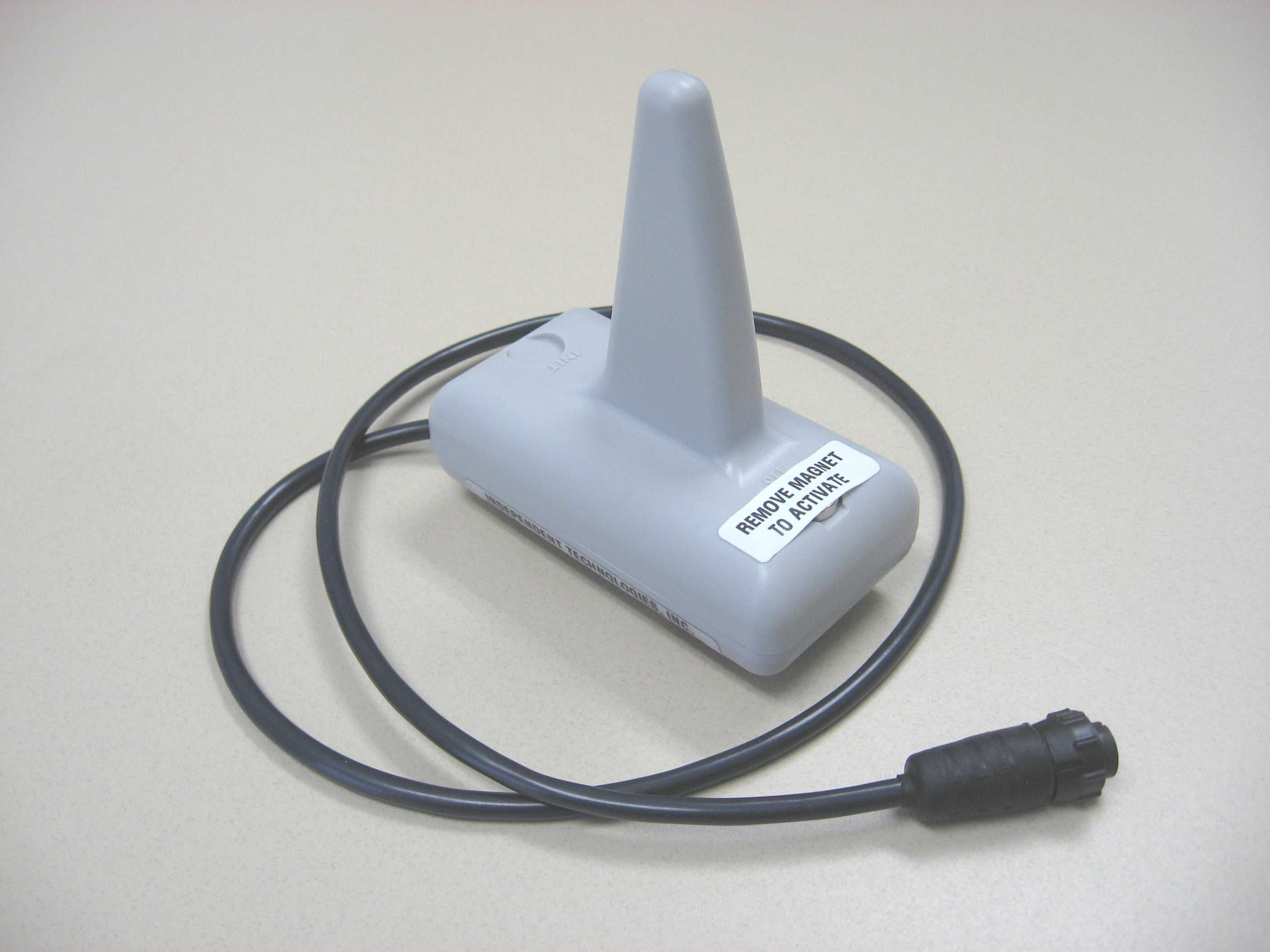
RWBMT9100TNK
Oct 17, 2007Fuel Tank Level Transmitter
Equipment Class
DTS - Digital Transmission System
RWB-MT9100R
Aug 30, 2006ESROC RMS Repeater
Equipment Class
DTS - Digital Transmission System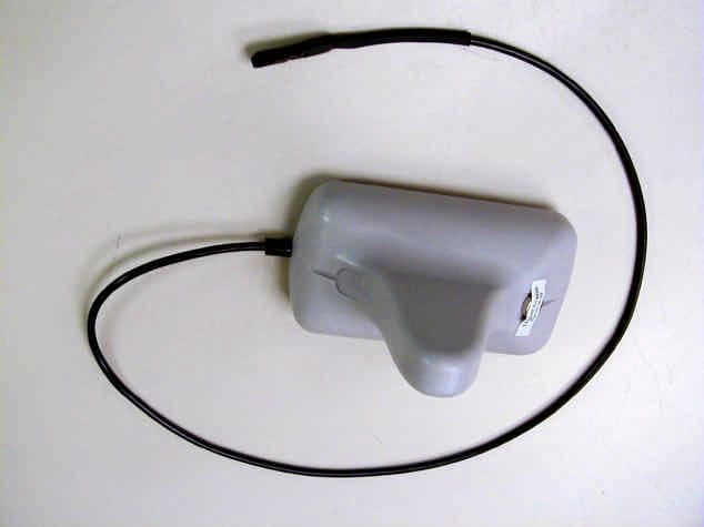
RWB-MT9100T
Mar 28, 2004WESROC RMS Transmitter MT-9100T
Equipment Class
DXX - Part 15 Low Power Communication Device Transmitter