RWZ-F8GSM Tri-band Digital Mobile Phone
AMOI Electronics Co., Ltd.
Click to zoom
Application Details
- Equipment Class
- PCE - PCS Licensed Transmitter held to ear
- Date of Grant
- May 08, 2005
- Application Purpose
- Original Equipment
- Date of Application
- May 08, 2005
- Equipment Note
- GSM Tri-band Digital Mobile Phone
- Frequency Range
- 1850.20000000 - 1909.80000000
- Company
- AMOI Electronics Co., Ltd.
- Country
- China
Documents & Files
Document Text
Text extracted from the exhibit documents filed with the FCC. Open a document above to read the original.
Users Manual
-1- Thank you very much for choosing AMOI F8, the fashionable and elegant camera phone, especially for youngster. F8 is a perfect integration of unparalleled contemporary design and consummate precise craftsmanship, bringing you easy communication, funny entertainment, as well as highlighting your tastes. Key features: GSM World Tr-iband Unlocked Compatible with Most Standard GSM Networks 65K Colors CSTN Main and External Displays GPRS Class 10, WAP 2.0 AMOI Smart Dial JAVA Enabled: J2ME SMS (Short Messaging Service) MMS (Multimedia Messaging Service) Downloadable 40-Polyphonic Ring Tones Built-in 300K pixels CMOS Video Camera Built-in Amusing Games Tool Kit (PC Sync, Alarm Clock, Calculator, Voice Memo, Unit Conversion, World Time) -2- Specifications: GSM/GPRS: 900 /1800 /1900 MHz Screen: Internal: 65k colors CSTN display (128 x 128 pixels) External: 65k colors CSTN display ( 96 x 64 pixels) Size: 80 x 42 x 21 mm; 3.15" x 1.65" x 0.83" Weight: 69 g; 2.43 oz Battery Capacity: 720 mAh Standby Time: 60-100 hrs Talk Time: 2-3 hrs Voice Encoding: FR / EFR / HR The manufacturer may, at any time and without notice, make changes or improvements to the products offered, but provide necessary corrigendum with this manual or release new version of this manual for the following lot. The Amoi logo and trademark are the property of the manufacturer. Oct. 2004 -3- Intellectual Property All Intellectual Property, as defined below, owned by or which is otherwise the property of AMOI or its respective suppliers relating to the AMOI mobile phones, including but not limited to, accessories, parts, or software relating thereto (the “Phone System”), is proprietary to AMOI and protected under federal laws, state laws, and international treaty provisions. Intellectual Property includes, but is not limited to, inventions (patentable or unpatentable), patents, trade secrets, copyrights, software, computer programs, and related documentation and other works of authorship. You could not infringe on it, otherwise you may violate the rights secured by the Intellectual Property. Moreover, you must agree that you will not (and will not attempt to) modify, prepare derivative works, recompile, disassemble, or attempt to create source code from the software. No title or ownership in the Intellectual Property is transferred to you. All applicable rights of the Intellectual Property shall remain with AMOI and its suppliers. -4- TABLE OF CONTENTS Safety precautions.................................................8 Unpacking.........................................................10 Yo u r P h o n e......................................................11 Phone Layout.......................................................11 Keys Description.................................................13 Display...............................................................14 Getting Started....................................................16 Installing a SIM Card.............................................16 Charging a Battery.................................................18 Switching the Phone On/Off......................................20 Your Phones Mode.................................................21 Call Function......................................................22 Making Calls.........................................................23 Receiving/ Rejecting Calls..........................................24 Volume Adjusting................................................24 Missed Calls..................................................25 Call Menu..........................................................25 Entering Text......................................................28 Changing Text Input Mode........................................28 English Mode.................................................30 BoPoMoFo Mode...................................................31 Abc Mode...........................................................31 Numeric/123 Mode.................................................32 Insert Symbol......................................................32 Insert Template......................................................33 Insert Phone Num...................................................33 -5- Using User’s Dictionary...........................................32 Phonebook...........................................................34 Storing a Phone Number in PB....................................34 PB Menu.............................................................37 Using Menus.........................................................40 Select functions of options.........................................40 List of Menu Function..............................................41 Messages..............................................................47 SMS....................................................................47 MMS..................................................................51 Voice Mail.........................................................54 Broadcast............................................................55 Memory............................................................55 Settings............................................................56 Data Service..........................................................58 Browser...............................................................58 PC Sync..............................................................59 JAVA..................................................................59 Settings...............................................................62 Personality............................................................64 Music Select.........................................................64 Alert Type............................................................64 Ring Volume......................................................64 Standby Interface....................................................................64 Power On/ Of…
Text truncated - open the document above for the full version.
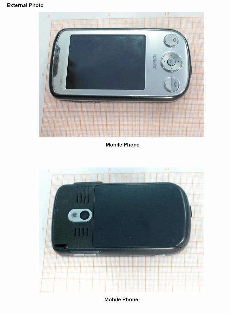
External Photos
Page 1 CONSTRUCTION PHOTOS OF EUT Page 2
ID Label/Location Info
FCC ID Label Location (FCC ID: RWZ-F8)
ID Label/Location Info
GSM Tri-band Digital Mobile Phone F8 AMOI FCC ID : RWZ-F8 Made in China
Internal Photos
Page 3 Page 4 Page 5 Page 6 Page 7 Page 8 Page 9 Page 10
Operational Description
1 General Technical Description Model: F8 Date: 2005-2-21 Band: EGSM900, DCS1800, PCS 1900 2 1. Scope This document is shown and provided the more detail information about the platform used in. The basic description for the Baseband and RF section are also included. 2. Detail Block Diagram 3. RF Front End RF Front architecture is based on AGERE’s Carbon highly integrated solution and comprise mainly chips: 3.1 SI4206BM Transceiver with Direct Conversion The SI4206BM supports EGSM900, DCS1800, and PCS 1900 application. The Aero I+ transceiver is a complete RF front end for multi-band GSM and GPRS wireless communications. The transmit section interfaces between the baseband processor and the power amplifier. The receive section interfaces between the RF band-select SAW filters and the baseband processor. All sensitive components, such as RF/IF VCOs, loop filters, and tuning inductors, are completely integrated into a single compact package. The Aero I+ includes a digitally-controlled crystal oscillator (DCXO) function and completely integrates the reference oscillator and varactor. 3.2 CX77312 Power Amplifier The PAM consists of separate GSM850/900 PA, DCS 1800/ PCS 1900 PA blocks, impedance- matching circuitry for 50ohm input and output impedance, and a Power Amplifier Control(PAC) block with an internal current-sense resistor .The custom CMOS integrated circuit provides the internal PAC function and interface circuitry. Fabricated 3 onto a single Gallium Arsenide (GaAs) die,one Heterojunction Bipolar Transistor(HBT) PA block supports the GSM850/900 bands and the other supports the DCS1800 and PCS1900 bands.Both PA block share common power supply pins to distribute current.The GaAs die, the Silicon(Si) die, and the passive components are mounted on a multi-layer laminate substrate.The assembly is encapsulated with plastic overmold. 4. Baseband Baseband architecture is based on AGERE’s Carbon highly integrated solution and comprise mainly three chips: 4.1 TR09WQTFC15IN2B-DB Digital Baseband Processor Trident is a platform designed for wireless terminals.It includes the DSP16000 core, ARM7TDMI micro-controller core,and a standard set of peripherals for the DSP and ARM. DSP peripherals: timer,one bit input/output unit(BIO),JTAG, external memory interface(EMI),and hardware development system(HDS). ARM peripherals: external memory interface(EMI),programmable interrupt controller(PIC),reset/power/clock unit, DMA controller, test interface controller(TIC),peripheral bridge, programmable peripheral interface(PPI),synchronous serial interface(SSI), two asynchronous communications controllers(ACCs),one with IrDA, timer ,analog-to-digital converter(A/D),real-timer clock(RTC),two smartcards, and keyboard interface. 4.2 M-G-CSP2200B1-YV10-DB Sceptre-TC Analog Baseband and Power Management IC) Sceptre-TC Analog Baseband and Power Management IC has two major logical components (subsystems): power management (PSC) and conversion signal processing (CSP) The device contains the following functions: _ Power management for RF, BB, and ancillary devices within the GSM/GPRS handset _ Battery-charge management _ Reset control _ SIM card voltage-level shifting The CSP component is responsible for the following: _ Intraframe event scheduling _ Voice band processing, including voice band ADC and DAC _ Analog baseband processing, including baseband ADC and DAC _ Providing RF interface for Trident digital baseband device _ Transmit power control 4 _ Automatic frequency control _ A5 ciphering _ Low-power sleep mode and wake-up control As shown in Figure 4, CSP2200B1 has the following major physical components: _ Timing and control unit (TCU) _ RF serial interface (TSIO) _ Low-power sleep mode controller _ Automatic frequency control DAC _ Baseband transmitter _ Baseband receiver _ Voice band input _ Voice band output _ A5 ciphering hardware support _ Power management
RF Exposure Info
APPENDIX A: TEST CONFIGURATIONS AND TEST DATA A1: TEST CONFIGURATION Body Worn Position The bottom of the EUT to the flat phantom distance 15 mm Left Head Cheek Position Left Head Tilt Position Right Head Cheek Position Right Head Tilt Position EUT Photo Liquid Level Photo Tissue 1900MHz D=150mm A-1 Date/Time: 2005/4/20 09:35:21 Test Laboratory: Advance Data Technology F8 Left Head PCS1900 DUT: GSM Tri-band Digital Mobile Phone ; Type: F8 ; Test Frequency: 1850.2 MHz Communication System: PCS 1900 ; Frequency: 1850.2 MHz ; Duty Cycle: 1:8.3 Phantom: SAM 12 Medium parameters used: f = 1850.2 MHz; σ = 1.33 mho/m; ε r = 38.7; ρ = 1000 kg/m 3 ; Liquid level: 150mm Phantom section: Left Section ; DUT test position : Cheek ; Modulation type: GMSK Antenna type : External Antenna ; Air temp. : 22.0 degrees ; Liquid temp. : 21.0 degrees DASY4 Configuration: - Probe: ET3DV6 - SN1753; ConvF(5.17, 5.17, 5.17) ; Calibrated: 2004/8/26 - Sensor-Surface: 4mm (Mechanical Surface Detection) - Electronics: DAE3 Sn579; Calibrated: 2005/3/23 - Phantom: SAM 12; Type: SAM V4.0; Serial: TP 1202 - Measurement SW: DASY4, V4.5 Build 19; Postprocessing SW: SEMCAD, V1.8 Build 146 Touch position - Low Channel/Area Scan (7x13x1): Measurement grid: dx=15mm, dy=15mm Maximum value of SAR (measured) = 0.554 mW/g Touch position - Low Channel/Zoom Scan (7x7x7) (7x7x7)/Cube 0: Measurement grid: dx=5mm, dy=5mm, dz=5mm Reference Value = 5.70 V/m; Peak SAR (extrapolated) = 0.845 W/kg SAR(1 g) = 0.561 mW/g; SAR(10 g) = 0.320 mW/g Maximum value of SAR (measured) = 0.614 mW/g A-2 Date/Time: 2005/4/20 10:02:39 Test Laboratory: Advance Data Technology F8 Left Head PCS1900 DUT: GSM Tri-band Digital Mobile Phone ; Type: F8 ; Test Frequency: 1880 MHz Communication System: PCS 1900 ; Frequency: 1880 MHz ; Duty Cycle: 1:8.3 Phantom: SAM 12 Medium parameters used: f = 1880 MHz; σ = 1.38 mho/m; ε r = 38.5; ρ = 1000 kg/m 3 ; Liquid level: 150mm Phantom section: Left Section ; DUT test position : Cheek ; Modulation type: GMSK Antenna type : External Antenna ; Air temp. : 22.0 degrees ; Liquid temp. : 21.0 degrees DASY4 Configuration: - Probe: ET3DV6 - SN1753; ConvF(5.17, 5.17, 5.17) ; Calibrated: 2004/8/26 - Sensor-Surface: 4mm (Mechanical Surface Detection) - Electronics: DAE3 Sn579; Calibrated: 2005/3/23 - Phantom: SAM 12; Type: SAM V4.0; Serial: TP 1202 - Measurement SW: DASY4, V4.5 Build 19; Postprocessing SW: SEMCAD, V1.8 Build 146 Touch position - Middle Channel/Area Scan (7x13x1): Measurement grid: dx=15mm, dy=15mm Maximum value of SAR (measured) = 0.687 mW/g Touch position - Middle Channel/Zoom Scan (7x7x7) (7x7x7)/Cube 0: Measurement grid: dx=5mm, dy=5mm, dz=5mm Reference Value = 5.83 V/m; Peak SAR (extrapolated) = 1.06 W/kg SAR(1 g) = 0.698 mW/g; SAR(10 g) = 0.397 mW/g Maximum value of SAR (measured) = 0.766 mW/g A-3 Date/Time: 2005/4/20 10:26:52 Test Laboratory: Advance Data Technology F8 Left Head PCS1900 DUT: GSM Tri-band Digital Mobile Phone ; Type: F8 ; Test Frequency: 1909.8 MHz Communication System: PCS 1900 ; Frequency: 1909.8 MHz ; Duty Cycle: 1:8.3 Phantom: SAM 12 Medium parameters used: f = 1909.8 MHz; σ = 1.42 mho/m; ε r = 38.6; ρ = 1000 kg/m 3 ; Liquid level: 150mm Phantom section: Left Section ; DUT test position : Cheek ; Modulation type: GMSK Antenna type : External Antenna ; Air temp. : 22.0 degrees ; Liquid temp. : 21.0 degrees DASY4 Configuration: - Probe: ET3DV6 - SN1753; ConvF(5.17, 5.17, 5.17) ; Calibrated: 2004/8/26 - Sensor-Surface: 4mm (Mechanical Surface Detection) - Electronics: DAE3 Sn579; Calibrated: 2005/3/23 - Phantom: SAM 12; Type: SAM V4.0; Serial: TP 1202 - Measurement SW: DASY4, V4.5 Build 19; Postprocessing SW: SEMCAD, V1.8 Build 146 Touch position - High Channel/Area Scan (7x13x1): Measurement grid: dx=15mm, dy=15mm Maximum value of SAR (measured) = 0.983 mW/g Touch position - High Channel/Zoom Scan (7x7x7) (7x7x7)/Cube 0: Measurement grid: dx=5mm, dy=5mm, dz=5mm Reference Value = 6.59 V/m; Peak SAR (extrapolated) = 1.48 W/kg SAR(1 g) = 1 mW/g; SAR(10 g) = 0.572 mW/g Maximum value of SAR (measured) = 1.10 mW/g A-4 A-5 Date/Time: 2005/4/20 10:51:14 Test Laboratory: Advance Data Technology F8 Left Head PCS1900 DUT: GSM Tri-band Digital Mobile Phone ; Type: F8 ; Test Channel Frequency: 1850.2 MHz Communication System: PCS 1900 ; Frequency: 1850.2 MHz; Duty Cycle: 1:8.3 Medium: HSL1900 Medium parameters used: f = 1850.2 MHz; σ = 1.33 mho/m; ε r = 38.7; ρ = 1000 kg/m 3 ; Liquid level: 150 mm Phantom section: Left Section ; DUT test position : Tilt ; Modulation type: GMSK Antenna type : External Antenna ; Air temp. : 22.0 degrees ; Liquid temp. : 21.0 degrees DASY4 Configuration: - Probe: ET3DV6 - SN1753 ; ConvF(5.17, 5.17, 5.17) ; Calibrated: 2004/8/26 - Sensor-Surface: 4mm (Mechanical Surface Detection) - Electronics: DAE3 Sn579; Calibrated: 2005/3/23 - Phantom: SAM 12; Type: SAM V4.0; Serial: TP 1202 - Measurement SW: DASY4, V4.5 Build 19; Postprocessing SW: SEMCAD, V1.8 Build 146 Tilt position - Low Channel/Area Scan (7x13x1): Measurement grid: dx=15mm, dy=15mm Maximum value of SAR (measured) = 0.368 mW/g Tilt position - Low Channel/Zoom Scan (7x7x7) (7x7x7)/Cube 0: Measurement grid: dx=5mm, dy=5mm, dz=5mm Reference Value = 16.8 V/m; Peak SAR (extrapolated) = 0.534 W/kg SAR(1 g) = 0.360 mW/g; SAR(10 g) = 0.224 mW/g Maximum value of SAR (measured) = 0.389 mW/g A-6 Date/Time: 2005/4/20 11:14:03 Test Laboratory: Advance Data Technology F8 Left Head PCS1900 DUT: GSM Tri-band Digital Mobile Phone ; Type: F8 ; Test Channel Frequency: 1880 MHz Communication System: PCS 1900 ; Frequency: 1880 MHz; Duty Cycle: 1:8.3 Medium: HSL1900 Medium parameters used: f = 1880 MHz; σ = 1.38 mho/m; ε r = 38.5; ρ = 1000 kg/m 3 ; Liquid level: 150 mm Phantom section: Left Section ; DUT test position : Tilt ; Modulation type: GMSK Antenna type : External Antenna ; Air temp. : 22.0 degrees ; Liquid temp. : 21.0 degrees DASY4 Configuration: - Probe: ET3DV6 - SN1753 ; ConvF(5.17, 5.17, 5.17) ; Calibrated: 2004/8/26 - Sensor-S…
Text truncated - open the document above for the full version.
RF Exposure Info
B - 1 APPENDIX B: ADT SAR MEASUREMENT SYSTEM C - 1 APPENDIX C: PHOTOGRAPHS OF SYSTEM VALIDATION
RF Exposure Info
D - 1 APPENDIX D: SYSTEM CERTIFICATE & CALIBRATION D1: SAM PHANTOM D - 2 D2: DOSIMETRIC E-FIELD PROBE SN: 1753 D3: DAE SN: 579 D4: 1900 MHz SYSTEM VALIDATION DIPOLE SN: 5d036
RF Exposure Info
FCC ID: RWZ-F8 Report No.: SA940407L071Report Format Version 2.0.1 SAR TEST REPORT REPORT NO.: SA940407L07 MODEL NO.: F8 RECEIVED: Apr. 11, 2005 TESTED: Apr. 20, 2005 ISSUED: Apr. 29, 2005 APPLICANT: Amoi Electronics Co., Ltd ADDRESS: No. 45, Tiyu Road, Xiamen, Fujian, China ISSUED BY: Advance Data Technology Corporation LAB ADDRESS: No. 47, 14th Ling, Chia Pau Tsuen, Lin Kou Hsiang 244, Taipei Hsien, Taiwan, R.O.C. TEST LOCATION: No. 19, Hwa Ya 2 nd Rd., Wen Hwa Tsuen, Kwei Shan Hsiang, Taoyuan Hsien 333, Taiwan, R.O.C. This test report consists of 35 pages in total except Appendix. It may be duplicated completely for legal use with the approval of the applicant. It should not be reproduced except in full, without the written approval of our laboratory. The client should not use it to claim product endorsement by CNLA, A2LA or any government agencies. The test results in the report only apply to the tested sample. 0528 ILAC MRA NO. 2177-01 FCC ID: RWZ-F8 Report No.: SA940407L072Report Format Version 2.0.1 Table of Contents 1.CERTIFICATION .........................................................................................................3 2.GENERAL INFORMATION..........................................................................................4 2.1 GENERAL DESCRIPTION OF EUT............................................................................4 2.2 GENERAL DESCRIPTION OF APPLIED STANDARDS .............................................5 2.3 GENERAL INOFRMATION OF THE SAR SYSTEM ...................................................5 2.4 GENERAL DESCRIPTION OF THE SPATIAL PEAK SAR EVALUATION ..................9 3.DESCRIPTION OF TEST POSITION AND CONFIGURATIONS ..............................12 3.1 TOUCH/CHEEK TEST POSITION ............................................................................13 3.2 TILT TEST POSITION ...............................................................................................14 3.3 BODY-WORN CONFIGURATION .............................................................................14 4.DESCRIPTION OF TEST MODE ..............................................................................15 5.DESCRIPTION OF SUPPORT UNITS ......................................................................16 6.TEST RESULTS ........................................................................................................17 5.1 TEST PROCEDURES ...............................................................................................17 5.2 MEASURED SAR RESULTS ....................................................................................18 5.3 SAR LIMITS...............................................................................................................21 5.4 RECIPES FOR TISSUE SIMULATING LIQUIDS ......................................................21 5.5 TEST EQUIPMENT FOR TISSUE PROPERTY ........................................................24 7.SYSTEM VALIDATION ..............................................................................................25 6.1 TEST EQUIPMENT ...................................................................................................25 6.2 TEST PROCEDURE .................................................................................................25 6.3 VALIDATION RESULTS ............................................................................................27 6.4 SYSTEM VALIDATION UNCERTAINTIES ................................................................28 8.MEASUREMENT SAR PROCEDURE UNCERTAINTIES.........................................29 7.1 PROBE CALIBRATION UNCERTAINTY ..................................................................29 7.2 ISOTROPY UNCERTAINTY .....................................................................................29 7.3 BOUNDARY EFFECT UNCERTAINTY.....................................................................30 7.4 PROBE LINEARITY UNCERTAINTY........................................................................30 7.5 READOUT ELECTRONICS UNCERTAINTY ............................................................31 7.6 RESPONSE TIME UNCERTAINTY ..........................................................................31 7.7 INTEGRATION TIME UNCERTAINTY ......................................................................32 7.8 PROBE POSITIONER MECHANICAL TOLERANCE ...............................................32 7.9 PROBE POSITIONING .............................................................................................33 7.10 PHANTOM UNCERTAINTY ......................................................................................33 7.11 DASY4 UNCERTAINTY BUDGET ............................................................................34 9.INFORMATION ON THE TESTING LABORATORIES ..............................................35 APPENDIX A: TEST CONFIGURATIONS AND TEST DATA APPENDIX B: ADT SAR MEASUREMENT SYSTEM APPENDIX C: PHOTOGRAPHS OF SYSTEM VALIDATION APPENDIX D: SYSTEM CERTIFICATE & CALIBRATION FCC ID: RWZ-F8 Report No.: SA940407L073Report Format Version 2.0.1 1. CERTIFICATION PRODUCT : GSM Tri-band Digital Mobile Phone MODEL NO. : F8 BRAND NAME : AMOI APPLICANT : Amoi Electronics Co., Ltd TEST DATE: Apr. 20, 2005 TEST SAMPLE: MASS-PRODUCTION STANDARDS : FCC Part 2 (Section 2.1093), FCC OET Bulletin 65, Supplement C (01-01), RSS-102 The above equipment have been tested by Advance Data Technology Corporation, and found compliance with the requirement of the above standards. The test record, data evaluation & Equipment Under Test (EUT) configurations represented herein are true and accurate accounts of the measurements of the sample’s EMC characteristics under the conditions specified in this report. PREPARED BY:, DATE:Apr. 29, 2005 ( Andrea Hsia ) TECHNICAL ACCEPTANCE :, DATE:Apr. 29, 2005 Responsible for RF ( Ansen Lei ) APPROVED BY:, DATE:Apr. 29, 2005 (Cody Chang, Deputy Manger ) FCC ID: RWZ-F8 Report No.: SA940407L…
Text truncated - open the document above for the full version.
Test Report
FCC ID: RWZ-F8 Report No.: RF940407L071Report Format Version 2.0.1 FCC TEST REPORT (Part 24) REPORT NO.: RF940407L07 MODEL NO.: F8 RECEIVED: Apr. 11, 2005 TESTED: Apr. 15 ~ Apr. 28, 2005 ISSUED: May 02, 2005 APPLICANT: Amoi Electronics Co., Ltd ADDRESS: No. 45, Tiyu Road, Xiamen, Fujian, China ISSUED BY: Advance Data Technology Corporation LAB ADDRESS: No. 47, 14th Ling, Chia Pau Tsuen, Lin Kou Hsiang 244, Taipei Hsien, Taiwan, R.O.C. TEST LOCATION: No. 19, Hwa Ya 2 nd Rd., Wen Hwa Tsuen, Kwei Shan Hsiang, Taoyuan Hsien 333, Taiwan, R.O.C. This test report consists of 73 pages in total. It may be duplicated completely for legal use with the approval of the applicant. It should not be reproduced except in full, without the written approval of our laboratory. The client should not use it to claim product endorsement by CNLA , A2LA or any government agencies. The test results in the report only apply to the tested sample. NO. 2177-01 0528 ILAC MRA FCC ID: RWZ-F8 Report No.: RF940407L072Report Format Version 2.0.1 Table of Contents 1CERTIFICATION .......................................................................................................4 2SUMMARY OF TEST RESULTS ...............................................................................5 2.1MEASUREMENT UNCERTAINTY.............................................................................6 3GENERAL INFORMATION........................................................................................7 3.1GENERAL DESCRIPTION OF EUT ..........................................................................7 3.2DESCRIPTION OF TEST MODES ............................................................................8 3.3GENERAL DESCRIPTION OF APPLIED STANDARDS ...........................................8 3.4DESCRIPTION OF SUPPORT UNITS ......................................................................9 4TEST TYPES AND RESULTS .................................................................................10 4.1MODULATION CHARACTERISTICS ......................................................................10 4.1.1DESCRIPTION OF MODULATION TECHNIQUE ...................................................10 4.1.2THE ACTIVE TIME SLOT 8 MODULATED FRAME PLOT...................................... 11 4.2OUTPUT POWER MEASUREMENT ......................................................................13 4.2.1LIMITS OF OUTPUT POWER MEASUREMENT ....................................................13 4.2.2TEST INSTRUMENTS.............................................................................................14 4.2.3TEST PROCEDURES .............................................................................................15 4.2.4TEST SETUP...........................................................................................................16 4.2.5EUT OPERATING CONDITIONS ............................................................................17 4.2.6TEST RESULTS ......................................................................................................18 4.3FREQUENCY STABILITY MEASUREMENT...........................................................20 4.3.1LIMITS OF FREQUENCY STABILIITY MEASUREMENT .......................................20 4.3.2TEST INSTRUMENTS.............................................................................................20 4.3.3TEST PROCEDURE................................................................................................21 4.3.4TEST SETUP...........................................................................................................21 4.3.5TEST RESULTS ......................................................................................................22 4.4OCCUPIED BANDWIDTH MEASUREMENT ..........................................................24 4.4.1LIMITS OF OCCUPIED BANDWIDTH MEASUREMENT .......................................24 4.4.2TEST INSTRUMENTS.............................................................................................24 4.4.3TEST SETUP...........................................................................................................24 4.4.4TEST PROCEDURES .............................................................................................25 4.4.5EUT OPERATING CONDITION ..............................................................................25 4.4.6TEST RESULTS ......................................................................................................25 4.5BAND EDGE MEASUREMENT...............................................................................32 4.5.1LIMITS OF BAND EDGE MEASUREMENT ............................................................32 4.5.2TEST INSTRUMENTS.............................................................................................32 FCC ID: RWZ-F8 Report No.: RF940407L073Report Format Version 2.0.1 4.5.3TEST SETUP...........................................................................................................32 4.5.4TEST PROCEDURES .............................................................................................33 4.5.5EUT OPERATING CONDITION ..............................................................................33 4.5.6TEST RESULTS ......................................................................................................34 4.6CONDUCTED SPURIOUS EMISSIONS .................................................................36 4.6.1LIMITS OF CONDUCTED SPURIOUS EMISSIONS MEASUREMENT .................36 4.6.2TEST INSTRUMENTS.............................................................................................36 4.6.3TEST PROCEDURE................................................................................................37 4.6.4TEST SETUP...........................................................................................................37 4.6.5EUT OPERATING CONDITIONS ...................................................…
Text truncated - open the document above for the full version.
Test Setup Photos
FCC ID: RWZ-F8 Report No.: RF940407L0772Report Format Version 2.0.1 5 PHOTOGRAPHS OF THE TEST CONFIGURATION RADIATED EMISSION TEST (EUT without the adapter) FCC ID: RWZ-F8 Report No.: RF940407L0773Report Format Version 2.0.1 RADIATED EMISSION TEST (EUT with the adapter)
Contact Information
Applicant
William Ding(Manager)
Technical Contact
Advance Data Technology CorporationCody Chang
[email protected]886-3-3183232
No. 19, Hwa Ya 2nd Rd., Kwei Shan Hsiang · Taoyuan Hsien · Taiwan
Non-Technical Contact
Advance Data Technology CorporationStephanie Hung
[email protected]886-3-3183232
Test Firm
Bureau Veritas CPS (H.K.) Ltd. Taoyuan BranchRichard Chen
Technical Specifications
| # | Rule Parts | Frequency Range | Power Output | Emission | Tolerance |
|---|---|---|---|---|---|
| 1 | 24E | 1.85 GHz - 1.91 GHz | 940.00 mW | 300KGXW | 0.1000000000 ppm |
Other Applications from AMOI Electronics Co., Ltd.
RWZ-N810
Nov 11, 2007PCS1900 (Mobile Phone)
Equipment Class
PCF - PCS Licensed Transmitter held to face
RWZ-SMT5700WOC
Sep 09, 2007GSM850 AND PCS1900 (Mobile Phone)
Equipment Class
DSS - Part 15 Spread Spectrum Transmitter
RWZV870
Apr 24, 2007CDMA 1X EVDO/GSM Digital Mobile Phone
Equipment Class
PCE - PCS Licensed Transmitter held to ear
RWZ-6711
Mar 15, 2007GSM850 AND PCS1900 (Mobile Phone)
Equipment Class
PCE - PCS Licensed Transmitter held to ear
RWZ-A320A
Dec 22, 2005Tri Band GSM Mobile Phone
Equipment Class
PCE - PCS Licensed Transmitter held to ear