RWZ-N810PCS1900 (Mobile Phone)
AMOI Electronics Co., Ltd.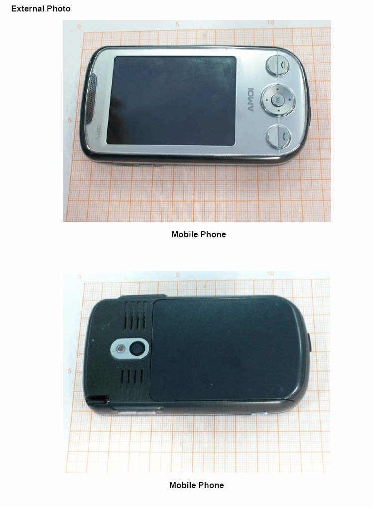
Click to zoom
Application Details
- Equipment Class
- PCF - PCS Licensed Transmitter held to face
- Date of Grant
- Nov 11, 2007
- Application Purpose
- Original Equipment
- Date of Application
- Nov 11, 2007
- Equipment Note
- PCS1900 (Mobile Phone)
- Frequency Range
- 1850.20000000 - 1909.80000000
- Company
- AMOI Electronics Co., Ltd.
- Country
- China
Documents & Files
Document Text
Text extracted from the exhibit documents filed with the FCC. Open a document above to read the original.
Users Manual
N810 User Manual Touching Your Future Welcome to the user guide for the N810 mobile phone. With a whole suite of powerful business functions and entertainment programs, the N810 provides a fresh and exciting level of enjoyment. By using the GPS (Global Positioning System), the N810 will provide you a variety of the best routes and real-time voice service according to your different needs. You can easily locate your current position and the correct direction. The N810 can take photos or record video clips with the built-in 2 million pixel CMOS camera, which lets you memories every wonderful moment. Connect to the Internet with Internet Explorer; synchronize your phone and PC with ActiveSync. Wherever you go, whatever you do, keep the N810 close and never skip a beat. Special features Supports GPS (page 88 ) Built-in 2 mega pixel CMOS camera (page 80) Built-in ActiveSync to synchronize with PC (page 65) Touch Screen and Manual Input Identification (page 25) Supports Windows Mobile 6.0 Supports Micro-SD card (page 87) Internet sharing (page 75 ) Supports Outlook email (page 48 ) 65 K , 2.8 inches Screen Windows Media (page 77 ) Declaration Copyright: 2007 Amoi Electronic Co. Ltd reserves all rights. The content of this guide is protected by Copyright Law. It is forbidden to copy, distribute, publish or cite the content of this user guide, in whatever form, without the authorisation of Amoi Electronic Co. Ltd. JAVA is the registered trademark of Sun Microsystems, Inc. “ ” and “ “are registered trade marks and belong to Amoi. They are protected by law. The other products or company names referred to in this guide are registered trademarks, trademarks, or registered names belonging to their owners. Amoi has carefully and closely reviewed the content of this user guide. Nevertheless, it is possible that there are mistakes and omissions. Amoi reserves the right to update and improve any products described in this guide, as well as the content of this guide. Amendments will be made without prior notification. The is the user guide for the Amoi mobile phone only and does not include an introduction to this product’s software and hardware configuration. The product and spare parts vary according to region. For more details, please contact an Amoi customer service centre. Some functions referred to in this guide also need the support of a network operator or service provider. If you are unable to confirm whether you will be able to use certain functions or services with this phone, please consult your network operator or service provider. The phone may include some commodities, technology or software that is controlled by export law, Chinese regulations and regulations governed by other countries or areas. In order to ensure your safety, please read the “Safety Notice” and “Safety Precaution”. Typographic conventions used in this user guide include: <>: shows function key; ““: shows important information on the phone interface; [ ]: shows the phone menus. I Content Safety notice ............................................... VII 1.Getting to know your phone......................1 Your phone....................................................... 1 Front view of your phone.............................. 1 Side view of your phone ............................... 1 Rear view of your phone .............................. 2 The Today Screen ............................................ 2 Status Icon ....................................................... 3 2.Getting Started............................................6 Installing SIM card and battery......................... 6 Installing Micro SD card ................................... 7 Battery charging............................................... 8 Battery power display....................................... 9 Power on/ off .................................................... 9 Switching the phone on ................................ 9 Switching the phone off .............................. 10 Turning the phone function on/off................... 11 Turning on the phone function.................... 11 Turning off the phone function.................... 11 Using shortcut keys........................................ 12 Using Stylus ................................................... 12 Instruction for the first used............................ 13 Touch screen and Calibration..................... 13 Align screen ............................................... 13 Text Size..................................................... 13 Reminder........................................................14 Start ................................................................14 Programs ....................................................14 Device locked .................................................15 Device Lock ................................................15 Locking the phone ......................................15 Locking SIM Card .......................................15 3.Call Functions ...........................................17 Entering the phone screen .............................17 Enter PIN code ...........................................17 Making a call ..................................................18 To make a call from the Pone Screen .........18 To make a call from Contacts......................18 To make a call from Call History .................18 To make a call from Speed Dial ..................18 Creating a speed dial number from Contacts ...................................................................19 Editing or canceling a speed dial number ...19 To make an emergency call ........................20 To make an international call ......................20 Caller ID......................................................20 Checking Voice Mail ...................................20 To adjust the volume...................................20 Answering or rejecting a call...........................21 Answering or rejecting an incoming call......21…
Text truncated - open the document above for the full version.
Attestation Statements
Attestation Letter 2007-10-25 TO WHOM IT MAY CONCERN FCC ID Number Product Title / Model RWZ-N810 N810 For the product stated above, we confirm the Class of GPRS is Class l0. Two time slot were used for GPRS uplink and four time slots were used for GPRS downlink If you have any questions, please feel free to contact me at the address shown below. Sincerely, dehai di Product Test Manager AMOI Electronics CO.,LTD Add:102 Xiaguang Road,Haicang district,Xiamen City,Fujian Province 361022,P.R.China Tel:86-592-6516777-3316 Fax:86-592-6516007 Mobile:86-13110931077 Email: [email protected]
Attestation Statements
Attestation Letter 2007-10-25 TO WHOM IT MAY CONCERN FCC ID Number Product Title / Model RWZ-N810 N810 For the product stated above, we confirm the Class of GPRS is Class l0. Two time slot were used for GPRS uplink and four time slots were used for GPRS downlink If you have any questions, please feel free to contact me at the address shown below. Sincerely, dehai di Product Test Manager AMOI Electronics CO.,LTD Add:102 Xiaguang Road,Haicang district,Xiamen City,Fujian Province 361022,P.R.China Tel:86-592-6516777-3316 Fax:86-592-6516007 Mobile:86-13110931077 Email: [email protected]
Cover Letter(s)
Federal Communication Commission Equipment Authorization Division, Application Processing Branch 7435 Oakland Mills Road Columbia, MD 21048 2007-10-25 TO WHOM IT MAY CONCERN Pursuant to Paragraphs §0.457 and 0.459 of the Commission’s Rules (47 C.F.R.) and Section §552(b)(4) of the Freedom of Information Act, Amoi Electronics Co Ltd requests confidentiality for the following products: FCC ID Number Product Title / Model RWZ-N810 N810 For the product stated above, we request that the following information be held confidential: 1) Electrical Schematics of the Circuitry 2) Block Diagram 3) Parts List 4) Technical Description Required for section 2.1003(c) z Operational Description Other items submitted as part of the equipment authorization filing process are deemed confidential. The above exhibits contain Amoi Electornics Co LTD Information and Communication Mobile trade secrets and proprietary information that could be of benefit to our competitors regarding the design of our mobile handset. This material is not customarily available to general public and we request that it be withheld from public inspection. If you have any questions, please feel free to contact me at the address shown below. Sincerely, dehai di Product Test Manager AMOI Electronics CO.,LTD Add:102 Xiaguang Road,Haicang district,Xiamen City,Fujian Province 361022,P.R.China Tel:86-592-6516777-3316 Fax:86-592-6516007 Mobile:86-13110931077 Email: [email protected]
Cover Letter(s)
Federal Communication Commission Equipment Authorization Division, Application Processing Branch 7435 Oakland Mills Road Columbia, MD 21048 2007-10-25 TO WHOM IT MAY CONCERN Pursuant to Paragraphs §0.457 and 0.459 of the Commission’s Rules (47 C.F.R.) and Section §552(b)(4) of the Freedom of Information Act, Amoi Electronics Co Ltd requests confidentiality for the following products: FCC ID Number Product Title / Model RWZ-N810 N810 For the product stated above, we request that the following information be held confidential: 1) Electrical Schematics of the Circuitry 2) Block Diagram 3) Parts List 4) Technical Description Required for section 2.1003(c) z Operational Description Other items submitted as part of the equipment authorization filing process are deemed confidential. The above exhibits contain Amoi Electornics Co LTD Information and Communication Mobile trade secrets and proprietary information that could be of benefit to our competitors regarding the design of our mobile handset. This material is not customarily available to general public and we request that it be withheld from public inspection. If you have any questions, please feel free to contact me at the address shown below. Sincerely, dehai di Product Test Manager AMOI Electronics CO.,LTD Add:102 Xiaguang Road,Haicang district,Xiamen City,Fujian Province 361022,P.R.China Tel:86-592-6516777-3316 Fax:86-592-6516007 Mobile:86-13110931077 Email: [email protected]
RF Exposure Info
©Copyright. All rights reserved by TMC Beijing. SAR TEST REPORT No. 2007SAR00045 for Amoi Mobile Co., Ltd. Tri-band GSM Digital Mobile Phone N810 With Hardware Version: V1.0 Software Version: N810_V3.0.0_070930_BYD_CHS Issued Date: 2007-10-26 No. DAT-P-114/01-01 Note: The test results in this test report relate only to the devices specified in this report. This report shall not be reproduced except in full without the written approval of TMC Beijing. Test Laboratory: TMC Beijing, Telecommunication Metrology Center of Ministry of Information Industry No. 52, Huayuan Bei Road, Haidian District, Beijing, P. R. China 100083. Tel:+86(0)10-62303288-2105, Fax:+86(0)10-62304793 Email:[email protected]. www.emcite.com No. 2007SAR00045 Page 2 of 71 TABLE OF CONTENT 1 TEST LABORATORY .............................................................................................................................. 4 1.1 TESTING LOCATION...............................................................................................................................4 1.2 TESTING ENVIRONMENT........................................................................................................................ 4 1.3 PROJECT DATA....................................................................................................................................... 4 2 CLIENT INFORMATION........................................................................................................................ 4 2.1 APPLICANT INFORMATION..................................................................................................................... 4 2.2 MANUFACTURER INFORMATION............................................................................................................ 4 3 EQUIPMENT UNDER TEST (EUT) AND ANCILLARY EQUIPMENT (AE) .................................. 5 3.1 ABOUT EUT........................................................................................................................................... 5 3.2 INTERNAL IDENTIFICATION OF EUT USED DURING THE TEST................................................................ 5 3.3 INTERNAL IDENTIFICATION OF AE USED DURING THE TEST................................................................... 5 4 OPERATIONAL CONDITIONS DURING TEST ................................................................................. 6 4.1 SCHEMATIC TEST CONFIGURATION........................................................................................................ 6 4.2 SAR MEASUREMENT SET-UP................................................................................................................. 6 4.3 DASY4 E-FIELD PROBE SYSTEM............................................................................................................ 7 4.4 E-FIELD PROBE CALIBRATION............................................................................................................... 8 4.5 OTHER TEST EQUIPMENT....................................................................................................................... 8 4.6 EQUIVALENT TISSUES............................................................................................................................ 9 4.7 SYSTEM SPECIFICATIONS....................................................................................................................... 9 5 CHARACTERISTICS OF THE TEST..................................................................................................10 5.1 APPLICABLE LIMIT REGULATIONS....................................................................................................... 10 5.2 APPLICABLE MEASUREMENT STANDARDS.......................................................................................... 10 6 CONDUCTED OUTPUT POWER MEASUREMENT ........................................................................11 6.1 SUMMARY.............................................................................................................................................11 6.2 CONDUCTED POWER.............................................................................................................................11 7 TEST RESULTS .......................................................................................................................................11 7.1 DIELECTRIC PERFORMANCE.................................................................................................................11 7.2 SYSTEM VALIDATION........................................................................................................................... 12 7.3 SUMMARY OF MEASUREMENT RESULTS.............................................................................................. 12 7.4 CONCLUSION....................................................................................................................................... 13 8 MEASUREMENT UNCERTAINTY ..................................................................................................... 13 9 MAIN TEST INSTRUMENTS ............................................................................................................... 14 ANNEX A: MEASUREMENT PROCESS ........................................................................................... 15 ANNEX B: TEST LAYOUT ................................................................................................................... 16 ANNEX C: GRAPH RESULTS.............................................................................................................. 20 ANNEX D: SYSTEM VALIDATION RESULTS.................................................................................. 56 ANNEX E: PROBE CALIBRATION CERTIFICATE ..................................................................... 57 ANNEX F: DIPOLE CALIBRATION CERTIFICATE .................................................................... 66 No. 2007SAR00045 Page 4 of 71 1…
Text truncated - open the document above for the full version.
RF Exposure Info
No. 2007SAR00045 Page 36 of 71 1900 Right Cheek Low Date/Time: 2007-10-18 8:45:14 Electronics: DAE4 Sn777 Medium: Head 1900 MHz Medium parameters used (interpolated): f = 1850.2 MHz; σ = 1.36 mho/m; ε r = 40.9; ρ = 1000 kg/m 3 Ambient Temperature:23.3 o C Liqiud Temperature: 22.5 o C Communication System: GSM 1900MHz new Frequency: 1850.2 MHz Duty Cycle: 1:8.3 Probe: ET3DV6 - SN1736 ConvF(5.4, 5.4, 5.4) Cheek Low/Area Scan (61x91x1): Measurement grid: dx=10mm, dy=10mm Maximum value of SAR (interpolated) = 0.207 mW/g Cheek Low/Zoom Scan (7x7x7)/Cube 0: Measurement grid: dx=5mm, dy=5mm, dz=5mm Reference Value = 11.4 V/m; Power Drift = -0.116 dB Peak SAR (extrapolated) = 0.309 W/kg SAR(1 g) = 0.186 mW/g; SAR(10 g) = 0.110 mW/g Maximum value of SAR (measured) = 0.193 mW/g 0 dB = 0.193mW/g Fig. 17 1900 MHz CH512 No. 2007SAR00045 Page 37 of 71 Fig. 18 Z-Scan at power reference point (1900 MHz CH512) No. 2007SAR00045 Page 38 of 71 1900 Right Tilt High Date/Time: 2007-10-18 9:28:53 Electronics: DAE4 Sn777 Medium: Head 1900 MHz Medium parameters used: f = 1910 MHz; σ = 1.39 mho/m; ε r = 40.8; ρ = 1000 kg/m 3 Ambient Temperature:23.3 o C Liqiud Temperature: 22.5 o C Communication System: GSM 1900MHz new Frequency: 1909.8 MHz Duty Cycle: 1:8.3 Probe: ET3DV6 - SN1736 ConvF(5.4, 5.4, 5.4) Tilt High/Area Scan (61x91x1): Measurement grid: dx=10mm, dy=10mm Maximum value of SAR (interpolated) = 0.216 mW/g Tilt High/Zoom Scan (7x7x7)/Cube 0: Measurement grid: dx=5mm, dy=5mm, dz=5mm Reference Value = 12.3 V/m; Power Drift = -0.030 dB Peak SAR (extrapolated) = 0.305 W/kg SAR(1 g) = 0.192 mW/g; SAR(10 g) = 0.114 mW/g Maximum value of SAR (measured) = 0.203 mW/g 0 dB = 0.203mW/g Fig. 19 1900 MHz CH810 No. 2007SAR00045 Page 39 of 71 Fig. 20 Z-Scan at power reference point (1900 MHz CH810) No. 2007SAR00045 Page 40 of 71 1900 Right Tilt Middle Date/Time: 2007-10-18 9:15:43 Electronics: DAE4 Sn777 Medium: Head 1900 MHz Medium parameters used: f = 1880 MHz; σ = 1.37 mho/m; ε r = 41; ρ = 1000 kg/m 3 Ambient Temperature:23.3 o C Liqiud Temperature: 22.5 o C Communication System: GSM 1900MHz new Frequency: 1880 MHz Duty Cycle: 1:8.3 Probe: ET3DV6 - SN1736 ConvF(5.4, 5.4, 5.4) Tilt Middle/Area Scan (61x91x1): Measurement grid: dx=10mm, dy=10mm Maximum value of SAR (interpolated) = 0.269 mW/g Tilt Middle/Zoom Scan (7x7x7)/Cube 0: Measurement grid: dx=5mm, dy=5mm, dz=5mm Reference Value = 13.8 V/m; Power Drift = 0.020 dB Peak SAR (extrapolated) = 0.392 W/kg SAR(1 g) = 0.238 mW/g; SAR(10 g) = 0.142 mW/g Maximum value of SAR (measured) = 0.249 mW/g 0 dB = 0.249mW/g Fig.21 1900 MHz CH661 No. 2007SAR00045 Page 41 of 71 Fig. 22 Z-Scan at power reference point (1900 MHz CH661) No. 2007SAR00045 Page 42 of 71 1900 Right Tilt Low Date/Time: 2007-10-18 9:00:22 Electronics: DAE4 Sn777 Medium: Head 1900 MHz Medium parameters used (interpolated): f = 1850.2 MHz; σ = 1.36 mho/m; ε r = 40.9; ρ = 1000 kg/m 3 Ambient Temperature:23.3 o C Liqiud Temperature: 22.5 o C Communication System: GSM 1900MHz new Frequency: 1850.2 MHz Duty Cycle: 1:8.3 Probe: ET3DV6 - SN1736 ConvF(5.4, 5.4, 5.4) Tilt Low/Area Scan (61x91x1): Measurement grid: dx=10mm, dy=10mm Maximum value of SAR (interpolated) = 0.319 mW/g Tilt Low/Zoom Scan (7x7x7)/Cube 0: Measurement grid: dx=5mm, dy=5mm, dz=5mm Reference Value = 15.1 V/m; Power Drift = 0.200 dB Peak SAR (extrapolated) = 0.574 W/kg SAR(1 g) = 0.346 mW/g; SAR(10 g) = 0.204 mW/g Maximum value of SAR (measured) = 0.360 mW/g 0 dB = 0.360mW/g Fig.23 1900 MHz CH512 No. 2007SAR00045 Page 43 of 71 Fig. 24 Z-Scan at power reference point (1900 MHz CH512) No. 2007SAR00045 Page 44 of 71 1900 Body Towards Phantom High Date/Time: 2007-10-18 13:57:45 Electronics: DAE4 Sn777 Medium: Body 1900 MHz Medium parameters used: f = 1910 MHz; σ = 1.5 mho/m; ε r = 52.1; ρ = 1000 kg/m 3 Ambient Temperature:23.3 o C Liqiud Temperature: 22.5 o C Communication System: GSM 1900MHz GPRS Frequency: 1909.8 MHz Duty Cycle: 1:4 Probe: ET3DV6 - SN1736 ConvF(5.4, 5.4, 5.4) Toward Phantom High/Area Scan (61x91x1): Measurement grid: dx=10mm, dy=10mm Maximum value of SAR (interpolated) = 0.111 mW/g Toward Phantom High/Zoom Scan (7x7x7)/Cube 0: Measurement grid: dx=5mm, dy=5mm, dz=5mm Reference Value = 4.34 V/m; Power Drift = -0.141 dB Peak SAR (extrapolated) = 0.192 W/kg SAR(1 g) = 0.102 mW/g; SAR(10 g) = 0.063 mW/g Maximum value of SAR (measured) = 0.104 mW/g 0 dB = 0.104mW/g Fig. 25 1900 MHz CH810 No. 2007SAR00045 Page 45 of 71 Fig. 26 Z-Scan at power reference point (1900 MHz CH810) No. 2007SAR00045 Page 46 of 71 1900 Body Towards Phantom Middle Date/Time: 2007-10-18 13:14:56 Electronics: DAE4 Sn777 Medium: Body 1900 MHz Medium parameters used: f = 1880 MHz; σ = 1.47 mho/m; ε r = 52.2; ρ = 1000 kg/m 3 Ambient Temperature:23.3 o C Liqiud Temperature: 22.5 o C Communication System: GSM 1900MHz GPRS Frequency: 1880 MHz Duty Cycle: 1:4 Probe: ET3DV6 - SN1736 ConvF(5.4, 5.4, 5.4) Toward Phantom Middle/Area Scan (61x91x1): Measurement grid: dx=10mm, dy=10mm Maximum value of SAR (interpolated) = 0.120 mW/g Toward Phantom Middle/Zoom Scan (7x7x7)/Cube 0: Measurement grid: dx=5mm, dy=5mm, dz=5mm Reference Value = 4.39 V/m; Power Drift = -0.200 dB Peak SAR (extrapolated) = 0.178 W/kg SAR(1 g) = 0.107 mW/g; SAR(10 g) = 0.067 mW/g Maximum value of SAR (measured) = 0.117 mW/g 0 dB = 0.117mW/g Fig. 27 1900 MHz CH661 No. 2007SAR00045 Page 47 of 71 Fig. 28 Z-Scan at power reference point (1900 MHz CH661) No. 2007SAR00045 Page 48 of 71 1900 Body Towards Phantom Low Date/Time: 2007-10-18 13:34:42 Electronics: DAE4 Sn777 Medium: Body 1900 MHz Medium parameters used (interpolated): f = 1850.2 MHz; σ = 1.45 mho/m; ε r = 52.2; ρ = 1000 kg/m 3 Ambient Temperature:23.3 o C Liqiud Temperature: 22.5 o C Communication System: GSM 1900MHz GPRS Frequency: 1850.2 MHz Duty Cycle: 1:4 Probe: ET3DV6 - SN1736 ConvF(5.4, 5.4, 5.4) Toward Phantom Low/Area Scan (61x91x1): Measurement grid: dx=10mm, dy=10mm Maximum value of SAR (interpolated) = 0.149 mW/g Toward Phantom Low/Zoom Scan…
Text truncated - open the document above for the full version.
RF Exposure Info
No. 2007SAR00045 Page 56 of 71 ANNEX D: SYSTEM VALIDATION RESULTS 1900MHzDAE777Probe1736 Date/Time: 2007-10-18 07:48:13 Electronics: DAE4 Sn777 Medium: Head 1900 MHz Medium parameters used (interpolated): f = 1900MHz; σ = 1.38 mho/m; ε r = 40.9; ρ = 1000 kg/m 3 Ambient Temperature:23.3 o C Liqiud Temperature: 22.3 o C Communication System: CW Frequency: 1900 MHz Duty Cycle: 1:1 Probe: ET3DV6 - SN1736 ConvF(5.4, 5.4, 5.4) System Validation/Area Scan (101x101x1): Measurement grid: dx=10mm, dy=10mm Maximum value of SAR (interpolated) = 11.2 mW/g System Validation/Zoom Scan (7x7x7)/Cube 0: Measurement grid: dx=5mm, dy=5mm, dz=5mm Reference Value = 92.1 V/m; Power Drift = 0.1 dB Peak SAR (extrapolated) = 16.9 W/kg SAR(1 g) = 9.91 mW/g; SAR(10 g) = 5.27 mW/g Maximum value of SAR (measured) = 11.3 mW/g 0 dB = 11.3mW/g Fig.37 validation 1900MHz 250mW No. 2007SAR00045 Page 57 of 71 ANNEX E: PROBE CALIBRATION CERTIFICATE No. 2007SAR00045 Page 58 of 71 No. 2007SAR00045 Page 59 of 71 No. 2007SAR00045 Page 60 of 71 No. 2007SAR00045 Page 61 of 71 No. 2007SAR00045 Page 62 of 71 No. 2007SAR00045 Page 63 of 71 No. 2007SAR00045 Page 64 of 71 No. 2007SAR00045 Page 65 of 71 No. 2007SAR00045 Page 66 of 71 ANNEX F: DIPOLE CALIBRATION CERTIFICATE No. 2007SAR00045 Page 67 of 71 No. 2007SAR00045 Page 68 of 71 No. 2007SAR00045 Page 69 of 71 No. 2007SAR00045 Page 70 of 71 No. 2007SAR00045 Page 71 of 71
RF Exposure Info
©Copyright. All rights reserved by TMC Beijing. SAR TEST REPORT No. 2007SAR00045 for Amoi Mobile Co., Ltd. Tri-band GSM Digital Mobile Phone N810 With Hardware Version: V1.0 Software Version: N810_V3.0.0_070930_BYD_CHS Issued Date: 2007-10-26 No. DAT-P-114/01-01 Note: The test results in this test report relate only to the devices specified in this report. This report shall not be reproduced except in full without the written approval of TMC Beijing. Test Laboratory: TMC Beijing, Telecommunication Metrology Center of Ministry of Information Industry No. 52, Huayuan Bei Road, Haidian District, Beijing, P. R. China 100083. Tel:+86(0)10-62303288-2105, Fax:+86(0)10-62304793 Email:[email protected]. www.emcite.com No. 2007SAR00045 Page 2 of 71 TABLE OF CONTENT 1 TEST LABORATORY .............................................................................................................................. 4 1.1 TESTING LOCATION...............................................................................................................................4 1.2 TESTING ENVIRONMENT........................................................................................................................ 4 1.3 PROJECT DATA....................................................................................................................................... 4 2 CLIENT INFORMATION........................................................................................................................ 4 2.1 APPLICANT INFORMATION..................................................................................................................... 4 2.2 MANUFACTURER INFORMATION............................................................................................................ 4 3 EQUIPMENT UNDER TEST (EUT) AND ANCILLARY EQUIPMENT (AE) .................................. 5 3.1 ABOUT EUT........................................................................................................................................... 5 3.2 INTERNAL IDENTIFICATION OF EUT USED DURING THE TEST................................................................ 5 3.3 INTERNAL IDENTIFICATION OF AE USED DURING THE TEST................................................................... 5 4 OPERATIONAL CONDITIONS DURING TEST ................................................................................. 6 4.1 SCHEMATIC TEST CONFIGURATION........................................................................................................ 6 4.2 SAR MEASUREMENT SET-UP................................................................................................................. 6 4.3 DASY4 E-FIELD PROBE SYSTEM............................................................................................................ 7 4.4 E-FIELD PROBE CALIBRATION............................................................................................................... 8 4.5 OTHER TEST EQUIPMENT....................................................................................................................... 8 4.6 EQUIVALENT TISSUES............................................................................................................................ 9 4.7 SYSTEM SPECIFICATIONS....................................................................................................................... 9 5 CHARACTERISTICS OF THE TEST..................................................................................................10 5.1 APPLICABLE LIMIT REGULATIONS....................................................................................................... 10 5.2 APPLICABLE MEASUREMENT STANDARDS.......................................................................................... 10 6 CONDUCTED OUTPUT POWER MEASUREMENT ........................................................................11 6.1 SUMMARY.............................................................................................................................................11 6.2 CONDUCTED POWER.............................................................................................................................11 7 TEST RESULTS .......................................................................................................................................11 7.1 DIELECTRIC PERFORMANCE.................................................................................................................11 7.2 SYSTEM VALIDATION........................................................................................................................... 12 7.3 SUMMARY OF MEASUREMENT RESULTS.............................................................................................. 12 7.4 CONCLUSION....................................................................................................................................... 13 8 MEASUREMENT UNCERTAINTY ..................................................................................................... 13 9 MAIN TEST INSTRUMENTS ............................................................................................................... 14 ANNEX A: MEASUREMENT PROCESS ........................................................................................... 15 ANNEX B: TEST LAYOUT ................................................................................................................... 16 ANNEX C: GRAPH RESULTS.............................................................................................................. 20 ANNEX D: SYSTEM VALIDATION RESULTS.................................................................................. 56 ANNEX E: PROBE CALIBRATION CERTIFICATE ..................................................................... 57 ANNEX F: DIPOLE CALIBRATION CERTIFICATE .................................................................... 66 No. 2007SAR00045 Page 4 of 71 1…
Text truncated - open the document above for the full version.
RF Exposure Info
No. 2007SAR00045 Page 36 of 71 1900 Right Cheek Low Date/Time: 2007-10-18 8:45:14 Electronics: DAE4 Sn777 Medium: Head 1900 MHz Medium parameters used (interpolated): f = 1850.2 MHz; σ = 1.36 mho/m; ε r = 40.9; ρ = 1000 kg/m 3 Ambient Temperature:23.3 o C Liqiud Temperature: 22.5 o C Communication System: GSM 1900MHz new Frequency: 1850.2 MHz Duty Cycle: 1:8.3 Probe: ET3DV6 - SN1736 ConvF(5.4, 5.4, 5.4) Cheek Low/Area Scan (61x91x1): Measurement grid: dx=10mm, dy=10mm Maximum value of SAR (interpolated) = 0.207 m…
Text truncated - open the document above for the full version.
Contact Information
Applicant
William Ding(Manager)
Test Firm
TMC-Telecommunication Metrology Center of M.I.I.TChongwen Song
Technical Specifications
| # | Rule Parts | Frequency Range | Power Output | Emission | Tolerance |
|---|---|---|---|---|---|
| 1 | 24E | 1.85 GHz - 1.91 GHz | 736.00 mW | 300KGXW | 0.0120000000 ppm |
Other Applications from AMOI Electronics Co., Ltd.

RWZ-SMT5700WOC
Sep 09, 2007GSM850 AND PCS1900 (Mobile Phone)
Equipment Class
DSS - Part 15 Spread Spectrum Transmitter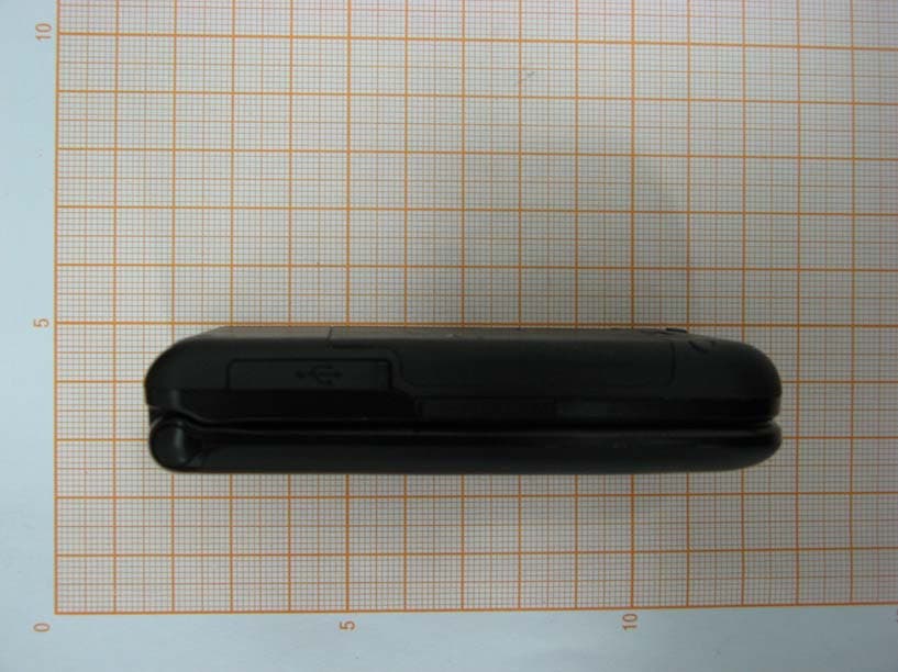
RWZV870
Apr 24, 2007CDMA 1X EVDO/GSM Digital Mobile Phone
Equipment Class
PCE - PCS Licensed Transmitter held to ear
RWZ-6711
Mar 15, 2007GSM850 AND PCS1900 (Mobile Phone)
Equipment Class
PCE - PCS Licensed Transmitter held to ear
RWZ-A320A
Dec 22, 2005Tri Band GSM Mobile Phone
Equipment Class
PCE - PCS Licensed Transmitter held to ear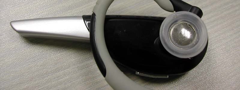
RWZ-BTH003
Nov 17, 2005Bluetooth Headset
Equipment Class
DSS - Part 15 Spread Spectrum Transmitter