RYK-OA200Wireless Outdoor AP
SparkLAN Communications, Inc.
Click to zoom
Application Details
- Equipment Class
- DTS - Digital Transmission System
- Date of Grant
- Aug 03, 2006
- Application Purpose
- Original Equipment
- Date of Application
- Aug 03, 2006
- Equipment Note
- Wireless Outdoor AP
- Frequency Range
- 5745.00000000 - 5825.00000000
- Country
- Taiwan
Documents & Files
Document Text
Text extracted from the exhibit documents filed with the FCC. Open a document above to read the original.
Users Manual
User’s Guide 0 OA200 Outdoor 802.11ag AP User’s Manual Version 1.0 User’s Guide 1 Copyright Statement No part of this publication may be reproduced, stored in a retrieval system, or transmitted in any form or by any means, whether electronic, mechanical, photocopying, recording, or otherwise without the prior writing of the publisher. MAY. 2005 User’s Guide 2 Contents 1. Introduction.................................................................................................................3 2. Safety Notification.......................................................................................................4 3. Outdoor AP default setting........................................................................................5 4. How to Configuring the Dual Band AP.....................................................................6 4.1 Setup – Network Setup.............................................................................................7 4.2 Wireless – Basic Wireless Settings........................................................................8 4.3 Wireless – Wireless Mode........................................................................................9 4.4 Wireless MAC Filter................................................................................................10 4.5 Wireless – Wireless Security.................................................................................11 4.6 Wireless – Advanced Wireless Settings...............................................................12 4.7 Administration – Management...............................................................................15 4.8 Administration – Reboot AP..................................................................................16 4.9 Administration – Firmware Upgrade.....................................................................17 4.10 Administration – Factory Defaults......................................................................18 4.11 Status – Local Network.........................................................................................19 4.12 Status – Wireless Network...................................................................................20 4.13 Status – Wireless Statistics.................................................................................21 5. Troubleshooting – Q & A..........................................................................................22 User’s Guide 3 1. Introduction Thank you for purchasing your Wireless 802.11ag Outdoor AP. This user guide will assist you with the installation procedure. The package you have received should contain the following items: ß Wireless 802.11ag Outdoor AP ß Quick Installation Guide ß User Manual CD-ROM ß POE Host/Cord ß Waterproof RJ-45connector ß Mount kit package ß Reset bar ß RF cable x 2 Note: if anything is missing, please contact your vendor User’s Guide 4 2. Safety Notification Your Wireless AP should be placed in a safe and secure location. To ensure proper operation, please keep the unit away from water and other damaging elements. Please read the user manual thoroughly before you install the device. The device should only be repaired by authorized and qualified personnel. ß Please do not try to open or repair the device yourself. ß Do not place the device in a damp or humid location, i.e. a bathroom. ß The device should be placed in a sheltered and non-slip location within a temperature range of +5 to +40 Celsius degree. ß Please do not expose the device to direct sunlight or other heat sources. The housing and electronic components may be damaged by direct sunlight or heat sources. User’s Guide 5 3. Outdoor AP default setting User Password admin IP Address 192.168.1.250 Subnet Mask 255.255.255.0 RF ESSID A band: wlan-a G band: wlan-g Channel A band: Auto G band: 6 Mode G band: Mixed Encryption Disabled User’s Guide 6 4. How to Configuring the Dual Band AP START UP & LOGIN In order to configure the Wireless 11ag AP, you must use web browser and manually input http://192.168.1.250 into the Address box and press Enter. The Main Page will appear. In order to configure the Wireless 11ag AP, you must input the password into the Password box and leave blank on the User Name box. The default password is “admin”. Once you have logged-in as administrator, it is a good idea to change the administrator password to ensure a secure protection to the Wireless 11ag AP. The Security Settings section described later in this manual describes how to change the password. Once you have input the correct password and logged-in, the screen will change to the Setup page screen. TURN ON POWER SUPPLY Quick power cycle would caused system corruption. When power on, be careful not to shut down in about 5 seconds, because data is writing to the flash. User’s Guide 7 4.1 Setup – Network Setup This following screen contains all of the AP's basic setup functions. Most users will be able to configure the AP and get it working properly using the default settings. Network Setup Identity Device Name: These fields allow you to input a host name for the AP. Local Area Network ♦ Dynamic: If your LAN supports DHCP assigning dynamic IP address then please select this type. ♦ Static IP: This’ s default connection type. If you are required to use a fixed IP address to connect to the LAN, then select Static IP. IP Address: This’ s the AP’s IP address. Subnet Mask: This’ s the AP’s Subnet Mask. Default Gateway: This’ s the AP’s Gateway Address. Those above items can be adjusted that depends on real network architecture if it is necessary. Change these settings as described here and click the Apply button to apply your changes or click Cancel to cancel your changes. For additional information, click Help. MAKE CORRECT NETWORK SETTINGS OF YOUR COMPUTER To change the configuration, use Internet Explorer (IE) or Netscape Communicator to connect the WEB management 192.168.1.250. User’s Guide 8 4.2 Wireless –…
Text truncated - open the document above for the full version.
Users Manual
OA200 Outdoor 802.11ag AP Quick Installation Guide Version 1.0 Content 1. Introduction .......................................................... 3 2. Operating Mode.................................................... 4 3. Hardware Installation........................................... 6 4. Quick Setup Guide............................................... 11 5. Waterproof RJ-45 Connector Assembly ........... 15 3 1. Introduction 1.1 Purpose This document provides information and procedures on hardware installation, setup and management of the IEEE 802.11ag AP Bridge. 1.2 Overview Access Point with Rugged Housing for Application OA200 Wireless11ag AP Bridge provides quality connectivity for Wi-Fi networks. This device is ideal for rugged environments and application. Multiple Operating Modes OA200 Wireless11ag AP Bridge provides 3 operating modes. There are AP, AP Repeater and Wireless Client. When it is set to AP mode, it connects wireless clients to a wired network. In AP Repeater mode, it can extend the communication distance of wireless connection. Finally, in Wireless Wireless client mode, AP auto scan for specific AP (remote AP's SSID), then set up connection to it as a client. Wi-Fi Compliant Device OA200 is Wi-Fi compliant device which ensures the network compatibility. High Performance for Wireless Coverage OA200 designs to support large areas. This unit is built-in high power RF module. Installation OA200 is very easy to install and set up. Power over Ethernet support offers the power for this unit and decreases most effort on installation. 4 2. Operating Mode OA200 provides 3 kinds of operating mode for application. AP mode AP Repeater mode WDS mode 2.1 AP mode In AP mode, it can connect multiple wireless clients to a wired network. 2.2 AP Repeater mode AP Repeater mode allows OA200 to communicate with other 802.11ag APs while functioning in AP mode, and to extend your Wireless Network coverage. It is set by SSID 5 2.3 WDS mode In this mode, it allows wireless connection between two or more wired and wireless networks, such as two networks with the same sub-network in different buildings. For building-to-building wireless connection, each building should implement one OA200 as WDS. In this case, the OA200 can act as a wireless bridge between the two wired and wireless networks. Please fill in remote AP’s MAC address in “WDS links” space. 2.4 Wireless Client mode AP auto scan for specific AP (remote AP's SSID), then set up connection to it as a client. 6 3. Hardware Installation 3.1 LED Description There are 3 LEDs on the right side of OA200. 1. LInk LED Off: No LAN connection available On: LAN connection OK 2. 11g LED Off: no activity Blinking: sending and receiving data 3. 11a LED Off: no activity Blinking: sending and receiving data 7 3.2 Mount Kit Installation 1. Assemble part 1of the mount kit at the rear of OA200, shown in the above figure. 2. If you are mounting the Access Point on a wall, first install the bracket 2 of the mounting kit to a suitable position. Assemble the back of the OA200 housing to the bracket subsequently. 3. If you are mounting the OA200 to a pole, first install the bracket 2 and the clip 3of the mounting kit to a strong pole. Assemble the rear of the OA200 housing to the bracket subsequently. 4. Insert the LAN cable to a Power over Ethernet socket. Make sure the power LED and LAN link LED is light up. 8 3.3 Power over Ethernet Installation 1. Connect the Ethernet cable from the OA200 to PoE hub (LAN out). 2. Connect a second Ethernet cable from the LAN-IN port of the PoE adapter to a free port of a switch or hub within the local network. Please refer to the above figure. 9 3.4 Hardware Reset to default settings You can reset the wireless bridge unit’s settings to factory defaults by pushing reset button using reset bar. The reset button is located and hidden inside of the rear panel as above figure. Please refer to the following steps to perform the Hardware Reset. 10 1. Please unscrew the screw part as above figure. 2. Please use the reset bar to reach the reset button. Press it and hold on for approx 10 seconds. 3. Release the reset button, the device will reboot and all configurations will be set to factory default settings automatically. 3.5 Antenna installation on OA200 antenna inside box, so the external antenna is necessary for this unit. Please find the RP-SMA Antenna connector on the rear side of this box. Usually, it should be a low loss RF cable connected between OA200N and antenna. For decrease the signal loss, we strongly suggest using RF cable with high quality and the length should be as short as possible. There are two RP-SMA types connector at the rear side. One is Antenna 1, the other is Antenna 2 11 4. Quick Setup Guide AP Default Settings The default settings are shown as the following: User Password admin IP Address 192.168.1.250 Subnet Mask 255.255.255.0 RF ESSID A band: wlan-a G band: wlan-g Channel A band: Auto G band: 6 Mode G band: Mixed Encryption Disabled 12 Step1 START UP & LOGIN In order to configure the OA200, you must use your web browser and manually input http://192.168.1.250 into the Address Box and press Enter. The Main Page will appear. To start configure the OA200, you must input password “admin” on the password section. Once you have logged-in as administrator, it is ideal to change the administrator password to ensure a secure protection to the Wireless 11ag AP. Please refer to the Security Settings in the later section, which describes how to change the password. Once you have input the correct password and logged-in, the screen will change to the Setup page screen. 13 Step2 Local Area Network: This is OA200 IP Address and Subnet Mask as seen on the internal LAN. The default value is 192.168.1.250 for IP Address and 255.255.255.0 for Subnet Mask. Please Click “Apply” button to save your settings once you have any change. 14 Step3 Please select the antenna for each band. After completed the setting and hardwar…
Text truncated - open the document above for the full version.
Attestation Statements
Spark Lan Communication, Inc. August 3, 2006 Federal Communications Commission Authorization and Evaluation Division Spark Lan Communication, Inc. company hereby to declare that the device (Model type: OA-200) is an outdoor AP so the frequency 5150MHZ ~5250MHz, 5250MHz ~ 5350MHz will be disabled by firmware. Sincerely Spark Lan Communication
Cover Letter(s)
Chris Harvey From: amanda.wu [[email protected]] on behalf of application [[email protected]] Sent: Friday, July 07, 2006 6:05 AM To: [email protected] Cc: [email protected]; [email protected] Subject: Re:SparkLAN Communications, Inc., FCC ID: RYK-OA200, Assessment NO.: AN06T5886 (DTS), Notice#1 Attachments: OA-200 DoC letter for Laboratory.pdf; OA-200 Declaration Letter from Manufacturer.pdf; OA- 200 BlkDia Revised 0630.pdf; OA-200 Ant. spec Revsied 0707.pdf; OA-200 User manual Revised 0706.pdf; OA-200 Schem Revised 0706.pdf; OA-200 Quick Installation Guide.pdf Page 1 of 3 7/10/2006 Dear Chris: Please see my reply as below. Thank you for help. Best Regards Amanda Dear Gina Lo, You are listed as the technical contact for the above referenced application. The following items must be addressed before the review can be completed: 1. Please provide the Installation Guide which is mentioned in the Users Manual. Ans: Please see the attachemt as installation guide. 2. The antenna specification provided indicates an antenna gain of 5dBi (3.16dB numeric gain) from 2.4GHz to 5.825GHz, which seems unrealistic. Please provide more antenna gain details. <charvey- [email protected]> 2006/06/24 06:03 PM 收件人: <[email protected]> 副本抄送: <[email protected]>, <[email protected]> 主旨: SparkLAN Communications, Inc., FCC ID: RYK-OA200, Assessment NO.: AN06T5886 (DTS), Notice#1 Ans: Please see the antenna spec. 3. Please describe how this device complies with the unique antenna connector requirements of FCC 15.203 for all the RF connectors on the enclosure, antennas, adaptors and cables for this device. Ans: Please see the installation guide. 4. The internal Photo exhibit shows several EMI modifications performed to the sample tested. Please provide a declaration from the manufacturer that the equivalent modifications, including the ferrites inside and on the cables, will be performed on all production units of this device. Ans: Client provided the declaration form. 5. The Users Manual exhibit does no have any RF Exposure guidance/notice to the installer/user regarding the need to maintain at least 20cm separation to this device. Please update the installer/user information to include RF exposure information Ans: Warning Statments had been added into the user manual. 6. Please explain how the units provided for the US market have only FCC approved channels available to the user. Ans: Please see page 22 on user manual. 7. The Block Diagram shows a 4-Port LAN, but the device only has one Ethernet Port. Please explain and correct the exhibits as needed. Ans: The 4-port LAN is for reserve. please have the revised block diagrams and scemeatics. 8. The tests were performed in October and November of 2005. Please have the laboratory provide a declaration that the measurements are still valid. Ans: Please have the attachment. Please note that a separate request for the UNII application for this device will be sent separately. The items indicated above must be submitted before processing can continue on the above referenced application. Failure to provide the requested information within 30 days of the original e-mail date may result in application dismissal and forfeiture of the filing fee. Also, please note that partial responses increase processing time and should not be submitted. Any questions about the content of Page 2 of 3 7/10/2006 this correspondence should be directed to the e-mail address listed below the name of the sender. Best regards, Chris Harvey [email protected] Page 3 of 3 7/10/2006
Cover Letter(s)
Chris Harvey From: amanda.wu [[email protected]] on behalf of application [[email protected]] Sent: Thursday, July 20, 2006 5:57 AM To: [email protected] Subject: Re:SparkLAN Communications, Inc., FCC ID: RYK-OA200, Assessment NO.: AN06T5886, Notice#2 Attachments: OA-200 ExtPho Revised 0720.pdf; OA-200 IntPho Revised 0720.pdf; OA-200 OpDes Revised 0720.pdf Page 1 of 2 7/20/2006 Dear Charvey: Please see my reply, thank you. Best Regards, Amanda Dear Gina Lo, I have received and reviewed your responses to the Notice #1 for the above referenced TCB application. Item #3 from Notice #1 has not yet been addressed. The photos show what appear to be N-Connectors on the rear side of this unit, with N-cables and N to RP-SMA connectors. The manual just indicates that this device is supplied with RP-SMA connectors. The FCC requires that compliance with FCC 15.203 requires unique connectors for the entire RF path OR the device requires Professional Installation. Please describe how this device complies with the unique antenna connector requirements of FCC 15.203 for all the RF connectors on the enclosure, antennas, adaptors and cables for this device. Ans: The rear side of the EUT is a RN female connector, therefore the RN-male to RSMA-female converter can apply on the EUT directly with a RSMA-male antenna. There is another configuration with extension cables apply to it, i.e. apply the RN-RN male cable to the RN female connector of the EUT, after that, apply the RN-RN female cable on the RN-RN male cable. RN-RN female cable is then connect to the antenna thru a RN-male to RSMA-female converter. Please refer to the attached <[email protected]> 2006/07/12 01:04 AM 收件人: <[email protected]> 副本抄送: <[email protected]> 主旨: SparkLAN Communications, Inc., FCC ID: RYK-OA200, Assessment NO.: AN06T5886, Notice#2 revised documents for detail description. The items indicated above must be submitted before processing can continue on the above referenced application. Failure to provide the requested information within 30 days of the original e-mail date may result in application dismissal and forfeiture of the filing fee. Also, please note that partial responses increase processing time and should not be submitted. Any questions about the content of this correspondence should be directed to the e-mail address listed below the name of the sender. Best regards, Chris Harvey [email protected] Page 2 of 2 7/20/2006
Cover Letter(s)
Chris Harvey From: lucy.tsai [[email protected]] Sent: Friday, August 04, 2006 3:02 AM To: Chris Harvey Cc: 'application'; [email protected] Subject: Re:RE: RE: RE: RE: Re:RE: RE: SparkLAN Communications, Inc., FCC ID: RYK-OA200, Assessment NO.: AN06T5889, Notice#1 Attachments: OA-200 Declaration Letter 0803.pdf; OA-200 OpDes Revised 0804.pdf; OA-200 Quick Installation Guide 0804.pdf; OA-200 User manual Revised 0804.pdf Page 1 of 10 8/4/2006 Dear Chris, This is the final confirmation from SparkLAN for cancelling the UNII filing. All related documents as theory of operation, user manual/installation guide and customer declaration regarding disable UNII band have been revised again and attached. Please have a check again and if no other problem, please help to issue the grant for DTS portion. Thank you. Best Regards, Lucy Lucy, this is not just a problem with the name ‘Outdoor AP.’ This device is designed to be outdoor pole mounted, the installation images show this mounted to a tower or on top of a building. This device is intended to be used outdoors and therefore including the indoor-only 5.15-5.25 GHz band is not appropriate / allowed. The 5.15-5.25 GHz band is intended for desktop devices that are clearly intended for use indoors, and have warnings in the manual. I hope that I am being clear on this issue. This outdoor device can not be approved to use the indoor band. Please let me know if you have any further questions. Best regards, Chris Harvey "Chris Harvey" <[email protected]> 2006/08/02 08:13 PM 收件人: "'lucy.tsai'" <[email protected]> 副本抄送: "'application'" <[email protected]>, <[email protected]> 主旨: RE: RE: RE: RE: Re:RE: RE: SparkLAN Communications, Inc., FCC ID: RYK-OA200, Assessment NO.: AN06T5889, Notice#1 [email protected] From: lucy.tsai [mailto:[email protected]] Sent: Tuesday, August 01, 2006 9:59 PM To: Chris Harvey Cc: 'application'; [email protected] Subject: Re:RE: RE: RE: Re:RE: RE: SparkLAN Communications, Inc., FCC ID: RYK-OA200, Assessment NO.: AN06T5889, Notice#1 Dear Chris, At the beginning, they did want to disable 5.15-5.25GHz to meet term of "the outdoor AP", however, as you know that they missed July 19, the target date of getting UNII certificate without DFS test. So now by talking to them, they then decided to keep 5.15-5.25GHz and disable 5.25- 5.35GHz, so the product name will be revised as well. This is the whole story and any misunderstanding please let us know, thank you. Best Regards, Lucy Lucy, please explain how you will revise the UNII test report. As I understand, they will disable the 5.15-5.25GHz indoor band because their device is an Outdoor AP and they will disable the 5.25-5.35GHz band because they do not have DFS compliance. There are no other UNII bands in this device so they do not need a UNII test report. They will need to make sure they have n o other UNII references in their other exhibits for the DTS application. Please let me know if you have any questions. Best regards, Chris Harvey From: lucy.tsai [mailto:[email protected]] Sent: Tuesday, August 01, 2006 9:20 PM "Chris Harvey" <[email protected]> 2006/08/02 09:40 AM 收件人: "'lucy.tsai'" <[email protected]> 副本抄送: "'application'" <[email protected]>, <[email protected]> 主旨: RE: RE: RE: Re:RE: RE: SparkLAN Communications, Inc., FCC ID: RYK-OA200, Assessment NO.: AN06T5889, Notice#1 Page 2 of 10 8/4/2006 To: Chris Harvey Cc: 'application'; [email protected] Subject: Re:RE: RE: Re:RE: RE: SparkLAN Communications, Inc., FCC ID: RYK-OA200, Assessment NO.: AN06T5889, Notice#1 Dear Chris, Got and I will guide the customer to revise the user manual and provide ther revised UNII test report to you asap. Thank you for your continuous focus on this project. Best Regards, Lucy Lucy, I received a reply from CCS-TW stating the following to my question: 10. This device is called an Outdoor AP, but the 5.15 - 5.25GHz band is Indoor Use only. This discrepancy seems to be very confusing, and is likely to confuse users. Ans: This device is an outdoor AP, client provide a cover letter to declarate that they will disable 5150-5250 MHz. If SparkLAN is keeping the 5.15-5.25 GHz Band then they must restrict this to Indoor Use. Why is this Outdoor AP going to have the indoor-only band? Best regards, Chris Harvey From: lucy.tsai [mailto:[email protected]] Sent: Tuesday, August 01, 2006 11:56 AM To: Chris Harvey Cc: 'application'; 'Chris Harvey'; [email protected] Subject: Re:RE: Re:RE: RE: SparkLAN Communications, Inc., FCC ID: RYK-OA200, Assessment NO.: AN06T5889, Notice#1 "Chris Harvey" <[email protected]> 2006/08/02 12:40 AM 收件人: "'lucy.tsai'" <[email protected]> 副本抄送: "'application'" <[email protected]>, <[email protected]> 主旨: RE: RE: Re:RE: RE: SparkLAN Communications, Inc., FCC ID: RYK-OA200, Assessment NO.: AN06T5889, Notice#1 Page 3 of 10 8/4/2006 Dear Chris, Please review DTS portion in advance but as for UNII portion, customer still wants to keep 5.15-5.25GHz UNII band. They will revise the user manual again and also revise the 5.25- 5.35GHz UNII band from the original UNII report. But a question regarding remove 5.25-5.35GHz band needs to double confirm with you. Should we need to measure the middle and high channels for the 5.15-5.25GHz UNII portion since the original middle/high channels are allocated in the range of 5.25-5.35GHz? Best Regards, Lucy Amanda, I now see what you were saying. You wish to Dismiss (cancel) the entire UNII portion of this device, which means to dismiss the AN06T5889 assessment number and proceed with only the DTS portion under AN06T5886. I have looked into the test report exhibit for AN06T5886 DTS portion and find no references to UNII or 5.15-5.35GHz. I will continue this review of AN06T5886 (DTS) today, including the new Users Manual and Operational Descriptions submitted on 7/28. Best regards, Chris Harvey From: Chris Harvey [mailto:[email protected]] Sent: Tuesday, August 01, 2006 6:54…
Text truncated - open the document above for the full version.
External Photos
Compliance Certification Services Inc. Report No: 50923005 Date of Issue: November 9, 2005 Page 1 Total Page: 11 Rev. 00 EXTERNAL PHOTOGRAPHS OF EUT Compliance Certification Services Inc. Report No: 50923005 Date of Issue: November 9, 2005 Page 2 Total Page: 11 Rev. 00 Compliance Certification Services Inc. Report No: 50923005 Date of Issue: November 9, 2005 Page 3 Rev.00 Compliance Certification Services Inc. Report No: 50923005 Date of Issue: November 9, 2005 Page 4 Rev.00 Power over Ethernet Hub Compliance Certification Services Inc. Report No: 50923005 Date of Issue: November 9, 2005 Page 5 Rev.00 Compliance Certification Services Inc. Report No: 50923005 Date of Issue: November 9, 2005 Page 6 Rev.00 Compliance Certification Services Inc. Report No: 50923005 Date of Issue: November 9, 2005 Page 7 Rev.00
Internal Photos
Compliance Certification Services Inc. Report No: 50923005 Date of Issue: November 9, 2005 Page 8 Rev.00 INTERNAL PHOTOGRAPHS OF EUT Compliance Certification Services Inc. Report No: 50923005 Date of Issue: November 9, 2005 Page 9 Rev.00 Compliance Certification Services Inc. Report No: 50923005 Date of Issue: November 9, 2005 Page 10 Rev.00 Power over Ethernet Hub Compliance Certification Services Inc. Report No: 50923005 Date of Issue: November 9, 2005 Page 11 Rev.00
Parts List/Tune Up Info
18 ±0.3 ELECTRICAL PERFORMANCE :1.Impedance : 50 ohms2.Frequency Range :2.4--5.825GHz3.V.S.W.R : 2.0 max4.Gain:5dBi 4 6 132 ±1.0 7.8 B C D SEE ECN SEE ECN SEE ECN 04-10804-129 04-284 05-044 2004/04/23 2004/08/06 2005/02/15 Jimmy : 0-0.3mm 2.4-5.825GHz Tri-Band RP-SMA Plug Antenna W620-132-D200 1 2 3 4 A NEW RELEASE 2004/03/23 D 1 1 1.5:1 Jimmy ZEKE 2005/02/15 2004/02/23 HOLES UNDER 0.5 ±0.1 ANGULAR DIMENSIONS ±5 UNLESS OTHERWISE SPECIFIED ALL TOLERANCES ARE : A 1 B FINISH: 2 PLACE DECIMALS ±0.25 1 PLACE DECIMAL ±0.5 INTEGRAL DIMENSIONS ±1 DIMENSION METERIAL: 2 ANGLE ROUGHNESS C D 3 4 A B DESCRIPTION REV. C ECN DATE D 1 2 3 4 SCALE: UNIT: Precise Corp. APVD BY: ENGR BY: DRAWED BY: DATE:DATE:DATE: DWG NO:DWG TITLE: OF SHEET SIZE: MM A4 REV. DRAWN RP-S MA Plug Bras s Gold 4u" SHELL Black Cr. PC/ABS Black PC/ABS Black Black Cr. Black FINIS HED RP-S MA Plug Bras s Gold 4u" SHELL Black Cr. PC/ABS Black PC/ABS Black Black Cr. Black FINIS HED -B-2400-E CCS WUGU Antenna Pattern Job No.:-B-2400-E Date:2006/5/11 Time: 03:53 Temp.()/Hum.(%):25/80% Tested by: Center freq.(MHz): 2400 Polarization : E Plane Max gain(dBi):1.05 Min gain(dBi):-40.41 Avg gain(dBi):-2.60 -B-2400-H CCS WUGU Antenna Pattern Job No.:-B-2400-H Date:2006/5/11 Time: 04:09 Temp.()/Hum.(%):25/80% Tested by: Center freq.(MHz): 2400 Polarization : H Plane Max gain(dBi):2.89 Min gain(dBi):0.76 Avg gain(dBi):2.03 -B-2450-H CCS WUGU Antenna Pattern Job No.:-B-2450-H Date:2006/5/11 Time: 04:08 Temp.()/Hum.(%):25/80% Tested by: Center freq.(MHz): 2450 Polarization : H Plane Max gain(dBi):2.27 Min gain(dBi):0.94 Avg gain(dBi):1.72 -B-2450-E CCS WUGU Antenna Pattern Job No.:-B-2450-E Date:2006/5/11 Time: 03:51 Temp.()/Hum.(%):25/80% Tested by: Center freq.(MHz): 2450 Polarization : E Plane Max gain(dBi):1.05 Min gain(dBi):-23.80 Avg gain(dBi):-2.80 -B-2500-H CCS WUGU Antenna Pattern Job No.:-B-2500-H Date:2006/5/11 Time: 04:11 Temp.()/Hum.(%):25/80% Tested by: Center freq.(MHz): 2500 Polarization : H Plane Max gain(dBi):2.32 Min gain(dBi):0.91 Avg gain(dBi):1.73 -B-2500-E CCS WUGU Antenna Pattern Job No.:-B-2500-E Date:2006/5/11 Time: 03:54 Temp.()/Hum.(%):25/80% Tested by: Center freq.(MHz): 2500 Polarization : E Plane Max gain(dBi):1.35 Min gain(dBi):-28.67 Avg gain(dBi):-2.29 -B-5150-H CCS WUGU Antenna Pattern Job No.:-B-5150-H Date:2006/5/11 Time: 04:13 Temp.()/Hum.(%):25/80% Tested by: Center freq.(MHz): 5150 Polarization : H Plane Max gain(dBi):2.64 Min gain(dBi):-1.04 Avg gain(dBi):1.17 -B-5150-E CCS WUGU Antenna Pattern Job No.:-B-5150-E Date:2006/5/11 Time: 03:56 Temp.()/Hum.(%):25/80% Tested by: Center freq.(MHz): 5150 Polarization : E Plane Max gain(dBi):1.76 Min gain(dBi):-23.62 Avg gain(dBi):-3.68 -B-5250-H CCS WUGU Antenna Pattern Job No.:-B-5250-H Date:2006/5/11 Time: 04:15 Temp.()/Hum.(%):25/80% Tested by: Center freq.(MHz): 5250 Polarization : H Plane Max gain(dBi):2.39 Min gain(dBi):-0.24 Avg gain(dBi):1.34 -B-5250-E CCS WUGU Antenna Pattern Job No.:-B-5250-E Date:2006/5/11 Time: 03:59 Temp.()/Hum.(%):25/80% Tested by: Center freq.(MHz): 5250 Polarization : E Plane Max gain(dBi):1.26 Min gain(dBi):-21.63 Avg gain(dBi):-3.55 -B-5350-H CCS WUGU Antenna Pattern Job No.:-B-5350-H Date:2006/5/11 Time: 04:18 Temp.()/Hum.(%):25/80% Tested by: Center freq.(MHz): 5350 Polarization : H Plane Max gain(dBi):2.63 Min gain(dBi):-0.35 Avg gain(dBi):1.39 -B-5350-E CCS WUGU Antenna Pattern Job No.:-B-5350-E Date:2006/5/11 Time: 04:01 Temp.()/Hum.(%):25/80% Tested by: Center freq.(MHz): 5350 Polarization : E Plane Max gain(dBi):0.90 Min gain(dBi):-44.46 Avg gain(dBi):-3.61 -B-5725-H CCS WUGU Antenna Pattern Job No.:-B-5725-H Date:2006/5/11 Time: 04:20 Temp.()/Hum.(%):25/80% Tested by: Center freq.(MHz): 5725 Polarization : H Plane Max gain(dBi):2.96 Min gain(dBi):-2.73 Avg gain(dBi):0.81 -B-5725-E CCS WUGU Antenna Pattern Job No.:-B-5725-E Date:2006/5/11 Time: 04:03 Temp.()/Hum.(%):25/80% Tested by: Center freq.(MHz): 5725 Polarization : E Plane Max gain(dBi):0.43 Min gain(dBi):-22.59 Avg gain(dBi):-3.69 -B-5850-H CCS WUGU Antenna Pattern Job No.:-B-5850-H Date:2006/5/11 Time: 04:22 Temp.()/Hum.(%):25/80% Tested by: Center freq.(MHz): 5850 Polarization : H Plane Max gain(dBi):3.47 Min gain(dBi):-2.08 Avg gain(dBi):1.23 -B-5850-E CCS WUGU Antenna Pattern Job No.:-B-5850-E Date:2006/5/11 T…
Text truncated - open the document above for the full version.
Contact Information
Applicant
Grady Lin(Manager)
Test Firm
Compliance Certification Services Inc.Harris Lai
Technical Specifications
| # | Rule Parts | Frequency Range | Power Output |
|---|---|---|---|
| 2 | 15C | 5.75 GHz - 5.83 GHz | 50.35 mW |
Other Applications from SparkLAN Communications, Inc.
RYK-AP6275SDSR
Jan 11, 2023IEEE 802.11ax/ac/a/b/g/n 2x2 WiFi with Bluetooth5.2 M.2 LGA Type 1216 Module
Equipment Class
DTS - Digital Transmission System
RYK-WPEQ268AXBT
Dec 01, 2022Wi-Fi 6E BT Half Min PCIe Module
Equipment Class
DTS - Digital Transmission System
RYK-WNFB266AXIBT
Mar 20, 2021IEEE 802.11ax/ac/a/b/g/n 2x2 WiFi with Bluetooth5.0 Combo Module
Equipment Class
NII - Unlicensed National Information Infrastructure TX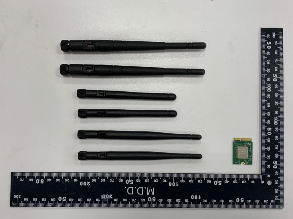
RYK-WNFB265AXIBT
Feb 23, 2021IEEE 802.11ax/ac/a/b/g/n 2x2 WiFi with Bluetooth5.0 Combo Module
Equipment Class
NII - Unlicensed National Information Infrastructure TX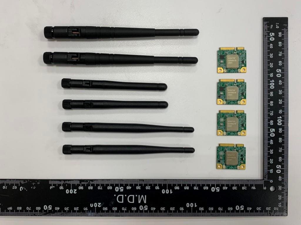
RYK-WPEB265AXIBT
Jan 10, 2021IEEE 802.11ax/ac/a/b/g/n 2x2 WiFi with Bluetooth5.0 Combo Module
Equipment Class
JBP - Part 15 Class B Computing Device Peripheral