RYK-WCM100802.11g Wireless Ethernet Adapter
SparkLAN Communications, Inc.
Click to zoom
Application Details
- Equipment Class
- DTS - Digital Transmission System
- Date of Grant
- Mar 22, 2006
- Application Purpose
- Original Equipment
- Date of Application
- Mar 21, 2006
- Equipment Note
- 802.11g Wireless Ethernet Adapter
- Frequency Range
- 2412.00000000 - 2462.00000000
- Country
- Taiwan
Documents & Files
Document Text
Text extracted from the exhibit documents filed with the FCC. Open a document above to read the original.
Users Manual
802.11g Wireless Ethernet Adapter User’s Manual Version 1.0 User’s Guide 1 Federal Communication Commission Interference Statement This equipment has been tested and found to comply with the limits for a Class B digital device, pursuant to Part 15 of the FCC Rules. These limits are designed to provide reasonable protection against harmful interference in a residential installation. This equipment generates, uses and can radiate radio frequency energy and, if not installed and used in accordance with the instructions, may cause harmful interference to radio communications. However, there is no guarantee that interference will not occur in a particular installation. If this equipment does cause harmful interference to radio or television reception, which can be determined by turning the equipment off and on, the user is encouraged to try to correct the interference by one of the following measures: - Reorient or relocate the receiving antenna. - Increase the separation between the equipment and receiver. - Connect the equipment into an outlet on a circuit different from that to which the receiver is connected. - Consult the dealer or an experienced radio/TV technician for help. This device complies with Part 15 of the FCC Rules. Operation is subject to the following two conditions: (1) This device may not cause harmful interference, and (2) this device must accept any interference received, including interference that may cause undesired operation. FCC Caution: Any changes or modifications not expressly approved by the party responsible for compliance could void the user's authority to operate this equipment. IMPORTANT NOTE: FCC Radiation Exposure Statement: This equipment complies with FCC radiation exposure limits set forth for an uncontrolled environment. This equipment should be installed and operated with minimum distance 20cm between the radiator & your body. This transmitter must not be co-located or operating in conjunction with any other antenna or transmitter. The WCM-100 ( FCC ID: RYK-WCM100 ) is limited in CH1~CH11 for 2.4 GHz by specified firmware controlled in U.S.A. User’s Guide 2 Copyright Statement No part of this publication may be reproduced, stored in a retrieval system, or transmitted in any form or by any means, whether electronic, mechanical, photocopying, recording, or otherwise without the prior writing of the publisher. Mar. 2006 User’s Guide 3 Contents 1. Introduction ............................................................................................................... 4 2. Safety Notification .................................................................................................... 5 3. Hardware Installation................................................................................................ 6 4. Web Management Settings ...................................................................................... 7 4.1 Configuration...............................................................................................................8 4.2 Local Area Network.......................................................................................................9 4.3 Wireless....................................................................................................................11 4.4 Security.....................................................................................................................14 4.5 SNMP Trap Settings....................................................................................................18 4.6 Status Overview.........................................................................................................19 4.7 Upgrade Firmware......................................................................................................20 4.8 Reboot Access Point...................................................................................................21 4.9 Restore Factory Defaults..............................................................................................22 4.10 Configuration Profile Download.....................................................................................23 4.11 Configuration Profile Upload........................................................................................24 5. Appendix.................................................................................................................. 25 6. Troubleshooting ...................................................................................................... 26 User’s Guide 4 1. Introduction Thank you for purchasing 802.11g Wireless Ethernet Adapter. This user guide will assist you with the installation procedure. The package you have received should contain the following items: 802.11g Wireless Ethernet Adapter Quick Installation Guide Combo Cable User Manual CD Note: if anything is missing, please contact your vendor User’s Guide 5 2. Safety Notification Your Wireless Ethernet Adapter should be placed in a safe and secure location. To ensure proper operation, please keep the unit away from water and other damaging elements. Please read the user manual thoroughly before you install the device. The device should only be repaired by authorized and qualified personnel. Please do not try to open or repair the device by yourself. Do not place the device in a damp or humid location, i.e. a bathroom. The device should be placed in a sheltered and non-slip location within a temperature range of +5 to +40 Celsius degree. Please do not expose the device to direct sunlight or other heat sources. The housing and electronic components may be damaged by direct sunlight or heat sources. User’s Guide 6 3. Hardware Installation Front Panel The front panel provides LED’s for device status. Refer to the following table for the meaning of each feature. LED STATUS Description Off No power Green On 1. Power on 2. Reset to default 3. Firmware upgrade (first 1 minute) POWER Gre…
Text truncated - open the document above for the full version.
External Photos
Page 1 CONSTRUCTION PHOTOS OF EUT Page 2
ID Label/Location Info
文件編號: (圖二) 200603005-1 發行日期 : 95/3/20PAGE: 1 Release Date 000E8E073762 YYM0501100001 A. B.
ID Label/Location Info
通訊股份有限公司 n Conmunication Inc. Sec (圖一) (圖三) 標準工時發行版本 : 1.0 (Standard Time) Release Rev
Internal Photos
Page 3 Page 4 Page 5 Page 6
Operational Description
FCC ID: RYK-WCM100 Report No. RF950214L09 Operational Description This device is a 802.11g Wireless Ethernet Adapter which operates in the 2.4GHz frequency spectrum with throughput of up to 54Mbps which OFDM technique will be applied. If the signal to noise radio is too poor which could not support 54Mbps, the 11Mbps data rate with CCK technique will be applied. The transmitter of the EUT is powered by host equipment. The antenna is Dipole antenna without antenna connector. Under normal use condition, the user has to keep at least 20cm separation distance between radiator and the body of the user. The other instruction, please have a look at the users manual.
RF Exposure Info
FCC ID: RYK-WCM100 Report No: SA950214L09 1 RF EXPOSURE REPORT REPORT NO.: SA950214L09 MODEL NO.: WCM-100 ACCORDING: FCC Guidelines for Human Exposure IEEE C95.1 APPLICANT: SparkLAN Communications, Inc. ADDRESS: 3Fl., No. 246, Sec. 1, Neihu Road., Neihu Chiu, Taipei Taiwan 114, R.O.C ISSUED BY: Advance Data Technology Corporation LAB ADDRESS: No. 47, 14th Ling, Chia Pau Tsuen, Lin Kou Hsiang 244, Taipei Hsien, Taiwan, R.O.C. TEST LOCATION: No. 19, Hwa Ya 2nd Rd., Wen Hwa Tsuen, Kwei Shan Hsiang, Taoyuan Hsien 333, Taiwan, R.O.C. FCC ID: RYK-WCM100 Report No: SA950214L09 2 RF Exposure Measurement (Mobile Device) 1. Introduction In this document, we try to prove the safety of radiation harmfulness to the human body for our product. The limit for Maximum Permissible Exposure (MPE) specified in FCC 1.1310 is followed. The Gain of the antenna used in this product is measured in a Fully Anechoic Chamber (FAC) calibrated for antenna measurement in ADT, and also the maximum total power input to the antenna is measured. Through the Friis transmission formula and the maximum gain of the antenna, we can calculate the distance, away from the product, where the limit of MPE is reached. Although the Friis transmission formula is a far field assumption, the calculated result of that is an over-prediction for near field power density. We will take that as the worst case to specify the safety range. 2. RF Exposure Limit According to FCC 1.1310: The criteria listed in the following table shall be used to evaluate the environmental impact of human exposure to radio-frequency (RF) radiation as specified in 1.1307(b) LIMITS FOR MAXIMUM PERMISSIBLE EXPOSURE (MPE) Frequency Range (MHz) Electric Field Strength (V/m) Magnetic Field Strength (A/m) Power Density (mW/cm 2 ) Average Time (minutes) (A)Limits For Occupational / Control Exposures 300-1500......F/3006 1500-100,000......56 (B)Limits For General Population / Uncontrolled Exposure 300-1500......F/15006 1500-100,000......1.030 F = Frequency in MHz FCC ID: RYK-WCM100 Report No: SA950214L09 3 3. Friis Formula Friis transmission formula : Pd = (Pout*G) / (4*pi*r 2 ) where Pd = power density in mW/cm 2 Pout = output power to antenna in mW G = gain of antenna in linear scale Pi = 3.1416 R = distance between observation point and center of the radiator in cm If we know the maximum Gain of the antenna and the total power input to the antenna, through the calculation, we will know the MPE value at distance r. Ref. : David K. Cheng, Field and Wave Electromagnetics, Second Edition, Page 640, Eq. (11-133). 4. EUT Operating condition The software provided by Manufacturer enabled the EUT to transmit and receive data at lowest, middle and highest channel individually. 5. Classification The antenna of this product, under normal use condition, is at least 20cm away from the body of the user. Warning statement to the user for keeping at least 20cm or more separation distance with the antenna should be included in users manual. So, this device is classified as Mobile Device. FCC ID: RYK-WCM100 Report No: SA950214L09 4 6. Test Results 6.1 Antenna Gain The maximum Gain measured in Fully Anechoic Chamber is 0.5dBi or 1.122 (numeric). 6.2 Output Power Into Antenna & RF Exposure value at distance 20cm: 802.11b DSSS modulation Channel Channel Frequency (MHz) Output Power to Antenna (mW) Power Density (mW/cm 2 ) Limit of Power Density (mW/cm 2 ) 1241240.5510.0091.000 6243739.8110.0091.000 11246240.4580.0091.000 802.11g OFDM modulation Channel Channel Frequency (MHz) Output Power to Antenna (mW) Power Density (mW/cm 2 ) Limit of Power Density (mW/cm 2 ) 1241220.0450.0041.000 6243720.0450.0041.000 11246220.2770.0051.000
Test Report
Report No.: RF950214L091Report Format Version 2.0.4 FCC TEST REPORT REPORT NO.: RF950214L09 MODEL NO.: WCM-100 RECEIVED: Mar. 02, 2006 TESTED: Mar. 02 ~ Mar. 14, 2006 ISSUED: Mar. 16, 2006 APPLICANT: SparkLAN Communications, Inc. ADDRESS: 3Fl., No. 246, Sec. 1, Neihu Road., Neihu Chiu, Taipei Taiwan 114, R.O.C ISSUED BY: Advance Data Technology Corporation LAB ADDRESS: 47 14 th Lin, Chiapau Tsun, Linko, Taipei, Taiwan, R.O.C. TEST LOCATION: No. 19, Hwa Ya 2 nd Rd., Kueishan, Taoyuan, Taiwan, R.O.C. This test report consists of 63 pages in total. It may be duplicated completely for legal use with the approval of the applicant. It should not be reproduced except in full, without the written approval of our laboratory. The client should not use it to claim product endorsement by CNLA, A2LA or any government agencies. The test results in the report only apply to the tested sample. No. 2177-01 Report No.: RF950214L092Report Format Version 2.0.4 Table of Contents 1CERTIFICATION........................................................................................................4 2SUMMARY OF TEST RESULTS................................................................................5 2.1MEASUREMENT UNCERTAINTY..............................................................................5 3GENERAL INFORMATION.........................................................................................6 3.1GENERAL DESCRIPTION OF EUT...........................................................................6 3.2DESCRIPTION OF TEST MODES.............................................................................7 3.2.1CONFIGURATION OF SYSTEM UNDER TEST.........................................................7 3.2.2TEST MODE APPLICABILITY AND TESTED CHANNEL DETAIL..............................8 3.3GENERAL DESCRIPTION OF APPLIED STANDARDS...........................................10 3.4DESCRIPTION OF SUPPORT UNITS.....................................................................10 4TEST TYPES AND RESULTS..................................................................................11 4.1CONDUCTED EMISSION MEASUREMENT............................................................11 4.1.1LIMITS OF CONDUCTED EMISSION MEASUREMENT..........................................11 4.1.2TEST INSTRUMENTS..............................................................................................11 4.1.3TEST PROCEDURES..............................................................................................12 4.1.4DEVIATION FROM TEST STANDARD.....................................................................12 4.1.5TEST SETUP...........................................................................................................13 4.1.6EUT OPERATING CONDITIONS.............................................................................13 4.1.7TEST RESULTS.......................................................................................................14 4.2RADIATED EMISSION MEASUREMENT.................................................................20 4.2.1LIMITS OF RADIATED EMISSION MEASUREMENT...............................................20 4.2.2TEST INSTRUMENTS..............................................................................................21 4.2.3TEST PROCEDURES..............................................................................................22 4.2.4DEVIATION FROM TEST STANDARD.....................................................................22 4.2.5TEST SETUP...........................................................................................................23 4.2.6EUT OPERATING CONDITIONS.............................................................................23 4.2.7TEST RESULTS.......................................................................................................24 4.36dB BANDWIDTH MEASUREMENT........................................................................31 4.3.1LIMITS OF 6dB BANDWIDTH MEASUREMENT......................................................31 4.3.2TEST INSTRUMENTS..............................................................................................31 4.3.3TEST PROCEDURE.................................................................................................32 4.3.4DEVIATION FROM TEST STANDARD.....................................................................32 4.3.5TEST SETUP...........................................................................................................32 4.3.6EUT OPERATING CONDITIONS.............................................................................32 4.3.7TEST RESULTS.......................................................................................................33 4.4MAXIMUM PEAK OUTPUT POWER........................................................................39 4.4.1LIMITS OF MAXIMUM PEAK OUTPUT POWER MEASUREMENT.........................39 Report No.: RF950214L093Report Format Version 2.0.4 4.4.2TEST INSTRUMENTS..............................................................................................39 4.4.3TEST PROCEDURES..............................................................................................40 4.4.4DEVIATION FROM TEST STANDARD.....................................................................40 4.4.5TEST SETUP...........................................................................................................40 4.4.6EUT OPERATING CONDITIONS.............................................................................40 4.4.7TEST RESULTS.......................................................................................................41 4.5POWER SPECTRAL DENSITY MEASUREMENT....................................................42 4.5.1LIMITS OF POWER SPECTRAL DENSITY MEASUREMENT..................................42 4.5.2TEST INSTRUMENTS....................................................................................…
Text truncated - open the document above for the full version.
Test Setup Photos
Report No.: RF950214L0960Report Format Version 2.0.4 5 PHOTOGRAPHS OF THE TEST CONFIGURATION CONDUCTED EMISSION TEST Report No.: RF950214L0961Report Format Version 2.0.4 RADIATED EMISSION TEST
Contact Information
Applicant
Grady Lin(Manager)
Technical Contact
Advance Data Technology Corporation (Hwa Ya)Gary Chang
[email protected]886-3-3183232
No. 19, Hwa Ya 2nd Rd., Kwei Shan Hsiang · Taoyuan Hsien · Taiwan
Non-Technical Contact
Advance Data Technology CorporationEllis Wu
[email protected]886-3-3183232
Test Firm
Bureau Veritas CPS (H.K.) Ltd. Taoyuan BranchRichard Chen
Technical Specifications
| # | Rule Parts | Frequency Range | Power Output |
|---|---|---|---|
| 1 | 15C | 2.41 GHz - 2.46 GHz | 41.00 mW |
Other Applications from SparkLAN Communications, Inc.
RYK-AP6275SDSR
Jan 11, 2023IEEE 802.11ax/ac/a/b/g/n 2x2 WiFi with Bluetooth5.2 M.2 LGA Type 1216 Module
Equipment Class
DTS - Digital Transmission System
RYK-WPEQ268AXBT
Dec 01, 2022Wi-Fi 6E BT Half Min PCIe Module
Equipment Class
DTS - Digital Transmission System
RYK-WNFB266AXIBT
Mar 20, 2021IEEE 802.11ax/ac/a/b/g/n 2x2 WiFi with Bluetooth5.0 Combo Module
Equipment Class
NII - Unlicensed National Information Infrastructure TX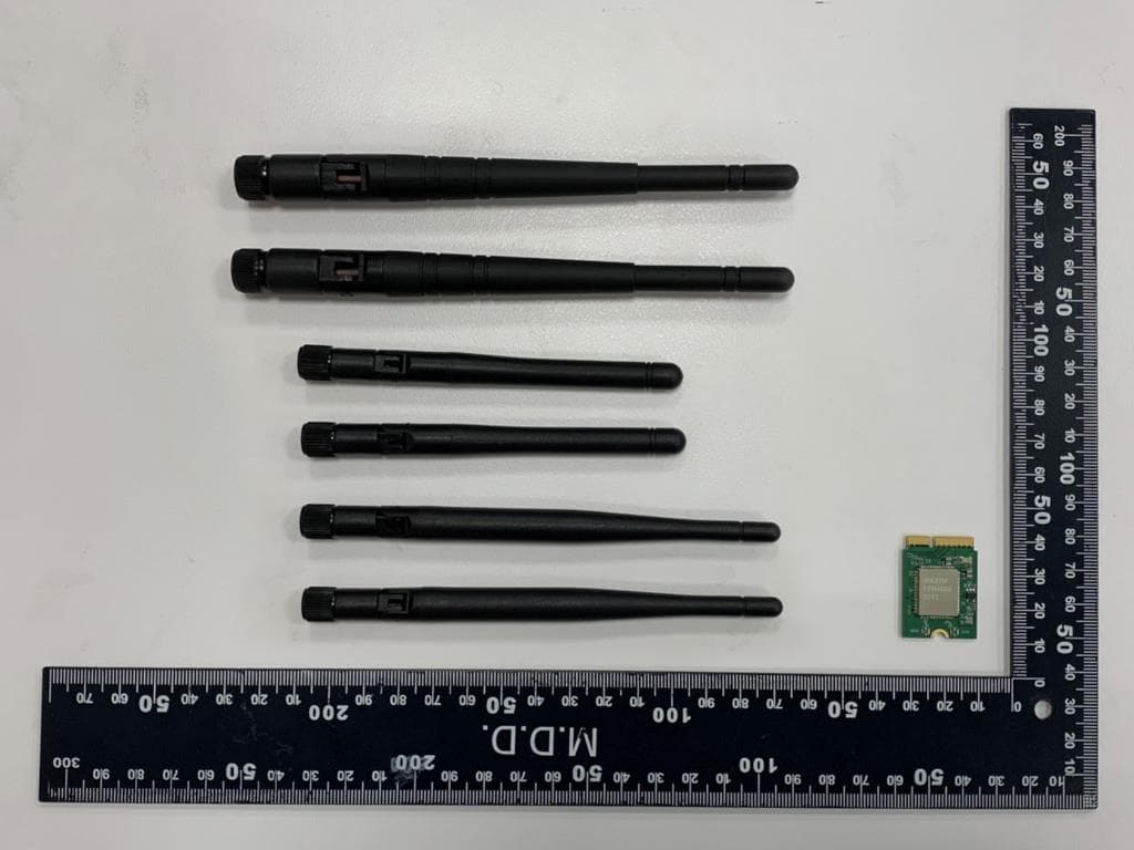
RYK-WNFB265AXIBT
Feb 23, 2021IEEE 802.11ax/ac/a/b/g/n 2x2 WiFi with Bluetooth5.0 Combo Module
Equipment Class
NII - Unlicensed National Information Infrastructure TX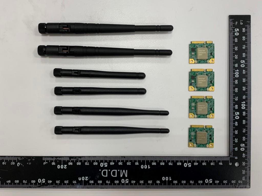
RYK-WPEB265AXIBT
Jan 10, 2021IEEE 802.11ax/ac/a/b/g/n 2x2 WiFi with Bluetooth5.0 Combo Module
Equipment Class
JBP - Part 15 Class B Computing Device Peripheral