RYK-WPER150GN802.11 b/g/n USB Half Mini Card
SparkLAN Communications, Inc.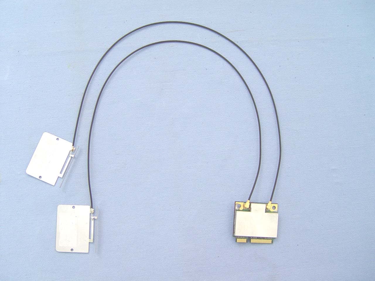
Click to zoom
Application Details
- Equipment Class
- DTS - Digital Transmission System
- Date of Grant
- Jun 06, 2010
- Application Purpose
- Original Equipment
- Date of Application
- Jun 06, 2010
- Equipment Note
- 802.11 b/g/n USB Half Mini Card
- Frequency Range
- 2422.00000000 - 2452.00000000
- Country
- Taiwan
Documents & Files
Document Text
Text extracted from the exhibit documents filed with the FCC. Open a document above to read the original.
Users Manual
1 WPER-150GN IEEE 802.11b/g/n USB Half-Mini-Card Module 2 I. Introduction i. Overview SparkLAN Communications, Inc. introduces the pioneer of the IEEE 802.11b/g/n USB Half-Mini-Card wireless module --- WPER-150GN. The WPER-150GN USB Half-Mini-Card wireless module is a highly integrated wireless local area network (WLAN) solution to let users enjoy the digital content through the latest wireless technology without using the extra cables and cords. It enables a high performance, cost effective, low power, compact solution that easily fits onto one side of a USB Half-Mini-Card. Compliant with the IEEE 802.11b/g/n standard, the WPER-150GN uses Direct Sequence Spread Spectrum (DSSS), Orthogonal Frequency Division Multiplexing (OFDM), BPSK, QPSK, CCK and QAM baseband modulation technologies. A high level of integration and full implementation of the power management functions specified in the IEEE 802.11 standard minimize system power requirements by using WPER-150GN. Longer Range and Faster Speed Comparing to 802.11g technology, 802.11n draft 3.0 standard make big improvement on speed and range. It Increases wireless range by up to 2 times and reduces dead spots in coverage area. The data rate can up to 150Mbps data rate. ii. Features z USB Half-Mini-Card. z Compliant with IEEE802.11n Draft 3.0 standard z 2 antennas to support 1(Transmit) × 1(Receive) Diversity technology z High speed wireless connection up to 150MbpsLow power consumption and high performance z Enhanced wireless security 3 iii. Product Review 1. Connection Mode √ Roaming: a wireless LAN enabled computer can physically move from the operating range of one access point to the other without losing connection. There is a quick association made between new access point and wireless device as the computer traverses from the coverage of one access point to another. √ Range Extension: each wireless LAN enabled computer within the range of access point can communicate with other wireless LAN enabled computers within the range from the access point. √ Wired to wireless LAN connection: the access point will establish a bridge between wireless LAN and other wired counterparts. Infrastructure Mode 4 Ad-hoc Mode It is recommended to choose this mode when there is no access point showed on your wireless network. 5 II. Installation i. System Requirements *Minimum of 64MB system memory *Operating system: XP/Vista * Driver installation ii. Setup: Windows XP OS 1. Find out the Driver, and launch the Setup Wizard 2. Please wait few seconds for wizard to prepare installation 6 3. Please select click [Install] to proceed 4. The Wizard is running installation 7 5. Please wait few seconds for Wizard to setup 6. When it is completed, please click [Finish] 8 iii. Setup: Windows Vista OS Please follow the steps to complete installation. 1. Launch the setup driver 2. When you see the permission dialogue box, please click [Continue] 9 3. Now the Wizard is preparing installation 4. Please click [Install] to proceed 10 5. The system is processing installation 6. Please wait few seconds for Wizard to setup 11 7. When the setup is completed, please click [Finish] 12 III. Network Connection i. For Windows XP OS Please see the following steps to setup network connection for Windows XP. 1. Find the network icon on the desktop shortcut and right-click on it. Choose “View Available Wireless networks” 2. You will see several options, please select one and click [Connect] 13 3. Please wait for few seconds to let system connecting to selected wireless network 4. You may need to type the network key when it is required (if the network doesn’t request the key, the network will connect directly.) 5. Now the selected wireless network is connected 14 6. You can check the connection status by clicking [Status] in the pop-up dialogue 7. Here is the wireless network connection status ii. For Windows Vista OS Following are the instructions to setup wireless connection for Windows Vista. 1. Right-click on the network icon located on desktop shortcut. When you see the dialogue, please click [Connect to a network] 15 2. Choose wireless network within your range and click [Connect] * If selected network is not secure, please choose [Connect anyway] 3. You may need to wait for few seconds when Windows connects to wireless network 16 4. Now the selected wireless network is connected 5. If you want to see the connection status, please right-click on the network you choose and select [Status] 17 6. This is the information of network status 18 IV. Setup for Ad-hoc Mode i. For Windows XP OS If you want to choose Ad-hoc mode, please right-click network icon on desktop shortcut and choose “Open Network Connections”, or go to [Control Panel] and double-click “Network Connection” icon. When you see the “Network Connections” screen, please follow the steps below to setup Ad-hoc mode. 19 1. Double-click “Wireless Network Connection” icon to enter its properties 2. Click "General” tab and double-click the “Internet Protocol (TCP/IP)” item 20 3. Choose “Use the following IP address:” and type the IP address; then click [OK] *Note: the IP address of the other wireless card should be set with the same subnet mask 4. Right-click the “Wireless Network Connection” icon and choose “properties” 21 5. Select “Wireless Network” tab and choose [Add] 6. Type “Network name (SSID)” and choose “Data encryption” if you want to protect the network security 22 7. When you see the dialogue showing your network is unsecured, please click [Continue Anyway] 8. Now your network is in Ad-hoc mode ii. For Windows Vista OS Please follow the steps to setup Ad-hoc mode for Windows Vista. 1. Right-click the Network neighbor to choose “properties,” or you can right-click network icon on desktop shortcut and choose “Network and Sharing Center” 23 2. When you see the “Network and Sharing Center” windows, please select “Manage network connection” bar 24 3. Right-click the connected network icon and choose “Properties” 4. Wh…
Text truncated - open the document above for the full version.
Cover Letter(s)
FCC ID: RYK-WPER150GN Confidentiality Request Pursuant to Sections 0.457 and 0.459 of the Commission’s Rules, the applicant hereby requests confidential treatment of information applied this application as outlined below: 1. Block Diagram 2. Circuit Diagram 3. Operational Description The above materials contain trade secrets and proprietary information not customarily released to the public. The public disclosure of these matters might be harmful to the applicant and provide unjustified benefits to its competitors. The Applicant understands that pursuant to Rule 0.457, disclosure of this Application and all accompanying documentation will not be made before the date of the Grant for this application Signature Name/Title: / Manager Company Name: Address: TEL: FAX:(02)2659-5538/2659-5618
External Photos
Compliance Certification Services Inc. Reference No.: 80815201 Report No.: T100520208 Date of Issue: May 24, 2010 Page 1 Total Page: 11 Rev. 00 EXTERNAL PHOTOGRAPHS OF EUT Compliance Certification Services Inc. Reference No.: 80815201 Report No.: T100520208 Date of Issue: May 24, 2010 Page 2 Rev. 00
ID Label/Location Info
Contains RF module FCC ID: RYK-WPER150GN
Internal Photos
Compliance Certification Services Inc. Reference No.: 80815201 Report No.: T100520208 Date of Issue: May 24, 2010 Page 3 Rev. 00 INTERNAL PHOTOGRAPHS OF EUT Compliance Certification Services Inc. Reference No.: 80815201 Report No.: T100520208 Date of Issue: May 24, 2010 Page 4 Rev. 00 For ARISTOILE Compliance Certification Services Inc. Reference No.: 80815201 Report No.: T100520208 Date of Issue: May 24, 2010 Page 5 Rev. 00 Compliance Certification Services Inc. Reference No.: 80815201 Report No.: T100520208 Date of Issue: May 24, 2010 Page 6 Rev. 00 For YAGEO Compliance Certification Services Inc. Reference No.: 80815201 Report No.: T100520208 Date of Issue: May 24, 2010 Page 7 Rev. 00 Compliance Certification Services Inc. Reference No.: 80815201 Report No.: T100520208 Date of Issue: May 24, 2010 Page 8 Rev. 00 Compliance Certification Services Inc. Reference No.: 80815201 Report No.: T100520208 Date of Issue: May 24, 2010 Page 9 Rev. 00 For ASUS Compliance Certification Services Inc. Reference No.: 80815201 Report No.: T100520208 Date of Issue: May 24, 2010 Page 10 Rev. 00 Compliance Certification Services Inc. Reference No.: 80815201 Report No.: T100520208 Date of Issue: May 24, 2010 Page 11 Rev. 00
Parts List/Tune Up Info
P/N: RFA-02-G05-70B-300 Type: PIFA Antenna Electrical Specifications Frequency range 2400 MHz – 2500 MHz Gain 2dBi VSWR 2.0 : 1 Max. Power handling 1W Impedance 50 Ω Connector I-PEX Cable Ø1.13mm Environmental & Mechanical Characteristics Temperature - 10°C to +55°C Humidity 95% @ 55°C Weight 2.5 g Dimensions 27 × 31 × 4.5mm
Parts List/Tune Up Info
1 (Mechanical Use) l Product Type l WLAN Antenna l Notebook Model Number l ASUS / UX20 l Part No. / Yageo / Aux l CAN4313 820 022701B l Part No. / ASUS / Aux l 14G152209100 Yageo (Taiwan) Ltd. 16, west 3rd Street, N.E.P.Z Kaohsiung, 811 Taiwan, R.O.C Yageo Electronics (China) Co, Ltd No. 10, Zhu Yuan Road, Suzhou New District, Suzhou, PRC R01 Oct. 08, 08 Multiple Bands Antenna for WLAN Applications Yageo Corporation SPD Datasheet Current Revision: R01 BY / Candy Lin DATE / Oct. 25, 2008 2 Table of Contents 1. Specifications 1.1 Specifications 1.2 Antenna Dimension / Cable Length 1.3 Packing Spec. 1.4 Antenna Pictures 2. Test Methodology 2.1 Test Equipment 2.2 Test Setup 2.2.1 Frequency Range 2.2.2 Antenna Configuration 2.2.3 VSWR 2.2.4 Radiation Pattern and Gain 3. Performance Data 3.1 VSWR in the Fixture (Aux Antenna) 3.2 Radiation Pattern and Gain 3.2.1 Low Frequency (2.40GHz~2.50GHz) (Aux) 3.2.2 Middle Frequency (5.15GHz~5.35GHz) 3.2.3 High Frequency (5.47GHz~5.85GHz) 3.2.4 Average Gain Summary (Aux Antenna) 4. Antenna Drawing 5. Reliability Data for Antenna Patch 6. Ordering Information: Yageo Ordering P/N Code 7. Revision Control 8. UL Card 3 1. Specifications 1.1 Specifications for Antennas Frequency Range (GHz) 2.40 ~ 2.50 / 5.15 ~ 5.85 VSWR 2.5 : 1 max Peak Gain -0.22 dBi for 2.4~2.5GHz band 1.42 dBi for 5.15~5.85GHz band Radio Connector Hirose U.FL or IPex MHF Impedance 50Ω Nominal. Antenna Type PIFA Antenna Cable Diameter 1.37 mm Cable Color White for Aux WLAN Operating Temperature -40~90°C Maximum Power 1W Polarization Linear Radiation Pattern Omni-directional 1.2 Antenna Dimension / Cable Length Product ASUS / UX20 Aux Antenna (LCD) 40*8*0.4 mm / 520.0 mm, Color White 1.3 Packing Spec. Product For Example Inner Tray 60 Carton Box 265*100 Note: Real packing will base on current project type and samples quantity to definition. 1.4 Antenna Pictures 4 2. Test Methodology 2.1 Test Equipment The equipment for the antenna measurement we used is as follows: A. Network Analyzer, support up to 8GHz, to measure the VSWR and input impedance of antenna. B. Three-dimensional anechoic chamber to measure antenna gain and radiation pattern (Standard horn antenna was used to calibrate the chamber) C. Digital caliper to measure the dimensions. D. Climatic chamber for mechanical tests. 2.2 Test Setup 2.2.1 Frequency Range 2 2 . . 4 4 0 0 ~ ~ 2 2 . . 7 7 0 0 G G H H z z , , 5 5 . . 1 1 5 5 ~ ~ 5 5 . . 8 8 5 5 G G H H z z f f o o r r W W L L A A N N / / W W i i m m a a x x a a p p p p l l i i c c a a t t i i o o n n . . 2 2 4 4 0 0 0 0 ~ ~ 2 2 4 4 8 8 4 4 M M H H z z f f o o r r B B l l u u e e t t o o o o t t h h a a p p p p l l i i c c a a t t i i o o n n . . 3 3 1 1 6 6 8 8 ~ ~ 4 4 7 7 5 5 2 2 M M H H z z , , 6 6 3 3 3 3 6 6 ~ ~ 7 7 9 9 2 2 0 0 M M H H z z f f o o r r U U l l t t r r a a - - W W i i d d e e B B a a n n d d a a p p p p l l i i c c a a t t i i o o n n . . 8 8 2 2 4 4 ~ ~ 9 9 6 6 0 0 M M H H z z , , 1 1 7 7 1 1 0 0 ~ ~ 2 2 1 1 7 7 0 0 M M H H z z f f o o r r W W W W A A N N a a p p p p l l i i c c a a t t i i o o n n 1 1 5 5 7 7 5 5 M M H H z z f f o o r r G G P P S S a a p p p p l l i i c c a a t t i i o o n n 2.2.2 Antenna Configuration The antenna basically has two parts; the stamping and the cable assembly with the connector on one side. The detailed drawing is attached. 2.2.3 VSWR The VSWR is measured with network analyzer that support up to 8GHz. All the measurements are performed with the customer provided fixture. Figure 1 shows the typical schematic diagram for measuring VSWR. Test port cable Figure 1. The schematic diagram for measuring VSWR D.U.T Network Analyzer 5 2.2.4 Radiation Pattern and Gain The radiation pattern of antenna is measured in both horizontal polarization and vertical polarization. The radiation pattern measurements are performed in the three-dimensional anechoic chamber. The chamber provides less than –30dB reflectivity from 800MHz through 8GHz. The chamber is calibrated using both standard dipole antenna and horn antenna. The Gain here is expressed as dBi that standardizes the isotropic antenna. The Gain measurements and antenna radiation pattern are also performed in the same chamber described previously. Figure 2 shows the schematic diagram for measuring radiation pattern and Gain. Figure 2. The schematic diagram for measuring radiation pattern and Gain 3D Anechoic Chamber Probe array Controller RF Unit (0.4 ~ 8GHz) Primary Synthesizer Frontiliary Synthesizer Motion Controller Data Acquisition & Processing PC 6 3. Performance Data 3.1 VSWR in the Fixture of Aux Antenna 2.5 7 3.2 Radiation Pattern and Gain 3.2.1 Low Frequency (2.40GHz~2.50GHz) / Aux Antenna WL Aux @ 2.40GHz WL Aux @ 2.45GHz 8 Horizontal Vertical H+V Horizontal Vertical H+V Horizontal Vertical H+V Horizontal Vertical H+V Horizontal Vertical H+V Horizontal Vertical H+V Horizontal Vertical H+V Horizontal Vertical H+V 3.2.2 Middle Frequency (5.15GHz~5.35GHz) / Aux Antenna WL Aux @ 2.50GHz WL Aux @ 5.15GHz 9 Horizontal Vertical H+V Horizontal Vertical H+V Horizontal Vertical H+V Horizontal Vertical H+V Horizontal Vertical H+V Horizontal Vertical H+V Horizontal Vertical H+V Horizontal Vertical H+V WL Aux @ 5.25GHz WL Aux @ 5.35GHz 10 3.2.3 High Frequency (5.47GHz~5.85GHz) / Aux Antenna WL Aux @ 5.47GHz WL Aux @ 5.60GHz 11 WL Aux @ 5.725GHz WL Aux @ 5.785GHz 12 Horizontal Vertical H+V Horizontal Vertical H+V Horizontal Vertical H+V Horizontal Vertical H+V Horizontal Vertical H+V Horizontal Vertical H+V Horizontal Vertical H+V Horizontal Vertical H+V WL Aux @ 5.85GHz 13 3.2.4 Average Gain (dBi) Summary H-polV-polTotalH-polV-polTotal3D GainEfficiency% 2400 MHz-2.61-8.35-1.77-5.62-12.56-4.82-4.9731.85 2450 MHz-1.40-8.77-1.02-5.32-13.70-4.73-4.8732.55 2500 MHz-0.32-10.79-0.22-5.23-15.15-4.81-4.8332.88 5150 MHz-1.62-1.680.07-6.94-8.40-4.60-4.5035.48 5250 MHz-1.10-1.300.04-6.12-7.82-3.88-4.0439.43 5350 MHz-1.830.020.21-6.47-8.36-4.30-4.6334.41 5470 MHz-1.92-0.130.59-7.14-7.74-4.42-4.6134.59 5600…
Text truncated - open the document above for the full version.
Parts List/Tune Up Info
1 (Mechanical Use) l Product Type l WLAN Antenna l Notebook Model Number l ASUS / UX20 l Part No. / Yageo / Main l CAN4313 820 012701B l Part No. / ASUS / Main l 14G152209000 Yageo (Taiwan) Ltd. 16, west 3rd Street, N.E.P.Z Kaohsiung, 811 Taiwan, R.O.C Yageo Electronics (China) Co, Ltd No. 10, Zhu Yuan Road, Suzhou New District, Suzhou, PRC R01 Oct. 08, 08 Multiple Bands Antenna for WLAN Applications Yageo Corporation SPD Datasheet Current Revision: R01 BY / Candy Lin DATE / Oct. 08, 2008 2 Table of Contents 1. Specifications 1.1 Specifications 1.2 Antenna Dimension / Cable Length 1.3 Packing Spec. 1.4 Antenna Pictures 2. Test Methodology 2.1 Test Equipment 2.2 Test Setup 2.2.1 Frequency Range 2.2.2 Antenna Configuration 2.2.3 VSWR 2.2.4 Radiation Pattern and Gain 3. Performance Data 3.1 VSWR in the Fixture (Main Antenna) 3.2 Radiation Pattern and Gain 3.2.1 Low Frequency (2.40GHz~2.50GHz) (Main) 3.2.2 Middle Frequency (5.15GHz~5.35GHz) 3.2.3 High Frequency (5.47GHz~5.85GHz) 3.2.4 Average Gain Summary (Main Antenna) 4. Antenna Drawing 5. Reliability Data for Antenna Patch 6. Ordering Information: Yageo Ordering P/N Code 7. Revision Control 8. UL Card 3 1. Specifications 1.1 Specifications for Antennas Frequency Range (GHz) 2.40 ~ 2.50 / 5.15 ~ 5.85 VSWR 2.5 : 1 max Peak Gain 0.71 dBi for 2.4~2.5GHz band 2.65 dBi for 5.15~5.85GHz band Radio Connector Hirose U.FL or IPex MHF Impedance 50Ω Nominal. Antenna Type PIFA Antenna Cable Diameter 1.37 mm Cable Color Black for Main WLAN Operating Temperature -40~90°C Maximum Power 1W Polarization Linear Radiation Pattern Omni-directional 1.2 Antenna Dimension / Cable Length Product ASUS / UX20 Main Antenna (LCD) 40*8*0.4 mm / 330.0 mm, Color Black 1.3 Packing Spec. Product For Example Inner Tray 60 Carton Box 265*100 Note: Real packing will base on current project type and samples quantity to definition. 1.4 Antenna Pictures 4 2. Test Methodology 2.1 Test Equipment The equipment for the antenna measurement we used is as follows: A. Network Analyzer, support up to 8GHz, to measure the VSWR and input impedance of antenna. B. Three-dimensional anechoic chamber to measure antenna gain and radiation pattern (Standard horn antenna was used to calibrate the chamber) C. Digital caliper to measure the dimensions. D. Climatic chamber for mechanical tests. 2.2 Test Setup 2.2.1 Frequency Range 2 2 . . 4 4 0 0 ~ ~ 2 2 . . 7 7 0 0 G G H H z z , , 5 5 . . 1 1 5 5 ~ ~ 5 5 . . 8 8 5 5 G G H H z z f f o o r r W W L L A A N N / / W W i i m m a a x x a a p p p p l l i i c c a a t t i i o o n n . . 2 2 4 4 0 0 0 0 ~ ~ 2 2 4 4 8 8 4 4 M M H H z z f f o o r r B B l l u u e e t t o o o o t t h h a a p p p p l l i i c c a a t t i i o o n n . . 3 3 1 1 6 6 8 8 ~ ~ 4 4 7 7 5 5 2 2 M M H H z z , , 6 6 3 3 3 3 6 6 ~ ~ 7 7 9 9 2 2 0 0 M M H H z z f f o o r r U U l l t t r r a a - - W W i i d d e e B B a a n n d d a a p p p p l l i i c c a a t t i i o o n n . . 8 8 2 2 4 4 ~ ~ 9 9 6 6 0 0 M M H H z z , , 1 1 7 7 1 1 0 0 ~ ~ 2 2 1 1 7 7 0 0 M M H H z z f f o o r r W W W W A A N N a a p p p p l l i i c c a a t t i i o o n n 1 1 5 5 7 7 5 5 M M H H z z f f o o r r G G P P S S a a p p p p l l i i c c a a t t i i o o n n 2.2.2 Antenna Configuration The antenna basically has two parts; the stamping and the cable assembly with the connector on one side. The detailed drawing is attached. 2.2.3 VSWR The VSWR is measured with network analyzer that support up to 8GHz. All the measurements are performed with the customer provided fixture. Figure 1 shows the typical schematic diagram for measuring VSWR. Test port cable Figure 1. The schematic diagram for measuring VSWR D.U.T Network Analyzer 5 2.2.4 Radiation Pattern and Gain The radiation pattern of antenna is measured in both horizontal polarization and vertical polarization. The radiation pattern measurements are performed in the three-dimensional anechoic chamber. The chamber provides less than –30dB reflectivity from 800MHz through 8GHz. The chamber is calibrated using both standard dipole antenna and horn antenna. The Gain here is expressed as dBi that standardizes the isotropic antenna. The Gain measurements and antenna radiation pattern are also performed in the same chamber described previously. Figure 2 shows the schematic diagram for measuring radiation pattern and Gain. Figure 2. The schematic diagram for measuring radiation pattern and Gain 3D Anechoic Chamber Probe array Controller RF Unit (0.4 ~ 8GHz) Primary Synthesizer Frontiliary Synthesizer Motion Controller Data Acquisition & Processing PC 6 3. Performance Data 3.1 VSWR in the Fixture of Main Antenna 2.5 7 3.2 Radiation Pattern and Gain 3.2.1 Low Frequency (2.40GHz~2.50GHz) / Main Antenna WL Main @ 2.40GHz WL Main @ 2.45GHz 8 Horizontal Vertical H+V Horizontal Vertical H+V Horizontal Vertical H+V Horizontal Vertical H+V Horizontal Vertical H+V Horizontal Vertical H+V Horizontal Vertical H+V Horizontal Vertical H+V 3.2.2 Middle Frequency (5.15GHz~5.35GHz) / Main Antenna WL Main @ 2.50GHz WL Main @ 5.15GHz 9 Horizontal Vertical H+V Horizontal Vertical H+V Horizontal Vertical H+V Horizontal Vertical H+V Horizontal Vertical H+V Horizontal Vertical H+V Horizontal Vertical H+V Horizontal Vertical H+V WL Main @ 5.25GHz WL Main @ 5.35GHz 10 3.2.3 High Frequency (5.47GHz~5.85GHz) / Main Antenna WL Main @ 5.47GHz WL Main @ 5.60GHz 11 WL Main @ 5.725GHz WL Main @ 5.785GHz 12 Horizontal Vertical H+V Horizontal Vertical H+V Horizontal Vertical H+V Horizontal Vertical H+V Horizontal Vertical H+V Horizontal Vertical H+V Horizontal Vertical H+V Horizontal Vertical H+V WL Main @ 5.85GHz 13 3.2.4 Average Gain (dBi) Summary H-polV-polTotalH-polV-polTotal3D GainEfficiency% 2400 MHz-0.12-4.930.71-5.61-10.26-4.33-4.4835.68 2450 MHz-0.25-5.150.34-5.46-10.77-4.34-4.6634.23 2500 MHz-0.58-6.49-0.07-5.90-11.34-4.81-4.8033.09 5150 MHz-2.84-0.88-0.34-7.27-7.82-4.53-4.8732.61 5250 MHz-0.35-0.710.06-6.32-7.57-3.89-4.3436.81 5350 MHz-0.64-1.48-0.34-7.10-8.14-4.58-4.9831.73 5470 MHz-0.66-0.40-0.30-7.55-7.…
Text truncated - open the document above for the full version.
Parts List/Tune Up Info
1 (Mechanical Use) l Product Type l WLAN Antenna l Notebook Model Number l ASUS / UX20 l Part No. / Yageo / Main l CAN4313 820 012701B l Part No. / ASUS / Main l Yageo (Taiwan) Ltd. 16, west 3rd Street, N.E.P.Z Kaohsiung, 811 Taiwan, R.O.C Yageo Electronics (China) Co, Ltd No. 10, Zhu Yuan Road, Suzhou New District, Suzhou, PRC R01 Sep. 25, 08 Multiple Bands Antenna for WLAN Applications Yageo Corporation SPD Datasheet Current Revision: R01 BY / Candy Lin DATE / Sep. 25, 2008 2 Table of Contents 1. Specifications 1.1 Specifications 1.2 Antenna Dimension / Cable Length 1.3 Packing Spec. 1.4 Antenna Pictures 2. Test Methodology 2.1 Test Equipment 2.2 Test Setup 2.2.1 Frequency Range 2.2.2 Antenna Configuration 2.2.3 VSWR 2.2.4 Radiation Pattern and Gain 3. Performance Data 3.1 VSWR in the Fixture (Main Antenna) 3.2 Radiation Pattern and Gain 3.2.1 Low Frequency (2.40GHz~2.50GHz) (Main) 3.2.2 Middle Frequency (5.15GHz~5.35GHz) 3.2.3 High Frequency (5.47GHz~5.85GHz) 3.2.4 Average Gain Summary (Main Antenna) 4. Antenna Drawing 5. Reliability Data for Antenna Patch 6. Ordering Information: Yageo Ordering P/N Code 7. Revision Control 8. UL Card 3 1. Specifications 1.1 Specifications for Antennas Frequency Range (GHz) 2.40 ~ 2.50 / 5.15 ~ 5.85 VSWR 2.5 : 1 max Peak Gain 0.41 dBi for 2.4~2.5GHz band 1.73 dBi for 5.15~5.85GHz band Radio Connector Hirose U.FL or IPex MHF Impedance 50Ω Nominal. Antenna Type PIFA Antenna Cable Diameter 1.37 mm Cable Color Black for Main WLAN Operating Temperature -40~90°C Maximum Power 1W Polarization Linear Radiation Pattern Omni-directional 1.2 Antenna Dimension / Cable Length Product ASUS / UX20 Main Antenna (LCD) 40*8*0.4 mm / 330.0 mm, Color Black 1.3 Packing Spec. Product For Example Inner Tray 60 Carton Box 265*100 Note: Real packing will base on current project type and samples quantity to definition. 1.4 Antenna Pictures 4 2. Test Methodology 2.1 Test Equipment The equipment for the antenna measurement we used is as follows: A. Network Analyzer, support up to 8GHz, to measure the VSWR and input impedance of antenna. B. Three-dimensional anechoic chamber to measure antenna gain and radiation pattern (Standard horn antenna was used to calibrate the chamber) C. Digital caliper to measure the dimensions. D. Climatic chamber for mechanical tests. 2.2 Test Setup 2.2.1 Frequency Range 2 2 . . 4 4 0 0 ~ ~ 2 2 . . 7 7 0 0 G G H H z z , , 5 5 . . 1 1 5 5 ~ ~ 5 5 . . 8 8 5 5 G G H H z z f f o o r r W W L L A A N N / / W W i i m m a a x x a a p p p p l l i i c c a a t t i i o o n n . . 2 2 4 4 0 0 0 0 ~ ~ 2 2 4 4 8 8 4 4 M M H H z z f f o o r r B B l l u u e e t t o o o o t t h h a a p p p p l l i i c c a a t t i i o o n n . . 3 3 1 1 6 6 8 8 ~ ~ 4 4 7 7 5 5 2 2 M M H H z z , , 6 6 3 3 3 3 6 6 ~ ~ 7 7 9 9 2 2 0 0 M M H H z z f f o o r r U U l l t t r r a a - - W W i i d d e e B B a a n n d d a a p p p p l l i i c c a a t t i i o o n n . . 8 8 2 2 4 4 ~ ~ 9 9 6 6 0 0 M M H H z z , , 1 1 7 7 1 1 0 0 ~ ~ 2 2 1 1 7 7 0 0 M M H H z z f f o o r r W W W W A A N N a a p p p p l l i i c c a a t t i i o o n n 1 1 5 5 7 7 5 5 M M H H z z f f o o r r G G P P S S a a p p p p l l i i c c a a t t i i o o n n 2.2.2 Antenna Configuration The antenna basically has two parts; the stamping and the cable assembly with the connector on one side. The detailed drawing is attached. 2.2.3 VSWR The VSWR is measured with network analyzer that support up to 8GHz. All the measurements are performed with the customer provided fixture. Figure 1 shows the typical schematic diagram for measuring VSWR. Test port cable Figure 1. The schematic diagram for measuring VSWR D.U.T Network Analyzer 5 2.2.4 Radiation Pattern and Gain The radiation pattern of antenna is measured in both horizontal polarization and vertical polarization. The radiation pattern measurements are performed in the three-dimensional anechoic chamber. The chamber provides less than –30dB reflectivity from 800MHz through 8GHz. The chamber is calibrated using both standard dipole antenna and horn antenna. The Gain here is expressed as dBi that standardizes the isotropic antenna. The Gain measurements and antenna radiation pattern are also performed in the same chamber described previously. Figure 2 shows the schematic diagram for measuring radiation pattern and Gain. Figure 2. The schematic diagram for measuring radiation pattern and Gain 3D Anechoic Chamber Probe array Controller RF Unit (0.4 ~ 8GHz) Primary Synthesizer Frontiliary Synthesizer Motion Controller Data Acquisition & Processing PC 6 3. Performance Data 3.1 VSWR in the Fixture of Main Antenna 2.5 2.5 7 3.2 Radiation Pattern and Gain 3.2.1 Low Frequency (2.40GHz~2.50GHz) / Main Antenna WL Main @ 2.40GHz WL Main @ 2.45GHz 8 Horizontal Vertical H+V Horizontal Vertical H+V Horizontal Vertical H+V Horizontal Vertical H+V Horizontal Vertical H+V Horizontal Vertical H+V Horizontal Vertical H+V Horizontal Vertical H+V 3.2.2 Middle Frequency (5.15GHz~5.35GHz) / Main Antenna WL Main @ 2.50GHz WL Main @ 5.15GHz 9 Horizontal Vertical H+V Horizontal Vertical H+V Horizontal Vertical H+V Horizontal Vertical H+V Horizontal Vertical H+V Horizontal Vertical H+V Horizontal Vertical H+V Horizontal Vertical H+V WL Main @ 5.25GHz WL Main @ 5.35GHz 10 3.2.3 High Frequency (5.47GHz~5.85GHz) / Main Antenna WL Main @ 5.47GHz WL Main @ 5.60GHz 11 WL Main @ 5.725GHz WL Main @ 5.785GHz 12 Horizontal Vertical H+V Horizontal Vertical H+V Horizontal Vertical H+V Horizontal Vertical H+V Horizontal Vertical H+V Horizontal Vertical H+V Horizontal Vertical H+V Horizontal Vertical H+V WL Main @ 5.85GHz 13 3.2.4 Average Gain (dBi) Summary H-polV-polTotalH-polV-polTotal3D GainEfficiency% 2400 MHz-0.10-6.380.41-6.07-10.50-4.73-4.7633.46 2450 MHz-1.31-4.89-0.92-5.67-10.70-4.48-4.7033.90 2500 MHz-1.36-5.31-1.11-5.59-11.53-4.61-4.8832.49 5150 MHz-2.59-0.991.29-5.94-6.13-3.02-3.3546.29 5250 MHz-1.030.541.73-5.38-5.77-2.56-2.7652.93 5350 MHz-0.98-0.280.78-5.26-5.97-2.59-3.0749.34 5470 MHz-1.22-1.95-0.03-6.41-6.62-3.51-4.1…
Text truncated - open the document above for the full version.
Parts List/Tune Up Info
1 (Mechanical Use) l Product Type l WLAN Antenna l Notebook Model Number l ASUS / UX20 l Part No. / Yageo / Aux l CAN4313 820 022701B l Part No. / ASUS / Aux l Yageo (Taiwan) Ltd. 16, west 3rd Street, N.E.P.Z Kaohsiung, 811 Taiwan, R.O.C Yageo Electronics (China) Co, Ltd No. 10, Zhu Yuan Road, Suzhou New District, Suzhou, PRC R01 Sep. 25, 08 Multiple Bands Antenna for WLAN Applications Yageo Corporation SPD Datasheet Current Revision: R01 BY / Candy Lin DATE / Sep. 25, 2008 2 Table of Contents 1. Specifications 1.1 Specifications 1.2 Antenna Dimension / Cable Length 1.3 Packing Spec. 1.4 Antenna Pictures 2. Test Methodology 2.1 Test Equipment 2.2 Test Setup 2.2.1 Frequency Range 2.2.2 Antenna Configuration 2.2.3 VSWR 2.2.4 Radiation Pattern and Gain 3. Performance Data 3.1 VSWR in the Fixture (Aux Antenna) 3.2 Radiation Pattern and Gain 3.2.1 Low Frequency (2.40GHz~2.50GHz) (Aux) 3.2.2 Middle Frequency (5.15GHz~5.35GHz) 3.2.3 High Frequency (5.47GHz~5.85GHz) 3.2.4 Average Gain Summary (Aux Antenna) 4. Antenna Drawing 5. Reliability Data for Antenna Patch 6. Ordering Information: Yageo Ordering P/N Code 7. Revision Control 8. UL Card 3 1. Specifications 1.1 Specifications for Antennas Frequency Range (GHz) 2.40 ~ 2.50 / 5.15 ~ 5.85 VSWR 2.5 : 1 max Peak Gain -0.23 dBi for 2.4~2.5GHz band 1.36 dBi for 5.15~5.85GHz band Radio Connector Hirose U.FL or IPex MHF Impedance 50Ω Nominal. Antenna Type PIFA Antenna Cable Diameter 1.37 mm Cable Color White for Aux WLAN Operating Temperature -40~90°C Maximum Power 1W Polarization Linear Radiation Pattern Omni-directional 1.2 Antenna Dimension / Cable Length Product ASUS / UX20 Aux Antenna (LCD) 40*8*0.4 mm / 520.0 mm, Color White 1.3 Packing Spec. Product For Example Inner Tray 60 Carton Box 265*100 Note: Real packing will base on current project type and samples quantity to definition. 1.4 Antenna Pictures 4 2. Test Methodology 2.1 Test Equipment The equipment for the antenna measurement we used is as follows: A. Network Analyzer, support up to 8GHz, to measure the VSWR and input impedance of antenna. B. Three-dimensional anechoic chamber to measure antenna gain and radiation pattern (Standard horn antenna was used to calibrate the chamber) C. Digital caliper to measure the dimensions. D. Climatic chamber for mechanical tests. 2.2 Test Setup 2.2.1 Frequency Range 2 2 . . 4 4 0 0 ~ ~ 2 2 . . 7 7 0 0 G G H H z z , , 5 5 . . 1 1 5 5 ~ ~ 5 5 . . 8 8 5 5 G G H H z z f f o o r r W W L L A A N N / / W W i i m m a a x x a a p p p p l l i i c c a a t t i i o o n n . . 2 2 4 4 0 0 0 0 ~ ~ 2 2 4 4 8 8 4 4 M M H H z z f f o o r r B B l l u u e e t t o o o o t t h h a a p p p p l l i i c c a a t t i i o o n n . . 3 3 1 1 6 6 8 8 ~ ~ 4 4 7 7 5 5 2 2 M M H H z z , , 6 6 3 3 3 3 6 6 ~ ~ 7 7 9 9 2 2 0 0 M M H H z z f f o o r r U U l l t t r r a a - - W W i i d d e e B B a a n n d d a a p p p p l l i i c c a a t t i i o o n n . . 8 8 2 2 4 4 ~ ~ 9 9 6 6 0 0 M M H H z z , , 1 1 7 7 1 1 0 0 ~ ~ 2 2 1 1 7 7 0 0 M M H H z z f f o o r r W W W W A A N N a a p p p p l l i i c c a a t t i i o o n n 1 1 5 5 7 7 5 5 M M H H z z f f o o r r G G P P S S a a p p p p l l i i c c a a t t i i o o n n 2.2.2 Antenna Configuration The antenna basically has two parts; the stamping and the cable assembly with the connector on one side. The detailed drawin…
Text truncated - open the document above for the full version.
Contact Information
Applicant
Grady Lin(Manager)
Test Firm
Compliance Certification Services Inc.Kurt Chen
Technical Specifications
| # | Rule Parts | Frequency Range | Power Output |
|---|---|---|---|
| 2 | 15C | 2.42 GHz - 2.45 GHz | 27.00 mW |
Other Applications from SparkLAN Communications, Inc.
RYK-AP6275SDSR
Jan 11, 2023IEEE 802.11ax/ac/a/b/g/n 2x2 WiFi with Bluetooth5.2 M.2 LGA Type 1216 Module
Equipment Class
DTS - Digital Transmission System
RYK-WPEQ268AXBT
Dec 01, 2022Wi-Fi 6E BT Half Min PCIe Module
Equipment Class
DTS - Digital Transmission System
RYK-WNFB266AXIBT
Mar 20, 2021IEEE 802.11ax/ac/a/b/g/n 2x2 WiFi with Bluetooth5.0 Combo Module
Equipment Class
NII - Unlicensed National Information Infrastructure TX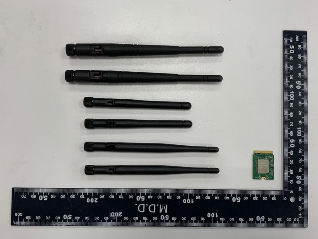
RYK-WNFB265AXIBT
Feb 23, 2021IEEE 802.11ax/ac/a/b/g/n 2x2 WiFi with Bluetooth5.0 Combo Module
Equipment Class
NII - Unlicensed National Information Infrastructure TX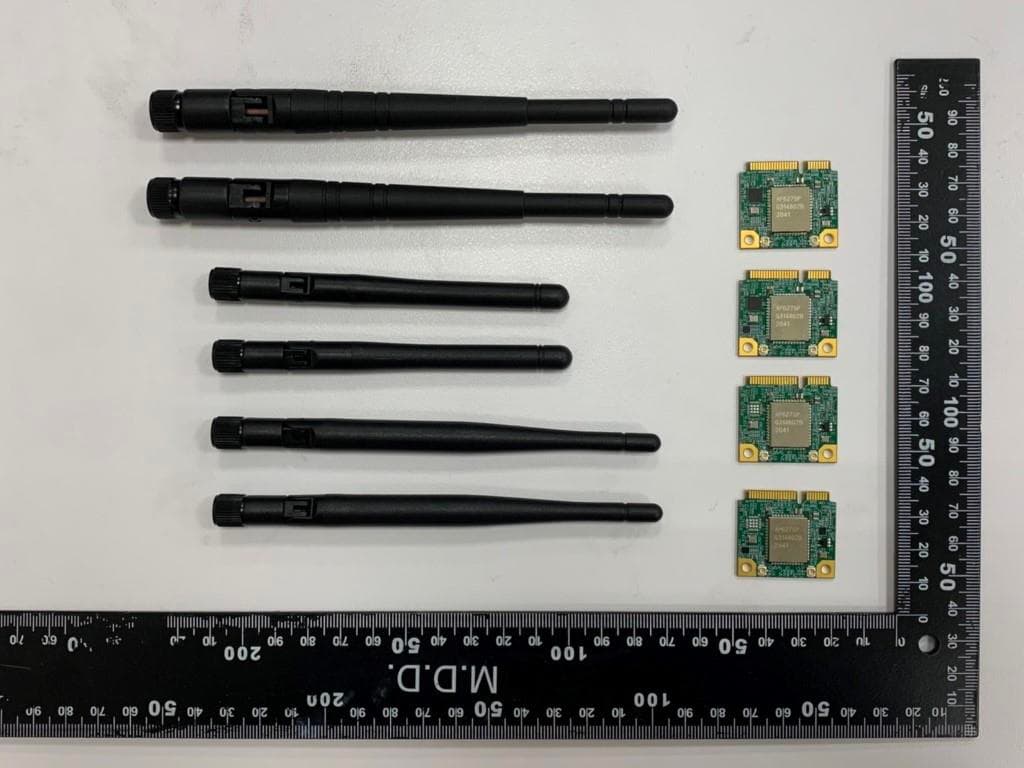
RYK-WPEB265AXIBT
Jan 10, 2021IEEE 802.11ax/ac/a/b/g/n 2x2 WiFi with Bluetooth5.0 Combo Module
Equipment Class
JBP - Part 15 Class B Computing Device Peripheral