RYK-WUBM273ACN802.11ac/b/g/n USB module
SparkLAN Communications, Inc.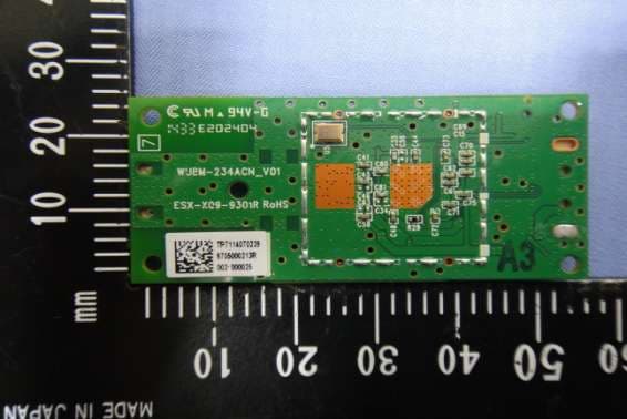
Click to zoom
Application Details
- Equipment Class
- NII - Unlicensed National Information Infrastructure TX
- Date of Grant
- Feb 07, 2015
- Application Purpose
- Original Equipment
- Date of Application
- Feb 07, 2015
- Equipment Note
- 802.11ac/b/g/n USB module
- Frequency Range
- 5775.00000000 - 5775.00000000
- Country
- Taiwan
Documents & Files
Document Text
Text extracted from the exhibit documents filed with the FCC. Open a document above to read the original.
Users Manual
WUBM-273 ACN Standard 802.11ac/b/g/n Chipset Mac/BB/RF MediaTek MT7612U Host Interface USB Type A or 12-pin wafer connector Form Factor USB Module Data Rates 802.11a: 6~54Mbps / 802.11b: 1~11Mbps / 802.11g: 6~54Mbps 802.11n: MCS0 ~ MCS15 / 802.11ac: MCS0 ~ MCS9 Radio Antenna 2 x U.FL connectors or printed antenna, 2T2R Operating Frequency ac/n ISM Band: 5.150GHz ~ 5.850GHz b/g/n ISM Band: 2.400GHz ~ 2.4835GHz *subject to local regulations Modulation 802.11a: OFDM (BPSK, QPSK,16-QAM, 64-QAM) 802.11b: DSSS (DBPSK, DQPSK, CCK) 802.11g: OFDM (BPSK, QPSK,16-QAM, 64-QAM) 802.11n: OFDM (BPSK, QPSK,16-QAM, 64-QAM) 802.11ac: OFDM (BPSK, QPSK,16-QAM, 64-QAM, 256-QAM) Output Power 802.11b: 15dBm ± 2dBm@11Mbps 802.11a: 12dBm ± 2dBm@54Mbps / 802.11g: 13dBm ± 2dBm@54Mbps 802.11gn (HT20): 12dBm ± 2dBm@MCS7 / 802.11gn (HT40): 12dBm ± 2dBm@MCS7 802.11an (HT20): 11dBm ± 2dBm@MCS7 / 802.11an (HT40): 11dBm ± 2dBm@MCS7 802.11ac (VHT80): 10dBm ± 2dBm@MCS9 Receive Sensitivity 802.11b: ≤ -76dBm@11Mbps 802.11a: ≤ -65dBm@54Mbps / 802.11g: ≤ -65dBm@54Mbps 802.11gn (HT20): ≤ -64dBm@MCS7 / 802.11gn (HT40): ≤ -61dBm@MCS7 802.11an (HT20): ≤ -64dBm@MCS7 / 802.11an (HT40): ≤ -61dBm@MCS7 802.11ac (VHT80): ≤ -51dBm@MCS9 Operating Voltage DC 5V /0.9A Environmental Temperature Range 0 ~ 40°C (Operating) / -10 ~ 70°C (Storing) Humidity (Non-Condensing) 10% ~ 85% (Operating) / 5% ~ 90% (Storing) Physical Specification Dimensions 55mm x 25mm x 3.3mm (± 0.5mm) Weight ≤ 7g Software Driver Windows XP/ Vista, Win 7, Win 8, Linux , Android by request Security WEP, WPA, WPA2, 802.1x This device complies with Part 15 of the FCC Rules. Operation is subject to the following two conditions: (1) this device may not cause harmful interference and (2) this device must accept any interference received, including interference that may cause undesired operation. This equipment has been tested and found to comply with the limits for a Class B digital device, pursuant to part 15 o f the FCC rules. These limits are designed to provide reasonable protection against harmful interference in a residentia l installation. This equipment generates, uses and can radiate radio frequency energy and, if not installed and used in accordance with the instructions, may cause harmful interference to radio communications. However, there is no guar antee that interference will not occur in a particular installation. If this equipment does cause harmful interference to r adio or television reception, which can be determined by turning the equipment off and on, the user is encouraged to try to correct the interference by one or more of the following measures: ‐Reorient or relocate the receiving antenna. ‐ Increase the separation between the equipment and receiver. ‐ Connect the equipment into an outlet on a circuit different from that to which the receiver is connected. ‐ Consult the dealer or an experienced radio/TV technician for help. You are cautioned that changes or modifications not expressly approved by the party responsible for compliance could void your authority to operate the equipment. FCC RF Radiation Exposure Statement: 1. This Transmitter must not be co‐ located or operating in conjunction with any other antenna or transmitter. 2. This equipment complies with FCC RF radiation exposure limits set forth for an uncontrolled environment. This equipm ent should be installed and operated with a minimum distance of 20 centimeters between the radiator and your body. According to FCC 15.407(e), the device is intended to operate in the frequency band of 5.15GHz to 5.25GHz under all conditions of normal operation. Normal operation of this device is restricted to indoor used only to reduce any potenti al for harmful interference to co‐channel MSS operations. Information to OEM integrator The OEM integrator has to be aware not to provide information to the end user regarding how to install or remove thi s RF module in the user manual of the end product. The user manual which is provided by OEM integrators for end us ers must include the following information in a prominent location. 1. To comply with IC RF exposure compliance requirements, the antenna used for this transmitter must be installed to provide a separation distance of at least 20 cm from all persons and must not be co-located or operating in conjunction with any other antenna or transmitter, except in accordance with IC multi‐transmitter product transmitter product procedures. 2. Only those antennas with same type and lesser gain filed under this IC ID number can be used with this device. 3. The regulatory label on the final system must include the statement: “Contains IC ID: xxxx “. 4. The final system integrator must ensure there is no instruction provided in the user manual or customer documenta tion indicating how to install or remove the transmitter module except such device has implemented two ways authentication between module and the host system. 5. If the end product integrating this module is going to be operated in 5.15 ~5.25GHz frequency range, the warning statement in the user manual of the end product should include the restriction of operating this device in indoor could void the user’s authority to operate the equipment.
Cover Letter(s)
Applicant/Grantee SparkLAN Communications, Inc FCC ID: RYK-WUBM273ACN Section 15.212 Modular Transmitters Request for Modular Approval Request for Limited Modular Approval Requirements EUT Conditions Comply (Y/N) Single Modular Approval Requirements 1 The radio elements of the modular transmitter must have their own shielding. The physical crystal and tuning capacitors may be located external to the shielded radio elements. The modular have RF own shielding Y 2 The modular transmitter must have buffered modulation/data inputs (if such inputs are provided) to ensure that the module will comply with Part 15 requirements under conditions of excessive data rates or over-modulation. The modular transmitter have buffered modulation/data inputs Y 3 The modular transmitter must have its own power supply regulation. The module contains its own power supply regulation. Please refer to the schematic. Y 4 The modular transmitter must comply with the antenna and transmission system requirements of Sections 15.203, 15.204(b) and 15.204(c). The antenna must either be permanently attached or employ a “unique” antenna coupler (at all connections between the module and the antenna, including the cable). The “professional installation” provision of Section 15.203 is not applicable to modules but can apply to limited modular approvals under paragraph (b) of this section. The modular must to built-in PIFA applicant together and transmission system requirements of Sections 15.203, 15.204(b) and 15.204(c). Y 5 The modular transmitter must be tested in a stand-alone configuration, i.e., the module must not be inside another device during testing for compliance with Part 15 requirements. Unless the transmitter module will be battery powered, it must comply with the AC line conducted requirements found in Section 15.207. AC or DC power lines and data input/output lines connected to the module must not contain ferrites, unless they will be marketed with the module (see Section 15.27(a)). The length of these lines shall be the length typical of actual use or, if that length is unknown, at least 10 centimeters to insure that there is no coupling between The EUT module can’t be operated by its own due to its power-less characteristic and hence needs external power supply to make it function. Under testing condition, no matter in pure verification or manufacturing stage, the specified test fixture must be provided to help testing the function and performance of the EUT sample. Y the case of the module and supporting equipment. Any accessories, peripherals, or support equipment connected to the module during testing shall be unmodified and commercially available (see Section 15.31(i)). 6 The modular transmitter must be equipped with either a permanently affixed label or must be capable of electronically displaying its FCC identification number. (A) If using a permanently affixed label, the modular transmitter must be labeled with its own FCC identification number, and, if the FCC identification number is not visible when the module is installed inside another device, then the outside of the device into which the module is installed must also display a label referring to the enclosed module. This exterior label can use wording such as the following: “Contains Transmitter Module FCC ID: XYZMODEL1” or “Contains FCC ID: XYZMODEL1.” Any similar wording that expresses the same meaning may be used. The Grantee may either provide such a label, an example of which must be included in the application for equipment authorization, or, must provide adequate instructions along with the module which explain this requirement. In the latter case, a copy of these instructions must be included in the application for equipment authorization. (B) If the modular transmitter uses an electronic display of the FCC identification number, the information must be readily accessible and visible on the modular transmitter or on the device in which it is installed. If the module is installed inside another device, then the outside of the device into which the module is installed must display a label referring to the enclosed module. This exterior label can use wording such as the following: “Contains FCC certified transmitter module(s).” Any similar wording that expresses the same meaning may be used. The user manual must include instructions on how to access the electronic display. A copy of these instructions must be included in the application for equipment authorization. The FCC identification number can put on the modular with either a permanently affixed label Y 7 The modular transmitter must comply with any specific rules or operating requirements that ordinarily apply to a complete transmitter and the manufacturer must provide adequate instructions along with the module to explain any such requirements. A copy of these instructions must be included in the The modular have specific rules or operating requirements Y
External Photos
Compliance Certification Services Inc. Report No.: T141216W02 Date of Issue: January 12, 2015 A1 - 1 / 12 Rev. 00 APPENDIX 1 - PHOTOGRAPHS OF EUT EXTERNAL PHOTOGRAPHS OF EUT For 12pin wafer connector + printed antenna Compliance Certification Services Inc. Report No.: T141216W02 Date of Issue: January 12, 2015 A1 - 2 / 12 Rev. 00 For 12pin wafer connector + dipole antenna Compliance Certification Services Inc. Report No.: T141216W02 Date of Issue: January 12, 2015 A1 - 3 Rev. 00 For USB 3.0 type A + printed antenna Compliance Certification Services Inc. Report No.: T141216W02 Date of Issue: January 12, 2015 A1 - 4 Rev. 00 For USB 3.0 type A + dipole antenna
Internal Photos
Compliance Certification Services Inc. Report No.: T141216W02 Date of Issue: January 12, 2015 A1 - 5 Rev. 00 INTERNAL PHOTOGRAPHS OF EUT For 12pin wafer connector + printed antenna Antenna Compliance Certification Services Inc. Report No.: T141216W02 Date of Issue: January 12, 2015 A1 - 6 Rev. 00 Compliance Certification Services Inc. Report No.: T141216W02 Date of Issue: January 12, 2015 A1 - 7 Rev. 00 For 12pin wafer connector + dipole antenna Compliance Certification Services Inc. Report No.: T141216W02 Date of Issue: January 12, 2015 A1 - 8 Rev. 00 Antenna Compliance Certification Services Inc. Report No.: T141216W02 Date of Issue: January 12, 2015 A1 - 9 Rev. 00 For USB 3.0 type A + printed antenna Antenna Compliance Certification Services Inc. Report No.: T141216W02 Date of Issue: January 12, 2015 A1 - 10 Rev. 00 Compliance Certification Services Inc. Report No.: T141216W02 Date of Issue: January 12, 2015 A1 - 11 Rev. 00 For USB 3.0 type A + dipole antenna Compliance Certification Services Inc. Report No.: T141216W02 Date of Issue: January 12, 2015 A1 - 12 Rev. 00 Antenna
RF Exposure Info
Compliance Certification Services Inc. Report No.: T141216W02-MF Date of Issue: January 12, 2015 Page 1 Rev.00 This report shall not be reproduced except in full, without the written approval of Compliance Certification Services. APPENDIX I RADIO FREQUENCY EXPOSURE LIMIT According to §15.247(i), systems operating under the provisions of this section shall be operated in a manner that ensures that the public is not exposed to radio frequency energy levels in excess of the Commission's guidelines. See § 1.1307(b)(1) of this chapter. EUT Specification EUT 802.11ac/b/g/n USB module Model WUBM-273ACN Frequency band (Operating) 802.11b/g/n HT20: 2.412GHz ~ 2.462GHz 802.11n HT40: 2.422GHz ~ 2.452GHz 802.11a: 5150 ~ 5250MHz / 5725 ~ 5850MHz 802.11 HT20: 5150 ~ 5250MHz / 5725 ~ 5850MHz 802.11 HT40: 5150 ~ 5250MHz / 5725 ~ 5850MHz 802.11ac HT80: 5170 ~ 5330 MHz / 5775 MHz Others Device category Portable (<20cm separation) Mobile (>20cm separation) Others Exposure classification Occupational/Controlled exposure (S = 5mW/cm 2 ) General Population/Uncontrolled exposure (S=1mW/cm 2 ) Antenna Specification 5GHz:SparkLAN / WUBM-273ACN Antenna Gain :1.68 dBi (Numeric gain:1.47) LCT / DFE_ACBSMA-BGP Antenna Gain :5.00 dBi (Numeric gain:3.16) 2.4GHz:SparkLAN / WUBM-273ACN Antenna Gain :0.23 dBi (Numeric gain:1.05) LCT / DFE_ACBSMA-BGP Antenna Gain :3.00 dBi (Numeric gain:2.00) Maximum Average output power IEEE 802.11b Mode: 22.10 dBm(162.181 mW) IEEE 802.11g Mode: 14.95 dBm(31.261 mW) IEEE 802.11n HT 20 Mode: 19.21 dBm(83.368 mW) IEEE 802.11n HT 40 Mode: 14.96 dBm(31.333 mW) IEEE 802.11a Mode: 20.62 dBm(115.345 mW) IEEE 802.11n HT20 Mode: 22.10 dBm(162.181 mW) IEEE 802.11n HT40 Mode: 18.77 dBm(75.336 mW) IEEE 802.11ac HT80 Mode: 17.32 dBm(53.951 mW) Compliance Certification Services Inc. Report No.: T141216W02-MF Date of Issue: January 12, 2015 Page 2 Rev.00 This report shall not be reproduced except in full, without the written approval of Compliance Certification Services. Maximum Tune up Power IEEE 802.11b Mode: 24.00 dBm(251.189 mW) IEEE 802.11g Mode: 16.00 dBm(39.811 mW) IEEE 802.11n HT 20 Mode: 21.00 dBm(125.893 mW) IEEE 802.11n HT 40 Mode: 16.50 dBm(44.668 mW) IEEE 802.11a Mode: 21.50 dBm(141.254 mW) IEEE 802.11n HT20 Mode: 23.00 dBm(199.526 mW) IEEE 802.11n HT40 Mode: 20.00 dBm(100.000 mW) IEEE 802.11ac HT80 Mode: 19.00 dBm(79.433 mW) Evaluation applied MPE Evaluation* SAR Evaluation N/A Compliance Certification Services Inc. Report No.: T141216W02-MF Date of Issue: January 12, 2015 Page 3 Rev.00 This report shall not be reproduced except in full, without the written approval of Compliance Certification Services. Revision History Rev. Issue Date Revisions Effect Page Revised By 00 2015/01/07 Initial Issue ALL Kelly Cheng Compliance Certification Services Inc. Report No.: T141216W02-MF Date of Issue: January 12, 2015 Page 4 Rev.00 This report shall not be reproduced except in full, without the written approval of Compliance Certification Services. TEST RESULTS No non-compliance noted. Calculation Given d GP E 30 & 377 2 E S Where E = Field strength in Volts / meter P = Power in Watts G = Numeric antenna gain d = Distance in meters S = Power density in milliwatts / square centimeter Combining equations and re-arranging the terms to express the distance as a function of the remaining variables yields: 2 377 30 d GP S Changing to units of mW and cm, using: P (mW) = P (W) / 1000 and d (cm) = d(m) / 100 Yields 22 0796.0 100/377 1000/30 d GP d GP S Equation 1 Where d = Distance in cm P = Power in mW G = Numeric antenna gain S = Power density in mW / cm 2 Compliance Certification Services Inc. Report No.: T141216W02-MF Date of Issue: January 12, 2015 Page 5 Rev.00 This report shall not be reproduced except in full, without the written approval of Compliance Certification Services. Maximum Permissible Exposure Substituting the MPE safe distance using d = 20 cm into Equation 1: GPS000199.0 Where P = Power in mW G = Numeric antenna gain S = Power density in mW / cm 2 IEEE 802.11b mode: Ch.Frq.(MHz)P (mW)Gain (num.)D (cm) Power density in mW / cm 2 Limit (mW/cm2) 62437251.1892200.10001 IEEE 802.11g mode: Ch.Frq.(MHz)P (mW)Gain (num.)D (cm) Power density in mW / cm 2 Limit (mW/cm2) 6243739.8112200.01581 IEEE 802.11n HT20 mode: Ch.Frq.(MHz)P (mW)Gain (num.)D (cm) Power density in mW / cm 2 Limit (mW/cm2) 12412125.8932200.05011 IEEE 802.11n HT40 mode: Ch.Frq.(MHz)P (mW)Gain (num.)D (cm) Power density in mW / cm 2 Limit (mW/cm2) 6243744.6682200.01781 IEEE 802.11a mode: Ch.Frq.(MHz)P (mW)Gain (num.)D (cm) Power density in mW / cm 2 Limit (mW/cm2) 1655825141.2543.16200.08881 IEEE 802.11a HT20 mode: Ch.Frq.(MHz)P (mW)Gain (num.)D (cm) Power density in mW / cm 2 Limit (mW/cm2) 1655825199.5263.16200.12551 IEEE 802.11a HT40 mode: Ch.Frq.(MHz)P (mW)Gain (num.)D (cm) Power density in mW / cm 2 Limit (mW/cm2) 4652301003.16200.06291 IEEE 802.11ac HT80 Mode Ch.Frq.(MHz)P (mW)Gain (num.)D (cm) Power density in mW / cm 2 Limit (mW/cm2) 155577579.4333.16200.05001
Test Report
Compliance Certification Services Inc. FCC ID: RYK-WUBM273ACN Report No.: T141216W02-RP2 Note: This report shall not be reproduced except in full, without the written approval of Compliance Certification Services Inc. This document may be altered or revised by Compliance Certification Services Inc. personnel only, and shall be noted in the revision section of the document. Page 1 / 132 Rev.00 FCC 47 CFR PART 15 SUBPART E TEST REPORT For 802.11ac/b/g/n USB module Model: WUBM-273ACN Trade Name: SparkLAN Issued to SparkLAN Communications, Inc 8F., No.257, Sec. 2, Tiding Blvd., Neihu District, Taipei City 11493, Taiwan. Issued by Compliance Certification Services Inc. No.11, Wugong 6th Rd., Wugu Dist., New Taipei City 24891, Taiwan. (R.O.C.) http://www.ccsrf.com [email protected] Issued Date: January 7, 2015 Compliance Certification Services Inc. FCC ID: RYK-WUBM273ACN Report No.: T141216W02-RP2 Page 2 Rev.00 Revision History Rev. Issue Date Revisions Effect Page Revised By 00 January 7, 2015 Initial Issue ALL Kelly Cheng Compliance Certification Services Inc. FCC ID: RYK-WUBM273ACN Report No.: T141216W02-RP2 Page 3 Rev.00 TABLE OF CONTENTS 1. TEST RESULT CERTIFICATION ............................................................................................. 4 2. EUT DESCRIPTION .................................................................................................................... 5 3. TEST METHODOLOGY ............................................................................................................. 7 3.1 EUT CONFIGURATION ........................................................................................... 7 3.2 EUT EXERCISE ........................................................................................................ 7 3.3 GENERAL TEST PROCEDURES ............................................................................ 7 3.4 FCC PART 15.205 RESTRICTED BANDS OF OPERATIONS .............................. 8 3.5 DESCRIPTION OF TEST MODES........................................................................... 9 4. INSTRUMENT CALIBRATION ............................................................................................... 10 4.1 MEASURING INSTRUMENT CALIBRATION.................................................... 10 4.2 MEASUREMENT EQUIPMENT USED ................................................................ 10 4.3 MEASUREMENT UNCERTAINTY ...................................................................... 11 5. FACILITIES AND ACCREDITATIONS ................................................................................. 12 5.1 FACILITIES ............................................................................................................. 12 5.2 EQUIPMENT ........................................................................................................... 12 5.3 TABLE OF ACCREDITATIONS AND LISTINGS ............................................... 13 6. SETUP OF EQUIPMENT UNDER TEST ................................................................................ 14 6.1 SETUP CONFIGURATION OF EUT ..................................................................... 14 6.2 SUPPORT EQUIPMENT......................................................................................... 14 7. FCC PART 15 REQUIREMENTS............................................................................................. 15 7.1 26 DB EMISSION BANDWIDTH .......................................................................... 15 7.2 AVERAGE POWER ................................................................................................ 33 7.3 BAND EDGES MEASUREMENT.......................................................................... 36 7.4 PEAK POWER SPECTRAL DENSITY .................................................................. 53 7.5 RADIATED UNDESIRABLE EMISSION ............................................................. 71 7.6 POWERLINE CONDUCTED EMISSIONS ......................................................... 113 7.7 FREQUENCY STABILITY ................................................................................... 118 APPENDIX I PHOTOGRAPHS OF TEST SETUP ..................................................................... 128 Compliance Certification Services Inc. FCC ID: RYK-WUBM273ACN Report No.: T141216W02-RP2 Page 4 Rev.00 1. TEST RESULT CERTIFICATION Applicant: SparkLAN Communications, Inc 8F, No.150, Jian Yi Rd, Zhonghe District, New Taipei City, 235, Taiwan Equipment Under Test: 802.11ac/b/g/n USB module Trade Name: SparkLAN Model: WUBM-273ACN Date of Test: December 27, 2014 ~ January 5, 2015 APPLICABLE STANDARDS STANDARD TEST RESULT FCC 47 CFR Part 15 Subpart E No non-compliance noted We hereby certify that: Compliance Certification Services Inc. tested the above equipment. The test data, data evaluation, test procedures, and equipment configurations shown in this report were made in accordance with the procedures given in ANSI C63.4: 2009 and the energy emitted by the sample EUT tested as described in this report is in compliance with conducted and radiated emission limits of FCC Rules Part 15.407. The test results of this report relate only to the tested sample identified in this report. Approved by: Reviewed by: Miller Lee Angel Cheng Section Manager Section Manager Compliance Certification Services Inc. Compliance Certification Services Inc. Compliance Certification Services Inc. FCC ID: RYK-WUBM273ACN Report No.: T141216W02-RP2 Page 5 Rev.00 2. EUT DESCRIPTION Product 802.11ac/b/g/n USB module Trade Name SparkLAN Model Number WUBM-273ACN Model Discrepancy N/A Received Date December 16, 2014 Power Supply Powered from host device Operating Frequency Range & Number of Channels Mode Frequency Range (MHz) Number of Channels UNII Band I IEEE 802.11a 5180 – 5240 4 Channels IEEE 802.11n HT 20 mode 5180 – 5240 4 Channels IEEE 802.11n HT 40 mode 5190 – 5230 2 Channels IEEE 802.11ac80 mode 5210 1 Channels UNII Ban…
Text truncated - open the document above for the full version.
Test Setup Photos
Compliance Certification Services Inc. FCC ID: RYK-WUBM273ACN Report No.: T141216W02-RP2 Page 134 Rev.00 APPENDIX I PHOTOGRAPHS OF TEST SETUP CONDUCTED EMISSION SET UP PHOTO Compliance Certification Services Inc. FCC ID: RYK-WUBM273ACN Report No.: T141216W02-RP2 Page 135 Rev.00 RADIATED EMISSION SET UP PHOTOS For printed Antenna Compliance Certification Services Inc. FCC ID: RYK-WUBM273ACN Report No.: T141216W02-RP2 Page 136 Rev.00 For Dipole Antenna Compliance Certification Services Inc. FCC ID: RYK-WUBM273ACN Report No.: T141216W02-RP2 Page 137 Rev.00 POWERLINE CONDUCTED EMISSIONS SETUP PHOTOS For printed Antenna Compliance Certification Services Inc. FCC ID: RYK-WUBM273ACN Report No.: T141216W02-RP2 Page 138 Rev.00 For Dipole Antenna
Contact Information
Applicant
Grady Lin(Manager)
Test Firm
Compliance Certification Services Inc.Hank Lee
Technical Specifications
| # | Rule Parts | Frequency Range | Power Output |
|---|---|---|---|
| 6 | 15E | 5.78 GHz - 5.78 GHz | 54.00 mW |
Other Applications from SparkLAN Communications, Inc.
RYK-AP6275SDSR
Jan 11, 2023IEEE 802.11ax/ac/a/b/g/n 2x2 WiFi with Bluetooth5.2 M.2 LGA Type 1216 Module
Equipment Class
DTS - Digital Transmission System
RYK-WPEQ268AXBT
Dec 01, 2022Wi-Fi 6E BT Half Min PCIe Module
Equipment Class
DTS - Digital Transmission System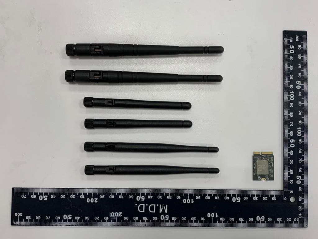
RYK-WNFB266AXIBT
Mar 20, 2021IEEE 802.11ax/ac/a/b/g/n 2x2 WiFi with Bluetooth5.0 Combo Module
Equipment Class
NII - Unlicensed National Information Infrastructure TX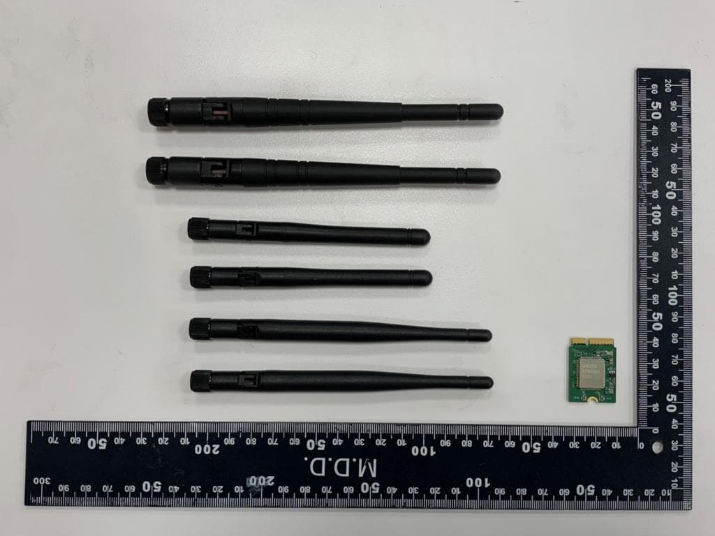
RYK-WNFB265AXIBT
Feb 23, 2021IEEE 802.11ax/ac/a/b/g/n 2x2 WiFi with Bluetooth5.0 Combo Module
Equipment Class
NII - Unlicensed National Information Infrastructure TX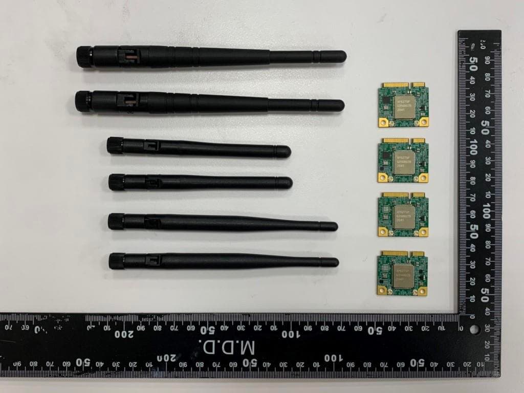
RYK-WPEB265AXIBT
Jan 10, 2021IEEE 802.11ax/ac/a/b/g/n 2x2 WiFi with Bluetooth5.0 Combo Module
Equipment Class
JBP - Part 15 Class B Computing Device Peripheral