S2Y-MINISDW11BGMini SDIO Wireless 11b/g
Spectec Computer Co., Ltd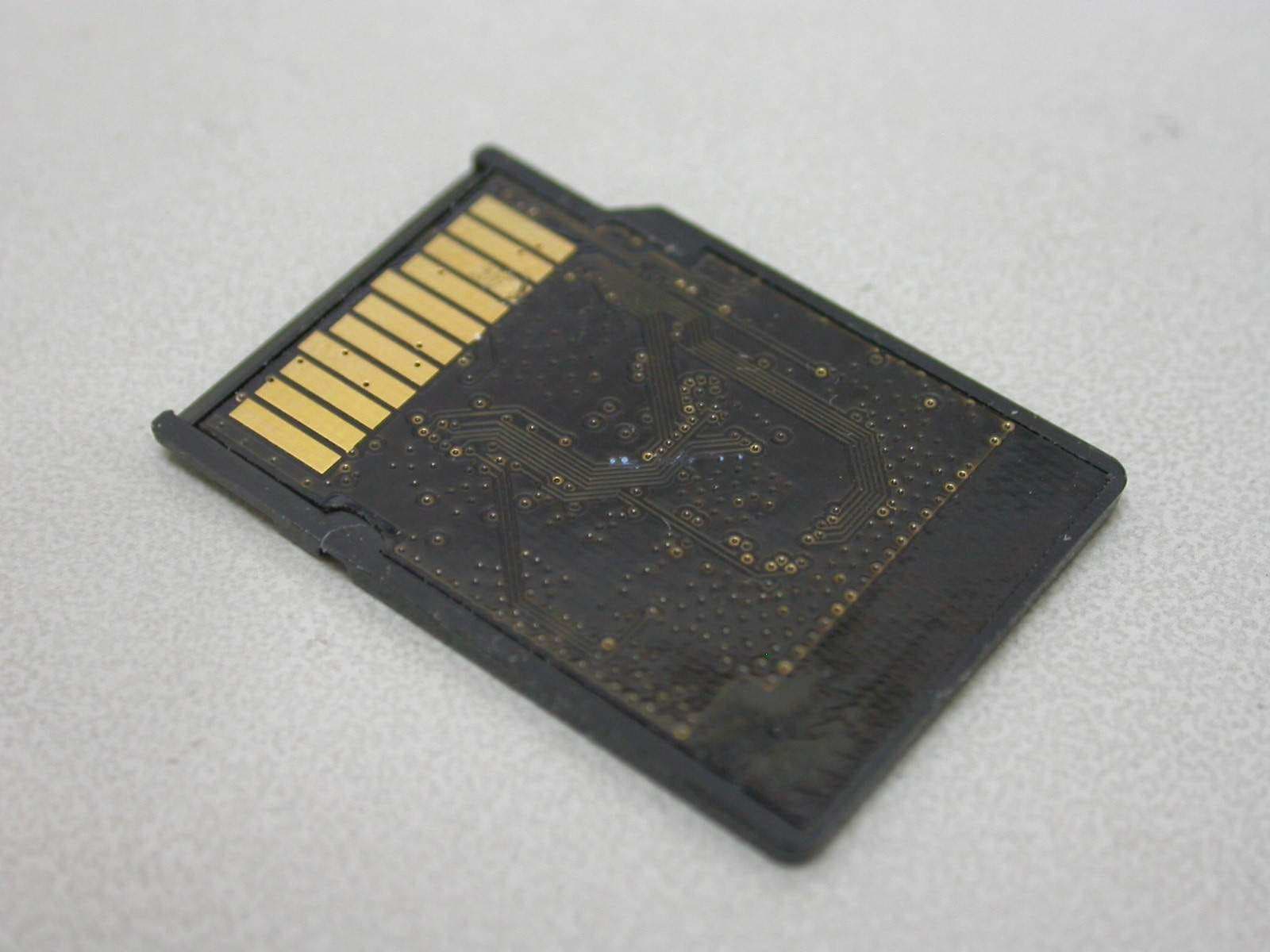
Click to zoom
Application Details
- Equipment Class
- DTS - Digital Transmission System
- Date of Grant
- Jul 01, 2007
- Application Purpose
- Original Equipment
- Date of Application
- Jul 01, 2007
- Equipment Note
- Mini SDIO Wireless 11b/g
- Frequency Range
- 2412.00000000 - 2462.00000000
- Company
- Spectec Computer Co., Ltd
- Country
- Taiwan
Documents & Files
Document Text
Text extracted from the exhibit documents filed with the FCC. Open a document above to read the original.
Users Manual
1b TM Wireless/Internet SDIO WLAN card SDIO WLAN Card User’s Manual ver. 1.40 1b TM TM WLAN-1 1b 802.1 1b TM www.spectec.com.t w Wireless/Internet SDIO WLAN card TM WLAN-11b 0012E6000506 FCC ID:S2YMINIWLAN 11 B W L A N - 1 1 b / g S D I O W L A N C a r d w w w.s p e c t e c.c o m . t w Content Inside Package ................................................................................................P.1 System Requirements & Installation Description...........................................P.1 Installation Procedure .................................................................................P.2~5 Inserting the SDIO WLAN Card into a PDA .................................................P.6 Removing the SDIO WLAN Card from a PDA ............................................P.6 How to check Connect status ........................................................................P.7~8 How to Connect Ad-hoc..............................................................................P.9 How to Remove Settings...............................................................................P.9 Wireless/Internet Speed Dial ........................................................................P.10~11 How to Select Networks Manually ...............................................................P.12 Inside CD ........................................................................................................P.13 How to Install Software with CAB file............................................................P.14 AP Compatibility List ......................................................................................P.15 Frequently Ask Question ...............................................................................P.16 1 Thank you for choosing SDIO WLAN card, it is the smallest SDIO Wireless/Internet WLAN card available on the market today. It is easy to install and use, and pro - vides unlimited online usage and connectivity wherever you are. Inside Package System Requirements & Installation Description 1. This SPECTEC SDIO Wi-Fi card can only be used in Pocket PCs with Windows Mobile 2003 or newer versions of this operation system. 2. This SPECTEC SDIO Wi-Fi card can only be used on PDAs with the SDIO drive. Driver & User Guide CD WLAN-1 1b 802.1 1b TM www.spectec.com.t w WLAN-11b 0012E6000506 FCC ID:S2YMINIWLAN 11 B W L A N - 1 1 b / g S D I O W L A N C a r d w w w.s p e c t e c.c o m . t w SDW-820 SDW-82 1 SDW-82 2 SDW-82 3 SDW-825 2 Installation Procedure < First, connect PDA to your computer with a USB wire. < Main menu window will pop-up when you insert the "Spectec SDIO Series" Installation CD by autorun: <click the Moto Q GSM 802.11b/g WLAN Card item for SDW-825. 3 < Choose the desired Language, then click OK. < The Installation menu will automatically appear on the screen. < Click Next 1 2 3 4 4 5 6 7 8 < Enter user information, then click Next. < Chose Setup type, then click Next 5 < The driver will be installed automatically. < Click Yes to proceed with installation. Click OK to finish installation. < Click Finish to complete the driver installation process. 10 11 9 WLAN-11b 802.1 1b TM www.spectec.com.tw WLAN-11b 0012E6000506 FCC ID:S2YMINIWLAN 11 B 6 How to take a SDIO WLAN card out of a PDA < Check the direction of the card. Insert the card with the label side facing the front of the PDA until it clicks. # Different PDAs may have different drives. Make sure the direction is correct to avoid damaging the PDA’s SD drive. < When removing the SDIO WLAN card from a PDA, simply press down on the card until it clicks. The card will rise up for easy removal. DO NOT PULL by force, or the slot may be damaged. < This card is designed to be locked into the slot. Forcefully pulling the card out will not only damage this auto pop-out function, but also the slot and the wireless card. Pull out Card rises, then pull out Press down Inserting the SDIO WLAN Card into a PDA * Please do not ke ep inserting & removing the card , different PDA s needs an interval of 5 to 7 seconds to process. 1 2 1 2 B WLAN-1 1b 802.1 1b TM www.spectec.com.t w WLAN-1 1b 802.1 1b TM www.spectec.com.t w WLAN-11b 0012E6000506 FCC ID:S2YMINIWLAN 11 B WLAN-1 1b 802.1 1b TM www.spectec.com.t w WLAN-1 1b 802.1 1b TM www.spectec.com.t w 7 How to check Connect Status < After install the software, start path as Start\Programs. < After inserting the card into the PDA, click Start. Click Programs on the pull-down menu, then select .(Only built-in 11b card for PCC2003) < Click to open the WLAN Utility window. 2 WLAN-11b 802.1 1b TM www.spectec.com.tw 8 In “Radio” page of WLAN Utility, you may check S/W Radio Off/on for Enable/ Disable Wi-Fi card, or you can also find a shortcut icon at the lower right hand corner of the screen. < Click , shortcut icon to switch on/off Wi-Fi radio * Note : The WLAN Utility can be only compatibility on PPC 2003(CE4.X) and few windows mobile 5.0(CE5.0) OS 9 How to Connect Ad-hoc 1. In WLAN Utility, select Ad-Hoc Channel (must be channel 1). 2. Click OK to exit WLAN Utility. 3. Remove the card from PDA, then re-insert the card. 4. Go to PDA system: Settings\Connections\ Network Cards. 5. Click Add New. 6. Type in the name (ex. aa). 7. Check the “This is a device-to-device (ad-hoc) connection” box. 8. Click OK. The input name (ex. aa) will be added to the Network Address. *Ad-hoc channel is a “Point-to-point” network segment. It provides you with a temporary LAN environment. In Settings, select the network name that you would like to remove. Wait 2 seconds for the ‘Remove Settings’ pop-up window to appear. How to Remove Settings 1 PS: Channe 12 is the channel in America 2 4 5 6 7 8 3 WLAN-11b 802.1 1b TM www.spectec.com.tw
Users Manual
10 Wireless/Internet Speed Dial < Click 1. Make quick changes to the wireless card On/Off function. 2. “Open” to go directly to WLAN Utility screen for more information. WLAN Utility has 3 features (Status/Radio/About): *Status - Shows SSID, IP Address, Mac Address, Signal Strength, and Signal Quality information. *Radio - Enable/Disable Wi-Fi card and Power Saving mode selections. < Click On enables wireless network functions. < Click Off disables wireless network functions. < Ad Hoc Channel: Select ad hoc channels (1~11). Power Saving: < Disable: No power saving. < Enable (Max): Maximum power saving. May affect download speed. < Enable (Fast): No affect on the download speed (recommend). 11 *About -- Shows SPECTEC connections info. < Driver: Current version of driver you installed. < Utility: Current version of utility you installed. < SPECTEC Web Site: http//:www.spectec.com.tw < Technical Support: [email protected] WLAN-1 1b 802.1 1b TM www.spectec.com.t w 12 < From Start Menu/Settings/ Connections/Network Cards, select icon for a pull-down menu. Click Settings to go into the Settings/Connections window. < Click and hold Connect for 2 seconds, then click OK. All available network selections will appear. To Select Networks Manually After inserting SDIO WLAN card into PDA, if the icon does not appear on the upper window, the network may be connected manually. WLAN-11 b 802. 11 b TM www .spectec.com.tw 1 13 CD info < Click Browse Contents button to review all the files on CD < Review all the files list on CD 14 1. Driver and Utility (cab file) Take out the WLAN card, click “reset”, connect computer thr ough Microsoft Active Sync , download Driver cab file copy to any list of PDA, double-click it to finish install. 2. User Manul download (Adobe PDF) Please go to the addreess - http://www.adobe.com/ products/acrobat/readstep2.html to download free Adobe Reader software How to Install Software with CAB File WLAN-11b 802.1 1b TM www.spectec.com.tw 15 AP Compatibility List Test condition and test environment DUT: WLAN-11b * Measurements: mbps RX: Receiver TX: Sender * Test Environment : Night without Raining C ~ 32 C Distance from 5m ~ 30m * Collect data tool : Windows CE Platform Builder 5.0 performance monitor tool Vendor Acct on ASUS At hero s BENQ BE LK IN Bu ff alo Model IG 2004W WL -500b WL -530g AR5002AP AW L700 F5D7230 AG 54 WLA- L11G -L Rate TX RX TX RX TX RX TX RX TX RX TX RX TX RX TX RX Auto Rate 1.55 2.62 1.71 2.88 1.49 2.43 1.61 2.84 1.67 2.39 1.59 2.43 1.61 2.82 1.66 2.90 Vendor Cisco Corega DLink Ge mt ek Interepoch Intersil Li nk sy s Model AP 1220 WL BA RG P DLink624 DLink724 WX- 1500 series IWE- 1100A ISL 39300 WR K 54G Rate TX RX TX RX TX RX TX RX TX RX TX RX TX RX TX RX Auto Rate 1.67 2.87 1.67 2.67 1.63 2.80 1.63 2.80 1.61 2.44 1.60 2.44 1.70 2.91 1.64 2.78 Vendor Maxi m OriNoCo PC I Prox im RA YT AC SMC 3Com Model WA P- G5 4A AP -200 BL W- 04gm AP 600 DS2400 WBR 14 -G XJ AC K AP 2000 Rate TX RX TX RX TX RX TX RX TX RX TX RX TX RX TX RX Auto Rate 1.63 2.89 1.56 2.73 1.63 2.80 1.63 2.79 1.64 2.67 1.67 2.43 1.60 2.78 1.68 2.78 Vendor Synnex MSI AboCom SENAO ZERO ONE Model LM -WCAS3040 RG54G2 WB1 04 k NL-2511SR+ AF411W Rate TX RX TX RX TX RX TX RX TX RX Auto Rate 1.59 2.77 1.60 2.65 1.69 2.87 1.66 2.49 1.54 2.69 16 Frequently Ask Question Q: After installing the CD-ROM, how many files will be installed onto the device? A: After installation, some dll files are installed in My Device\Windows, and the WLAN Utility in Programs. However, these files are quite small, and total about 300 KB. Q: How do I temporarily stop the wireless/internet connection? A: You can click on the “Off” button in WLAN Utility. When all 5 blue bars are white, Wi-Fi is disabled. Selecting the “On” setting will reconnect you to the internet. Q: What do the 5 bars from “WLAN Utility” indicate? A: These 5 bars show the strength of the signals. More blue bars indicate stronger signals, while all white bars indicate no connection. Q: Why can’t I browse the web page even though the card has an IP address? A: When connecting to the internet with a weak signal, CRC may have too many errors to allow viewing a web page. Please try your connection around strong signals. Q: Can your Wi-Fi card be used for internet phone such as Skype? A: Yes, our Wi-Fi card can be used with Skype software. We suggest to use in an empty field, and with wired headphones for better results. 17 Warranty hank you for your purchase of our product. For Spectec’s quality service, please read the following for your rights. 1. Warranty period is 1 year, starting from the date of original purchase. Please provide original purchase receipt with purchase date when inquiring for service. 2. This product has passed all quality control and AP tests for quality assurance. We suggest to use it with the AP list, and other accepted industry-standard equipments. 3. If the damage is resulted from product design, defects in material or poor workmanship, we will repair or exchange your product. 4. This warranty does not cover failures resulted from accidents, misuse, abuse, neglect, mishandling, misapplication, alteration, faulty installation, improper maintenance, power line surge, lightning damage, modification, serviced by anyone other than an Authorized Servicer, or other natural causes. 5. This warranty does not cover failures caused by products not supplied by the warrantor. CAREFULLY READ THE FOLLOWING TERMS AND CONDITIONS BEFORE USING THIS PRODUCT. IT CONTAINS SOFTWARE, THE USE OF WHICHIS LICENSED BY SPECTEC, Co., Ltd., TO ITS CUSTOMERS FOR THEIR USE ONLY AS SET FORTH BELOW. IF YOU DO NOT AGREE TO THE TERMS AND CONDITIONS OF THIS AGREEMENT, DO NOT USE THE SOFTWARE. USING ANY PART OF THE SOFTWARE INDICATES THE ACCEPTANCE OF THESE TERMS. LICENSE: SPECTEC grants you a nonexclusive license to use the accompanying software program(s) (the “Software”) subject to the terms and restrictions set forth in this License Agreement. You are not permitted …
Text truncated - open the document above for the full version.
External Photos
ETC Report No.: 07-04-MAS-001-01 Page A1 of A1 FCC ID. :S2Y-MINISDW11BG ANNEX A: EXTERNAL CONSTRUCTION PHOTOS OF EUT 1. Outside view 1 of EUT 2. Outside view 2 of EUT
ID Label/Location Info
FCC ID Label & Location
Internal Photos
ETC Report No.: 07-04-MAS-001-01 Page B1 of B1 FCC ID. :S2Y-MINISDW11BG ANNEX B: INTERNAL CONSTRUCTION PHOTOS OF EUT 1. Front view of PCB 2. Rear view of PCB
Test Report
ETC Report No. : 07-04-MAS-001-01 Sheet 1 of 77 Sheets FCC ID. :S2Y-MINISDW11BG Rev. No 1.0 CONFORMANCE TEST REPORT FOR FCC 47 CFR, Part 15 Subpart C Report No.: 07-04-MAS-001-01 Client: Spectec Computer Co.,Ltd Product: Mini SDIO Wireless 11b/g Model: SDW-825 FCC ID: S2Y-MINISDW11BG Manufacturer/supplier: Spectec Computer Co.,Ltd Date test item received: 2007/04/03 Date test campaign completed: 2007/07/02 Date of issue: 2007/07/02 The test result only corresponds to the tested sample. It is not permitted to copy this report, in part or in full, without the permission of the test laboratory. Total number of pages of this test report: 77 pages Total number of pages of photos: External photos 1 pages Internal photos 1 pages Setup photos 3 pages Test Engineer Checked By Approved By Eric Lin James Joe Hsieh ELECTRONICS TESTING CENTER, TAIWAN NO.8, LANE 29, WENMING RD., LESHAN TSUEN, GUISHAN SHIANG, TAOYUAN COUNTY, TAIWAN 33383, R.O.C.TAIWAN, R.O.C. TEL: (03) 3276170~4 INT: +886-3-3276170~4 FAX: (03) 3276188 INT: +886-3-3276188 ETC Report No. : 07-04-MAS-001-01 Sheet 2 of 77 Sheets FCC ID. :S2Y-MINISDW11BG Rev. No 1.0 Client : Spectec Computer Co.,Ltd Address : 6F No.92 Nanking E. Rd. Sec.5 , Taipei , Taiwan , R.O.C Manufacturer : Spectec Computer Co.,Ltd Address : 6F No.92 Nanking E. Rd. Sec.5 , Taipei , Taiwan , R.O.C EUT : Mini SDIO Wireless 11b/g Trade name : Spectec Model No. : SDW-825 Power Source : 3.3V DC Regulations applied : FCC 47 CFR, Part 15 Subpart C (2006) The testing described in this report has been carried out to the best of our knowledge and ability, and our responsibility is limited to the exercise of reasonable care. This certification is not intended to believe the sellers from their legal and/or contractual obligations. The compliance test is only certified for the test equipment and the results of the testing report relate only to the item tested. The compliance test of this report was conducted in accordance with the appropriate standards. It’s not intention to assure the quality and performance of the product. This report shall not be reproduced except in full, without the approval of ETC. This report must not be used by the client to claim product endorsement by NVLAP or any agency of the U.S. Government. Laboratory Introduction: Electronics Testing Center, Taiwan is recognized, filed and mutual recognition arrangement as following: 1 ISO9001: TüV Product Service 2 ISO/IEC 17025: BSMI, CNLA, DGT, NVLAP, CCIBLAC, UL, Compliance 3 Filing: FCC, Industry Canada, VCCI 4 MRA: Australia, Hong Kong, New Zealand, Singapore, USA, Japan, Korea, China, APLAC through CNLA 5 FCC Registration Number: 90588, 91094, 91095 NVLAP Lab Code 200133-0 ETC Report No. : 07-04-MAS-001-01 Sheet 3 of 77 Sheets FCC ID. :S2Y-MINISDW11BG Rev. No 1.0 Table of Contents Page 1 GENERAL INFORMATION ............................................................................................................5 1.1 Product Description............................................................................................................................5 1.2 Characteristics of Device ...................................................................................................................5 1.3 Test Methodology ..............................................................................................................................5 1.4 Test Facility........................................................................................................................................5 2 PROVISIONS APPLICABLE ...........................................................................................................6 2.1 Definition ...........................................................................................................................................6 2.2 Requirement for Compliance .............................................................................................................7 2.3 Restricted Bands of Operation ...........................................................................................................9 2.4 Labeling Requirement........................................................................................................................9 2.5 User Information ..............................................................................................................................10 3. SYSTEM TEST CONFIGURATION .............................................................................................11 3.1 Devices for Tested System...............................................................................................................11 4 CONDUCTED EMISSION MEASUREMENT .............................................................................12 4.1 Standard Applicable.........................................................................................................................12 4.2 Measurement Procedure...................................................................................................................12 4.3 Conducted Emission Data................................................................................................................13 4.4 Result Data Calculation....................................................................................................................25 4.5 Conducted Measurement Equipment ...............................................................................................25 5 ANTENNA REQUIREMENT .........................................................................................................26 5.1 Standard Applicable.........................................................................................................................26 5.2 Antenna Construction and Directional Gain....................................................................................26 6 EMISSION BANDWIDTH MEASUREMENT .................................................…
Text truncated - open the document above for the full version.
Test Setup Photos
ETC Report No.:07-04-MAS-001-01 Sheet 1 of 3 Sheets FCC ID. :S2Y-MINISDW11BG Radiated Measurement Photos x-axis ETC Report No.:07-04-MAS-001-01 Sheet 2 of 3 Sheets FCC ID. :S2Y-MINISDW11BG y-axis z-axis ETC Report No.:07-04-MAS-001-01 Sheet 3 of 3 Sheets FCC ID. :S2Y-MINISDW11BG Photos of Conduction Measuring Setup
Contact Information
Applicant
S.T. Joung(General manager)
Test Firm
Electronics Testing Center, TaiwanWill Yauo
Technical Specifications
| # | Rule Parts | Frequency Range | Power Output |
|---|---|---|---|
| 1 | 15C | 2.41 GHz - 2.46 GHz | 13.34 mW |
Other Applications from Spectec Computer Co., Ltd
S2Y-SDWLAN11BGN
Dec 26, 2012SDW-829
Equipment Class
DTS - Digital Transmission System
S2Y-SDJ731ZD
Mar 18, 2012SDJ-731
Equipment Class
DTS - Digital Transmission System
S2Y-SDG812BTGPS
Jun 17, 2007SD BT GPS
Equipment Class
DSS - Part 15 Spread Spectrum Transmitter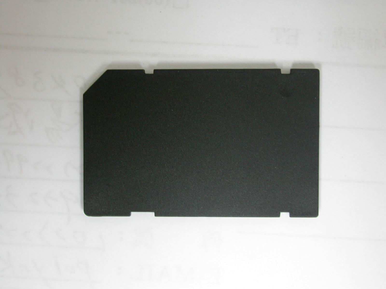
S2Y-WLAN-11B-G
Jan 29, 2006SDIO Wireless Lan Card
Equipment Class
DTS - Digital Transmission System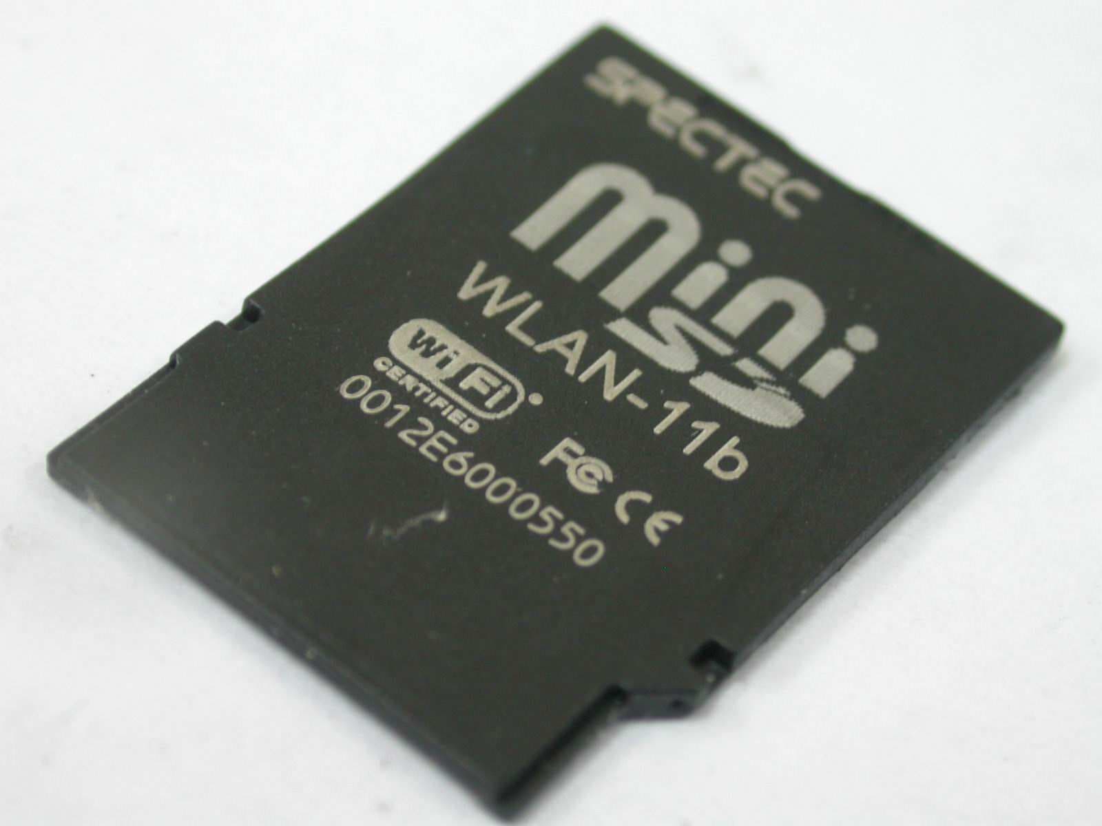
S2Y-MINIWLAN11B
Sep 07, 2005Mini SDIO Wireless LAN Card
Equipment Class
DTS - Digital Transmission System