S2Y-SDG812BTGPSSD BT GPS
Spectec Computer Co., Ltd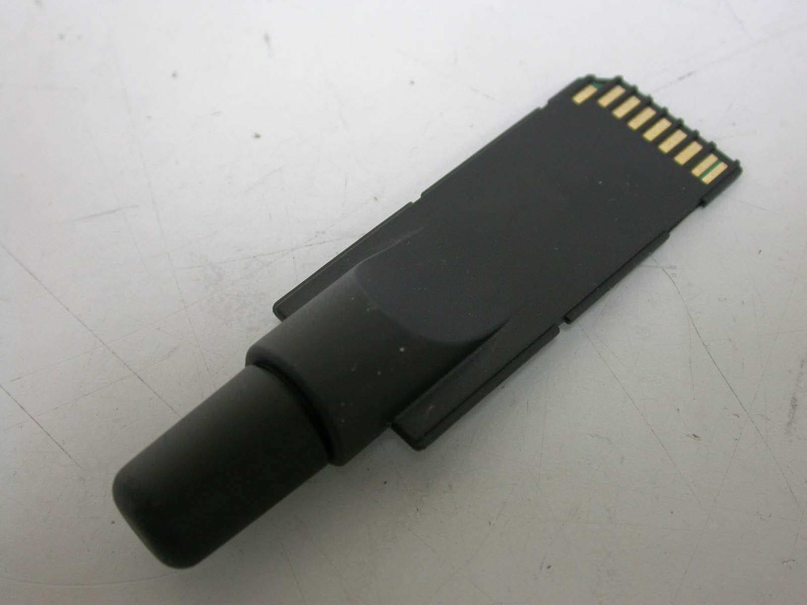
Click to zoom
Application Details
- Equipment Class
- DSS - Part 15 Spread Spectrum Transmitter
- Date of Grant
- Jun 17, 2007
- Application Purpose
- Original Equipment
- Date of Application
- Jun 14, 2007
- Equipment Note
- SD BT GPS
- Frequency Range
- 2402.00000000 - 2480.00000000
- Company
- Spectec Computer Co., Ltd
- Country
- Taiwan
Documents & Files
Document Text
Text extracted from the exhibit documents filed with the FCC. Open a document above to read the original.
Users Manual
1 CONTENT 1 Introduction ---------------------------------------------------------------------------- p2 1-1 Feature ----------------------------------------------------------------------------- p2 1-2 LED Function --------------------------------------------------------------------- p3 2 GPS Setting and pairing------------------------------------------------------------- p3~p6 3. SDG-812 Specification Table --------------------------------------------------------- p7 2 1 Introduction: SDG-812 is a GPS with Bluetooth interface and an integrated built-in memory, which provides an impressive data capacity. SDG-812 is not only a GPS receiver, but also a SD memory card. You can easily organize, store, and share files or documents. The dimension of SDG-812 is the smallest one in the market, you can easily bring it with your handheld device without occupying much space, and SDG-812 equipped with helix Antenna, you can complete the GPS fix in your car either at front seat or back seat easily. It also allow for tracking signals and large map data according to the mapping software usage. It’s sleek and stylish design of look can go with any kind of the Pocket PC. With the smallest dimension and light and handy appearance, it is convenient for you to put it in pocket and bring it to anywhere you go. Just plug it into your Pocket PC, and use it to receive the GPS signal right away! Its cylindrical antenna can receive the signal from all directions by 360 degree. It satisfies a wide variety of applications, including car navigation, personal touring navigation or tracking and even marine navigation purpose. With our professional manufacturing technology along with the cutting edge, SiRF Star III chipset, this receiver has provided higher sensitivity, lower power usage and much more rapid time-to-fix. 1-1 Feature .SiRF Star III high performance and low power consumption chipset .Built-in high sensitivity GPS antenna .LED to show GPS fix or not fix .Built-in super capacitor to receive system data for rapid satellite acquisition .Bluetooth interface .Operating platform: Windows CE , Windows mobile ,Windows XP, Symbian , Linux , Palm and Mac 1-2 LED Function GPS Status LED(Blue) .Blink --- GPS position is not fixed .Solid --- GPS position is fixed 3 2. GPS setting and pairing Install Free GPS utility Gps Viewer a. Open the Bluetooth funtion b. Running the GPS Viewer and click scan c. The Bluetooth will search and paring , Select SPECTEC SD-GPS when seach finish 4 d. key in the pin code “ 000000” ` e. The GPS comport will be found 5 f. Click Open GPS g. Select incoming device “ SPECTEC SD-GPS “ 6 h. Click GPS Status 7 NOTE: The changes or modifications not expressly approved by the party responsible for compliance could void the user’s authority to operate the equipment. To comply with the FCC RF exposure compliance requirements, this device and its antenna must not to be co-located or operating to conjunction with any other antenna or transmitter. FCC INFORMATION The Federal Communication Commission Radio Frequency Interference Statement includes the following paragraph: The equipment has been tested and found to comply with the limits for a Class B Digital Device, pursuant to part 15 of the FCC Rules. These limits are designed to pro- vide reasonable protection against harmful interference in a residential installation. This equipment generates, uses and can radiate radio frequency energy and, if not installed and used in accordance with the instruction, may cause harmful interference to radio communication. However, there is no grantee that interference will not occur in a particular installation. If this equipment dose cause harmful interference to radio or television reception, which can be determined by turning the equipment off and on, the user is encouraged to try to correct the interference by one or more of the follow- ing measures: --Reorient or relocate the receiving antenna. --Increase the separation between the equipment and receiver. --Connect the equipment into an outlet on a circuit different from that to which the receiver is connected. --Consult the dealer or an experienced radio/TV technician for help. This device complies with Part 15 of the FCC Rules. Operation is subject to the following two conditions: (1) this device may not cause harmful interference, and (2) this device must accept any interference received, including interference that may cause undersired operation. 8 3. SDG-812 Specification Table Electrical Characteristics (Receiver) Chipset SiRF Start III Frequency L1, 1575.42 MHz C/A Code 1.023 MHz chip rate Channels 20 channel all-in-view tracking Accuracy Position Horizontal 10 meters, 2D RMS 1~5 meters, 3D RMS with WAAS, EGNOS corrected Velocity 0.1m/sec Time 1 micro-second synchronized to GPS time Datum Datum WGS-84 (default) Protocol (customized protocol can be made if the offer is for more than 1000 pcs) GPS Protocol NMEA 0183 (default) GPS Output format GGA(1 sec), GSA(1 sec), GSV(5 sec), RMC, 9600bps Dynamic Condition Acceleration Limit Less than 4g Altitude Limit 18,000 meters (60,000 feet) max. Velocity Limit 515 meters/sec (1,000 knots) max. Jerk Limit 20m/sec**3 Temperature Operating -40°C~+85°C Humidity 5~95% non-condensing Power Voltage 3.3V Power Consumption <95 mA Physical Characteristics Dimension 62 mm * 24 mm * 2.1 mm Weight Approximately 30 grams Memory: Expansion Slot Micro SD card (TransFlash Card) memory Size : 512MB, up to 2GB Other Characteristics Hot start < 1 sec., average; Warm start < 38 sec., average; Cold start < 42 sec., average Reacquisition 0.1 sec. average Certification FCC, CE, RoHs Bluetooth Specification .Bluetooth V2.0 compliant .Supply voltage : 2.8~3.7V .Frequency Range: 2.402~2.480GHz .Receiver Sensitivity : -78dBm .Transmit Power: Class 2 .Transmitting Range: 6~10 m
Cover Letter(s)
1 Helen Zhao Subject:FW: Spectec Computer Co., Ltd., FCC ID: S2Y-SDG812BTGPS, Assessment NO.: AN07T6892, Notice#1 07-05-MAS-214-01 _Test Report.p... Operational Description.pdf Confidentiality Request.pdf From: Hsieh Sent: Friday, June 15, 2007 5:14 AM To: Helen Zhao Subject: Re: Spectec Computer Co., Ltd., FCC ID: S2Y-SDG812BTGPS, Assessment NO.: AN07T6892, Notice#1 Dear Helen, Thank you for your mail. Attached please find the revise test report and operational description. We chose 8DPSK as worse case to perform the test. Thank you. Best regards, Joe -----Original Message----- Sent: Tuesday, June 12, 2007 10:40 PM Subject: Spectec Computer Co., Ltd., FCC ID: S2Y-SDG812BTGPS, Assessment NO.: AN07T6892, Notice#1 Question #1: The test report indicates this bluetooth chip has EDR function. The operation description in the filing is so simple, does not provide the information as what kind of modulation it supports. Please submit a detailed operational description. You may need to perform test with each modulation it supports. For example, base mode: GFSK, EDR mode: QPSK and 8DPSK. At least two full sets of test data should be provided: GFSK, and the worse case of QPSK and 8DPSK. Best Regards, Helen Zhao The items indicated above must be submitted before processing can continue on the above referenced application. Failure to provide the requested information within 30 days of the original e-mail date may result in application dismissal and forfeiture of the filing fee. Also, please note that partial responses increase processing time and should not be submitted. Any questions about the content of this correspondence should be 2 directed to the e-mail address listed below the name of the sender.
External Photos
ETC Report No.: 07-05-MAS-214-01 Page A1 of A1 FCC ID. : S2Y-SDG812BTGPS ANNEX A: EXTERNAL CONSTRUCTION PHOTOS OF EUT 1. Outside view 1 of EUT 2. Outside view 2 of EUT
Internal Photos
ETC Report No.: 07-05-MAS-214-01 Page B1 of B2 FCC ID. : S2Y-SDG812BTGPS ANNEX B: INTERNAL CONSTRUCTION PHOTOS OF EUT 1. Front view of PCB 2. Front view of PCB ETC Report No.: 07-05-MAS-214-01 Page B2 of B2 FCC ID. : S2Y-SDG812BTGPS 3. Front view of PCB 4. Rear view of PCB
Operational Description
Operation Principle The Bluetooth Modular designed with a transmitting method of Frequency Hopping spread spectrum is for local area network operation, which operates at 2.4GHz ISM band. The channel is represented by a pseudo-random hopping sequence through the 79 channels. The channel is divided into time slots, with a nominal slot length where each slot corresponds to different RF hop frequencies. The nominal hop rate is 1600 hops/s. Technical data Bluetooth: Bluetooth 2.0 EDR Data transfer rate: Up to 3Mbps Frequency range: 2.4 - 2.4835 GHz (ISM Band) Antenna: Integrated Modulation: GFSK / Π/4 DQPSF / 8DPSK Power supply: 3,3V
Test Report
ETC Report No. : 07-05-MAS-214-01 Sheet 1 of 112 Sheets FCC ID: S2Y-SDG812BTGPS Rev. No 1.0 CONFORMANCE TEST REPORT FOR FCC 47 CFR, Part 15 Subpart C Report No.: 07-05-MAS-214-01 Client: Spectec Computer Co.,Ltd Product: SD BT GPS Model: SDG-812 FCC ID: S2Y-SDG812BTGPS Manufacturer/supplier: Spectec Computer Co.,Ltd Date test item received: 2007/05/24 Date test campaign completed: 2007/06/14 Date of issue: 2007/06/14 The test result only corresponds to the tested sample. It is not permitted to copy this report, in part or in full, without the permission of the test laboratory. Total number of pages of this test report: 112 pages Total number of pages of photos: External photos 1 pages Internal photos 2 pages Setup photos 3 pages Test Engineer Checked By Approved By James James Joe Hsieh ELECTRONICS TESTING CENTER, TAIWAN NO.8, LANE 29, WENMING RD., LESHAN TSUEN, GUISHAN SHIANG, TAOYUAN COUNTY, TAIWAN 33383, R.O.C.TAIWAN, R.O.C. TEL: (03) 3276170~4 INT: +886-3-3276170~4 FAX: (03) 3276188 INT: +886-3-3276188 ETC Report No. : 07-05-MAS-214-01 Sheet 2 of 112 Sheets FCC ID: S2Y-SDG812BTGPS Rev. No 1.0 Client : Spectec Computer Co.,Ltd Address : 6F No.92 Nanking E. Rd. Sec.5 , Taipei , Taiwan , R.O.C Manufacturer : Spectec Computer Co.,Ltd Address : 6F No.92 Nanking E. Rd. Sec.5 , Taipei , Taiwan , R.O.C EUT : SD BT GPS Trade name : Spectec Model No. : SDG-812 Power Source : DC 3.3V Regulations applied : FCC 47 CFR, Part 15 Subpart C (2006) The testing described in this report has been carried out to the best of our knowledge and ability, and our responsibility is limited to the exercise of reasonable care. This certification is not intended to believe the sellers from their legal and/or contractual obligations. The compliance test is only certified for the test equipment and the results of the testing report relate only to the item tested. The compliance test of this report was conducted in accordance with the appropriate standards. It’s not intention to assure the quality and performance of the product. This report shall not be reproduced except in full, without the approval of ETC. This report must not be used by the client to claim product endorsement by NVLAP or any agency of the U.S. Government. Laboratory Introduction: Electronics Testing Center, Taiwan is recognized, filed and mutual recognition arrangement as following: 1 ISO9001: TüV Product Service 2 ISO/IEC 17025: BSMI, CNLA, DGT, NVLAP, CCIBLAC, UL, Compliance 3 Filing: FCC, Industry Canada, VCCI 4 MRA: Australia, Hong Kong, New Zealand, Singapore, USA, Japan, Korea, China, APLAC through CNLA 5 FCC Registration Number: 90588, 91094, 91095 NVLAP Lab Code 200133-0 ETC Report No. : 07-05-MAS-214-01 Sheet 3 of 112 Sheets FCC ID: S2Y-SDG812BTGPS Rev. No 1.0 Table of Contents Page 1 GENERAL INFORMATION .............................................................................................................. 5 1.1 Product Description..............................................................................................................................5 1.2 Characteristics of Device .....................................................................................................................5 1.3 Test Methodology ................................................................................................................................5 1.4 Modifiction List of EUT ......................................................................................................................5 1.5 Test Facility..........................................................................................................................................5 2 PROVISIONS APPLICABLE ............................................................................................................. 6 2.1 Definition .............................................................................................................................................6 2.2 Requirement for Compliance ...............................................................................................................7 2.3 Restricted Bands of Operation .............................................................................................................9 2.4 Labeling Requirement..........................................................................................................................9 2.5 User Information ................................................................................................................................10 3. SYSTEM TEST CONFIGURATION ............................................................................................... 11 3.1 Justification ........................................................................................................................................11 3.2 Devices for Tested System.................................................................................................................11 4 RADIATED EMISSION MEASUREMENT ................................................................................... 12 4.1 Applicable Standard...........................................................................................................................12 4.2 Measurement Procedure.....................................................................................................................12 4.3 Measuring Instrument ........................................................................................................................14 4.4 Radiated Emission Data.....................................................................................................................15 4.5 Field Strength Calculation..................................................................................................................31 5 CONDUCTED EMISSION MEASUREMENT ............................................................................... 32 5.1 Standard Applicable.....................…
Text truncated - open the document above for the full version.
Test Setup Photos
ETC Report No.: 07-05-MAS-214-01 Sheet 1 of 3 Sheets FCC ID. : S2Y-SDG812BTGPS Radiated Measurement Photos x-axis ETC Report No.: 07-05-MAS-214-01 Sheet 2 of 3 Sheets FCC ID. : S2Y-SDG812BTGPS y-axis z-axis ETC Report No.: 07-05-MAS-214-01 Sheet 3 of 3 Sheets FCC ID. : S2Y-SDG812BTGPS Photos of Conduction Measuring Setup
Contact Information
Applicant
S.T. Joung(General manager)
Test Firm
Compliance Certification ServicesThu Chan
Technical Specifications
| # | Rule Parts | Frequency Range | Power Output |
|---|---|---|---|
| 1 | 15C | 2.40 GHz - 2.48 GHz | 1.20 mW |
Other Applications from Spectec Computer Co., Ltd
S2Y-SDWLAN11BGN
Dec 26, 2012SDW-829
Equipment Class
DTS - Digital Transmission System
S2Y-SDJ731ZD
Mar 18, 2012SDJ-731
Equipment Class
DTS - Digital Transmission System
S2Y-MINISDW11BG
Jul 01, 2007Mini SDIO Wireless 11b/g
Equipment Class
DTS - Digital Transmission System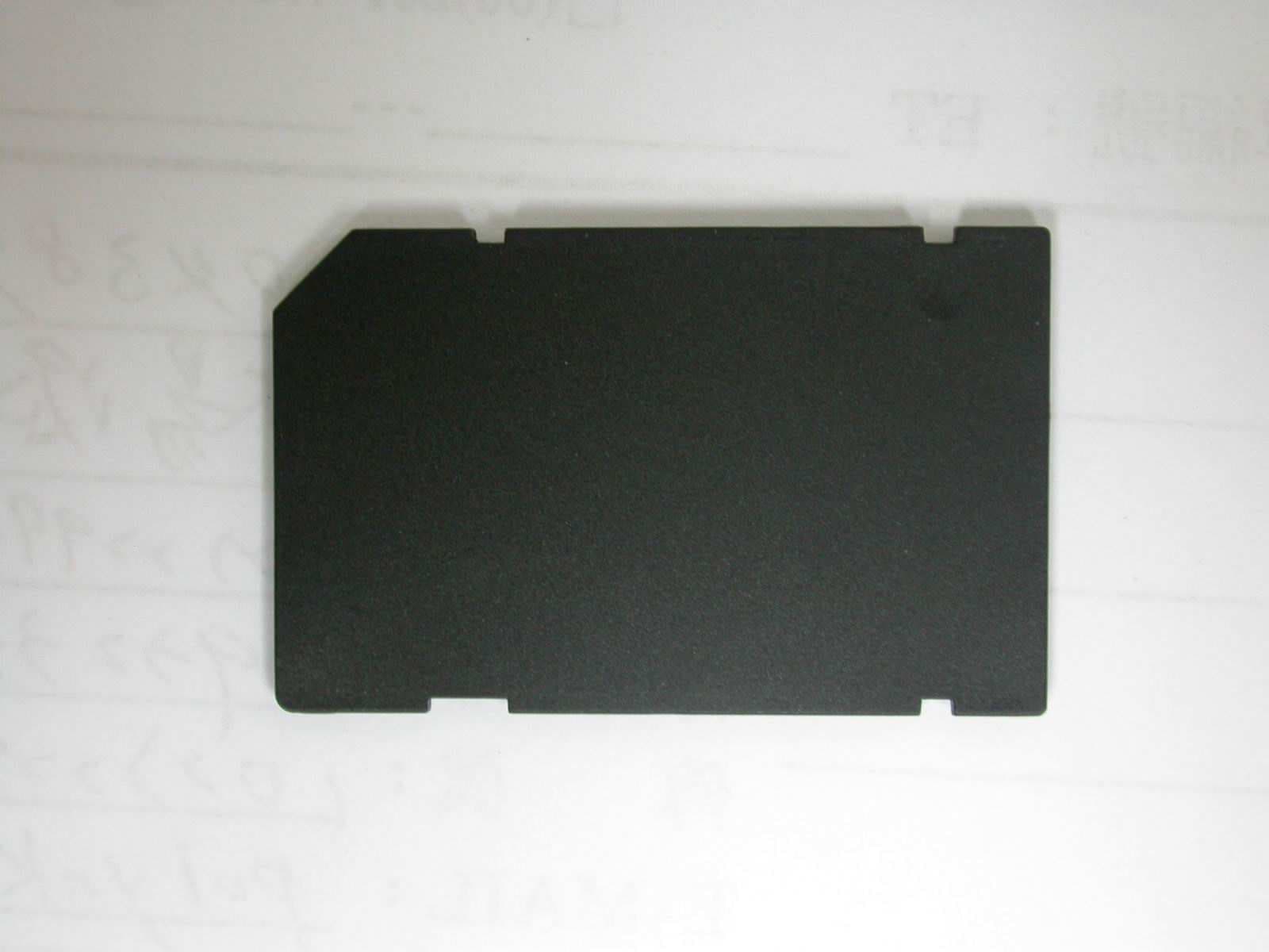
S2Y-WLAN-11B-G
Jan 29, 2006SDIO Wireless Lan Card
Equipment Class
DTS - Digital Transmission System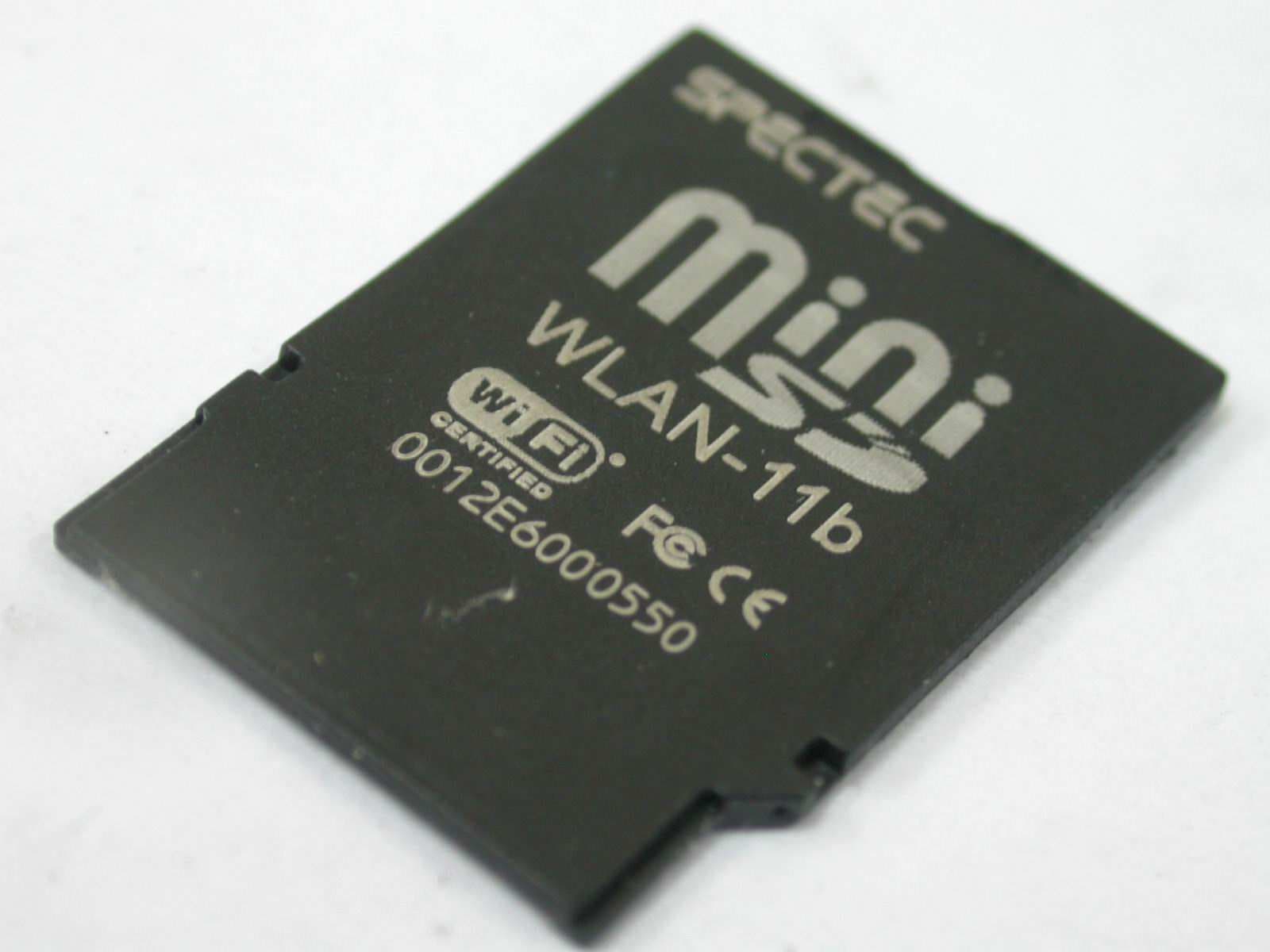
S2Y-MINIWLAN11B
Sep 07, 2005Mini SDIO Wireless LAN Card
Equipment Class
DTS - Digital Transmission System