S2Y-SDIOWLAN-11BSDIO Wireless Lan Card
Spectec Computer Co., Ltd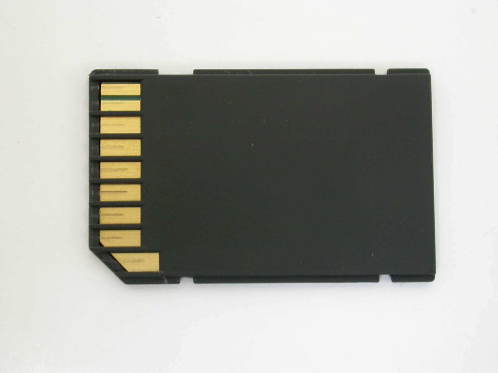
Click to zoom
Application Details
- Equipment Class
- DTS - Digital Transmission System
- Date of Grant
- May 05, 2005
- Application Purpose
- Original Equipment
- Date of Application
- May 05, 2005
- Equipment Note
- SDIO Wireless Lan Card
- Frequency Range
- 2412.00000000 - 2462.00000000
- Company
- Spectec Computer Co., Ltd
- Country
- Taiwan
Documents & Files
Document Text
Text extracted from the exhibit documents filed with the FCC. Open a document above to read the original.
Users Manual
Spectec SDIO WLAN Card User’s Manual (C) 2004. Spectec Computer Co., Ltd. 1 #SDW-820 - SDIO™ 802.11b 11Mbps WLAN Card The SDW-820 is the most smallest SD/IO IEEE802.11b WLAN card, point to point and point to multipoint with Windows-CE Pocket 2003 and Linux; will be also compatible with Windows XP in near further. SDW-820 Wi- Fi SD card wireless communications into a single card giving SDIO-enabled PDA the freedom to quickly transmit and receive data, images and music from thousands of 802.11b hotspots worldwide. The Ultra low power for longer battery hours Advanced Features: 802.11b Wi-Fi communications up to 11 Mbps High Speed Data Transfer Rate Support STA(ad hoc and infrastructure) and AP mode DCF/PCF support High Performance engine for WEP, TKIP and AES support On-Chip ADCs and DACs, RSSI, AGC Interface SDIO™ Ver1.0 (Support Ver1.1 Later) IEEE 802.11b / Wi-Fi Compliance. Three-wire interface for transceiver control Infrastructure mode, Ad-Hock. Frequency Fully integrated, 2.4GHz band direct conversion transceiver Channel Channel: Maximum 11 channels (US) and 14 channels (JPN) Connection: Infrastructure mode, Ad-hock mode TX Data Rate 1, 2, 5.5 11 Mbps Data Rate Transmission DS-SS System (Direct Sequence Speed Spectrum). Power Usage: Operating Voltage: PA: 3.0 to 3.6V, TRX: 2.7V Avg Operation: 185mA (While viewing Web). Receive Mode: 60mA Transmit Mode: 116ma for 15dbM Pout Sleep mode: 5uA Antenna Antenna Type: Inverted-F Antenna Antenna Gain: 3.4 dBi Approvals FCC, CE, Telec, DGT, IEEE 802.11b / Wi-Fi compliance Spectec SDIO WLAN Card User’s Manual (C) 2004. Spectec Computer Co., Ltd. 2 § SDW-820 software installation .Main menu window pop up when you insert the SDW-820 Installation CD by autorun: 1. Install the SDW-820 Driver & Utility version 2.14 ·Click Install to start your installation ·Preparing setup Spectec SDIO WLAN Card User’s Manual (C) 2004. Spectec Computer Co., Ltd. 3 ·Click Next. ·Click Install to start install the program. Spectec SDIO WLAN Card User’s Manual (C) 2004. Spectec Computer Co., Ltd. 4 ·Installing... ·Check if your mobile device connected with Host PC Spectec SDIO WLAN Card User’s Manual (C) 2004. Spectec Computer Co., Ltd. 5 ·Click Finish complete the driver installation. 2. Browse CD Contents: ·Including installation files and User’s Manual. Spectec SDIO WLAN Card User’s Manual (C) 2004. Spectec Computer Co., Ltd. 6 3. Contact Us: ·For further information & S/W upgrade , please visit SPECTEC website: http://www.spectec.com.tw or E-mail to : [email protected] 4. Exit: ·Thank you for using Spectec SDIO WLAN Card Spectec SDIO WLAN Card User’s Manual (C) 2004. Spectec Computer Co., Ltd. 7 FCC Information: Note: The equipment has been tested and found to comply with the limits for a Class B Digital Device, pursuant to part 15 of the FCC Rules. These limits are designed to provide reasonable protection against harmful interference in a residential installation. This equipment generates, uses and can radiate radio frequency energy and, if not installed and used in accordance with the instruction, may cause harmful interference to radio communication. However, there is no grantee that interference will not occur in a particular installation. If this equipment dose cause harmful interference to radio or television reception, which can be determined by turning the equipment off and on , the user is encouraged to try to correct the interference by one or more of the following measures: --Reorient or relocate the receiving antenna. --Increase the separation between the equipment and receiver. --Connect the equipment into an outlet on a circuit different from that to which the receiver is connected. --Consult the dealer or an experienced radio/TV technician for help. This device complies with Part 15 of the FCC Rules. Operation is subject to the following two conditions: (1) this device may not cause harmful interference, and (2) this device must accept any interference received, including interference that may cause undesired operation. The changes or modifications not expressly approved by the party responsible for compliance could void the user’s authority to operate the equipment. To comply with the FCC RF exposure compliance requirements, this device and its antenna must not be co-located or operating to conjunction with any other antenna or transmitter.
Cover Letter(s)
Helen Zhao Subject: FW: Spectec Computer Co., Ltd., FCC ID: S2Y-SDIOWLAN-11B, Assessment NO.: AN05T4701, Notice#2 5/6/2005 From: hsieh Sent: Wednesday, May 04, 2005 6:08 AM To: Helen Zhao Subject: Re: Spectec Computer Co., Ltd., FCC ID: S2Y-SDIOWLAN-11B, Assessment NO.: AN05T4701, Notice#2 Dear Helen, Attached please find the Schematics, Internal Photos, Setup Photos and New Test Report. Re-Q#1: Attached. Re-Q#2: Attached. Re-Q#3: Peak power meter. Re-Q#4: Please see the new test report and setup photos. Any questions please feel free to contact with me. Thank you for your review and propose. regards, Joe From: Compliance Certification Services [mailto:[email protected]] Sent: Wed 4/13/2005 9:13 PM Subject: Spectec Computer Co., Ltd., FCC ID: S2Y-SDIOWLAN-11B, Assessment NO.: AN05T4701, Notice#2 Question #1: Please resubmit Schematics exhibit. It is not readable. Question #2: Please resubmit internal photos. They are too small. Question #3: Please specify clearly which test equipment you were using to measure max. peak power: spectrum analyzer or peak power meter. Question #4: The SD card is an end product for portable application. It's not appropriate or sufficient to demonstrate compliance by testing the EUT with an extension card outside the host device only. Please retest radiated emission including restricted bandedge when EUT is inserted into the host device. Best regards, Helen Zhao The items indicated above must be submitted before processing can continue on the above referenced application. Failure to provide the requested information within 30 days of the original e-mail date may result in application dismissal and forfeiture of the filing fee. Also, please note that partial responses increase processing time and should not be submitted. Any questions about the content of this correspondence should be directed to the e-mail address listed below the name of the sender.
External Photos
ETC Report No.: ET94S-02-100-01 Page A1 of A1 FCC ID: S2Y-SDIOWLAN-11B ANNEX A: EXTERNAL CONSTRUCTION PHOTOS OF EUT 1. Outside view 1 of EUT 2. Outside view 2 of EUT
ID Label/Location Info
FCC ID Label / Location FCC ID:S2Y-SDIOWLAN-11B
Test Report
ETC Report No. : ET94S-02-100-01 Sheet 1 of 48 Sheets FCC ID. :S2Y-SDIOWLAN-11B Rev. No 1.0 CONFORMANCE TEST REPORT FOR FCC 47 CFR, Part 15 Subpart C Report No.: ET94S-02-100-01 Client: Spectec Computer Co.,Ltd Product: SDIO Wireless Lan Card Model: WLAN-11b FCC ID: S2Y-SDIOWLAN-11B Manufacturer/supplier: Spectec Computer Co.,Ltd. Date test item received: 2005/02/17 Date test campaign completed: 2005/05/04 Date of issue: 2005/05/05 The test result only corresponds to the tested sample. It is not permitted to copy this report, in part or in full, without the permission of the test laboratory. Total number of pages of this test report: 48 pages Total number of pages of photos: External photos 1 pages Internal photos 1 pages Setup photos 3 pages Test Engineer Checked By Approved By Mark Mark Joe Hsieh ELECTRONICS TESTING CENTER, TAIWAN NO.8, LANE 29, WEN-MING RD., LO-SHAN TSUN, KUI-SHAN HSIANG, TAOYUAN HSIEN 333 TAIWAN, R.O.C. TEL: (03) 3276170~4 INT: +886-3-3276170~4 FAX: (03) 3276188 INT: +886-3-3276188 ETC Report No. : ET94S-02-100-01 Sheet 2 of 48 Sheets FCC ID. :S2Y-SDIOWLAN-11B Rev. No 1.0 Client : Spectec Computer Co.,Ltd Address : 6F NO.92 NANKING E. RD. SEC.5 , TAIPEI , TAIWAN , R.O.C Manufacturer : Spectec Computer Co.,Ltd Address : 6F No.92 Nanking E. Rd. Sec.5 , Taipei , Taiwan , R.O.C EUT : SDIO Wireless Lan Card Trade name : Spectec Model No. : WLAN-11b Power Source : 3.3V DC Regulations applied : FCC 47 CFR, Part 15 Subpart C (2004) The testing described in this report has been carried out to the best of our knowledge and ability, and our responsibility is limited to the exercise of reasonable care. This certification is not intended to believe the sellers from their legal and/or contractual obligations. The compliance test is only certified for the test equipment and the results of the testing report relate only to the item tested. The compliance test of this report was conducted in accordance with the appropriate standards. It’s not intention to assure the quality and performance of the product. This report shall not be reproduced except in full, without the approval of ETC. This report must not be used by the client to claim product endorsement by NVLAP or any agency of the U.S. Government. Laboratory Introduction: Electronics Testing Center, Taiwan is recognized, filed and mutual recognition arrangement as following: 1 ISO9001: TüV Product Service 2 ISO/IEC 17025: BSMI, CNLA, DGT, NVLAP, CCIBLAC, UL, Compliance 3 Filing: FCC, Industry Canada, VCCI 4 MRA: Australia, Hong Kong, New Zealand, Singapore, USA, Japan, Korea, China, APLAC through CNLA 5 FCC Registration Number: 90588, 91094, 91095 NVLAP Lab Code 200133-0 ETC Report No. : ET94S-02-100-01 Sheet 3 of 48 Sheets FCC ID. :S2Y-SDIOWLAN-11B Rev. No 1.0 Table of Contents Page 1 GENERAL INFORMATION ................................................................................................................ 5 1.1 Product Description................................................................................................................................5 1.2 Characteristics of Device.......................................................................................................................5 1.3 Test Methodology..................................................................................................................................5 1.4 Test Facility............................................................................................................................................5 2 PROVISIONS APPLICABLE............................................................................................................... 6 2.1 Definition...............................................................................................................................................6 2.2 Requirement for Compliance.................................................................................................................7 2.3 Restricted Bands of Operation...............................................................................................................9 2.4 Labeling Requirement............................................................................................................................9 2.5 User Information..................................................................................................................................10 3. SYSTEM TEST CONFIGURATION ................................................................................................. 11 3.1 Devices for Tested System...................................................................................................................11 4 CONDUCTED EMISSION MEASUREMENT................................................................................. 12 4.1 Standard Applicable.............................................................................................................................12 4.2 Measurement Procedure.......................................................................................................................12 4.3 Conducted Emission Data....................................................................................................................13 4.4 Result Data Calculation........................................................................................................................20 4.5 Conducted Measurement Equipment...................................................................................................20 5 ANTENNA REQUIREMENT ............................................................................................................. 21 5.1 Standard Applicable.............................................................................................................................21 5.2 Antenna Construction and Directional Gain........................................................................................21 6 EMISSION BANDWIDTH…
Text truncated - open the document above for the full version.
Test Report
ETC Report No. : ET94S-02-100-01 Sheet 27 of 48 Sheets FCC ID. :S2Y-SDIOWLAN-11B Rev. No 1.0 7 OUTPUT POWER MEASUREMENT 7.1 Standard Applicable For direct sequence system, according to 15.247(b), the maximum peak output power of the transmitter shall not exceed 1 Watt. If transmitting antennas of directional gain greater than 6 dBi are used, the power shall be reduced by the amount in dB that the directional gain of the antenna exceeds 6 dBi. 7.2 Measurement Procedure 1. Check the calibration of the measuring instrument using either an internal calibrator or a known signal from an external generator. 2. Position the EUT as shown in figure 2. Turn on the EUT and connect its antenna terminal to measurement instrument via a low loss cable. Then set it to any one measured frequency within its operating range. 3. Measure the highest amplitude appearing on spectral display and record the level to calculate result data. 4. Repeat above procedures until all frequencies measured were complete. 7.3 Measurement Equipment Equipment Manufacturer Model No. Next Cal. Due Power Meter Boonton 4532 06/13/2005 Peak Power Sensor Boonton 56518 07/21/2005 ETC Report No. : ET94S-02-100-01 Sheet 28 of 48 Sheets FCC ID. :S2Y-SDIOWLAN-11B Rev. No 1.0 7.4 Measurement Data Test Date: Apr. 29, 2005 Temperature: 15 °C Humidity: 71 % Channel Frequency (MHz) Data Transfer Rate (Mbps) Reading (dBm) Attenuator & Cable Loss (dB) Maximum Peak Output Power (dBm) Maximum Peak Output Power (mW) FCC Limit (mW) 1 12.264 0.5 12.764 18.897 1000 2 12.316 0.5 12.816 19.125 1000 5.5 12.333 0.5 12.833 19.200 1000 1 2412 11 12.712 0.5 13.212 20.950 1000 1 11.562 0.5 12.062 16.077 1000 2 11.475 0.5 11.975 15.758 1000 5.5 11.424 0.5 11.924 15.574 1000 6 2437 11 11.510 0.5 12.010 15.886 1000 1 11.355 0.5 11.855 15.329 1000 2 11.268 0.5 11.768 15.024 1000 5.5 11.251 0.5 11.751 14.966 1000 11 2462 11 11.406 0.5 11.906 15.510 1000 Note: The estimated measurement uncertainty of the result measurement is ±1.5dB(1GHz ≦ f ≦ 18GHz) ETC Report No. : ET94S-02-100-01 Sheet 29 of 48 Sheets FCC ID. :S2Y-SDIOWLAN-11B Rev. No 1.0 8 POWER DENSITY MEASUREMENT 8.1 Standard Applicable According to 15.247(d), for direct sequence systems, the transmitted power density averaged over any 1 second interval shall not be greater than 8 dBm in any 3 kHz bandwidth within these bands. 8.2 Measurement Procedure 1. Check the calibration of the measuring instrument using either an internal calibrator or a known signal from an external generator. 2. Position the EUT as shown in figure 2. Turn on the EUT and connect its antenna terminal to measurement instrument via a low loss cable. Then set EUT to any one measured frequency within its operating range and make sure the instrument is operated in its linear range. 3. Adjust the center frequency of spectrum analyzer on highest level appearing on spectral display within a 300 kHz frequency span. 4. Set the spectrum analyzer on a 3 kHz resolution bandwidth and 10 kHz video bandwidth as well as max. hold function, then record the measurement result. 5. Repeat above procedures until all measured frequencies were complete. 8.3 Measurement Equipment Equipment Manufacturer Model No. Next Cal. Due Spectrum Analyzer Hewlett-Packard 8564EC 09/16/2005 ETC Report No. : ET94S-02-100-01 Sheet 30 of 48 Sheets FCC ID. :S2Y-SDIOWLAN-11B Rev. No 1.0 8.4 Measurement Data Test Date: Apr. 29, 2005 Temperature: 15 °C Humidity: 71 % Channel Frequency (MHz) Data Transfer Rate (Mbps) Reading (dBm) Cable Loss (dB) Peak Power Spectral Density (dBm) FCC Limit (dBm) Chart 1 -20.00 0.5 -19.50 8 - 2 -19.00 0.5 -18.50 8 - 5.5 -13.33 0.5 -12.83 8 - 1 2412 11 -12.33 0.5 -11.83 8 Page 31 1 -20.50 0.5 -20.00 8 - 2 -19.50 0.5 -19.00 8 - 5.5 -14.16 0.5 -13.66 8 - 6 2437 11 -13.00 0.5 -12.50 8 Page 32 1 -21.66 0.5 -21.16 8 - 2 -20.33 0.5 -19.83 8 - 5.5 -15.16 0.5 -14.66 8 - 11 2462 11 -14.16 0.5 -13.66 8 Page 33 Note: 1. Please refer to page 31 to page 33 for chart 2. The estimated measurement uncertainty of the result measurement is ±1.5dB(1GHz ≦ f ≦ 18GHz) ETC Report No. : ET94S-02-100-01 Sheet 31 of 48 Sheets FCC ID. :S2Y-SDIOWLAN-11B Rev. No 1.0 ETC Report No. : ET94S-02-100-01 Sheet 32 of 48 Sheets FCC ID. :S2Y-SDIOWLAN-11B Rev. No 1.0 ETC Report No. : ET94S-02-100-01 Sheet 33 of 48 Sheets FCC ID. :S2Y-SDIOWLAN-11B Rev. No 1.0 ETC Report No. : ET94S-02-100-01 Sheet 34 of 48 Sheets FCC ID. :S2Y-SDIOWLAN-11B Rev. No 1.0 9 SPURIOUS EMISSION - RF CONDUCTED MEASUREMENT 9.1 Standard Applicable According to 12.247 (c) , in any 100 kHz bandwidth outside the frequency band in which the spread spectrum or digitally modulated intentional radiator is operating, the radio frequency power that is produced by the intentional radiator shall be at least 20 dB below that in the 100 kHz bandwidth within the band that contains the highest level of the desired power, based on either an RF conducted or a radiated measurement. Attenuation below the general limits specified in Section 15.209(a) is not required. In addition, radiated emissions which fall in the restricted bands, as defined in Section 15.205(a), must also comply with the radiated emission limits specified in Section 15.209(a) (see Section 15.205(c)). 9.2 Measurement Procedure 1. Check the calibration of the measuring instrument using either an internal calibrator or a known signal from an external generator. 2. Position the EUT as shown in figure 2. Turn on the EUT and connect its antenna terminal to measurement instrument via a low loss cable. Then set it to any one measured frequency within its operating range and make sure the instrument is operated in its linear range. 3. Set both RBW and VBW of spectrum analyzer to 100 kHz with a convenient frequency span including 100kHz bandwidth from band edge. 4. Measure the highest amplitude appearing on spectral display and set it as a reference level. Plot the graph with marking the highest point and edge frequency. 5. Repeat above procedures until all measured frequenc…
Text truncated - open the document above for the full version.
Test Setup Photos
ETC Report No.:ET94S-02-100-01Sheet 1 of 2 Sheets FCC ID: S2Y-SDIOWLAN-11B 1. Radiated Measurement Photos X axis ETC Report No.:ET94S-02-100-01Sheet 2 of 2 Sheets FCC ID: S2Y-SDIOWLAN-11B Y axis Z axis
Contact Information
Applicant
S.T. Joung(General manager)
Test Firm
Electronics Testing Center, TaiwanWin-Po Tsai
Technical Specifications
| # | Rule Parts | Frequency Range | Power Output |
|---|---|---|---|
| 1 | 15C | 2.41 GHz - 2.46 GHz | 20.95 mW |
Other Applications from Spectec Computer Co., Ltd
S2Y-SDWLAN11BGN
Dec 26, 2012SDW-829
Equipment Class
DTS - Digital Transmission System
S2Y-SDJ731ZD
Mar 18, 2012SDJ-731
Equipment Class
DTS - Digital Transmission System
S2Y-MINISDW11BG
Jul 01, 2007Mini SDIO Wireless 11b/g
Equipment Class
DTS - Digital Transmission System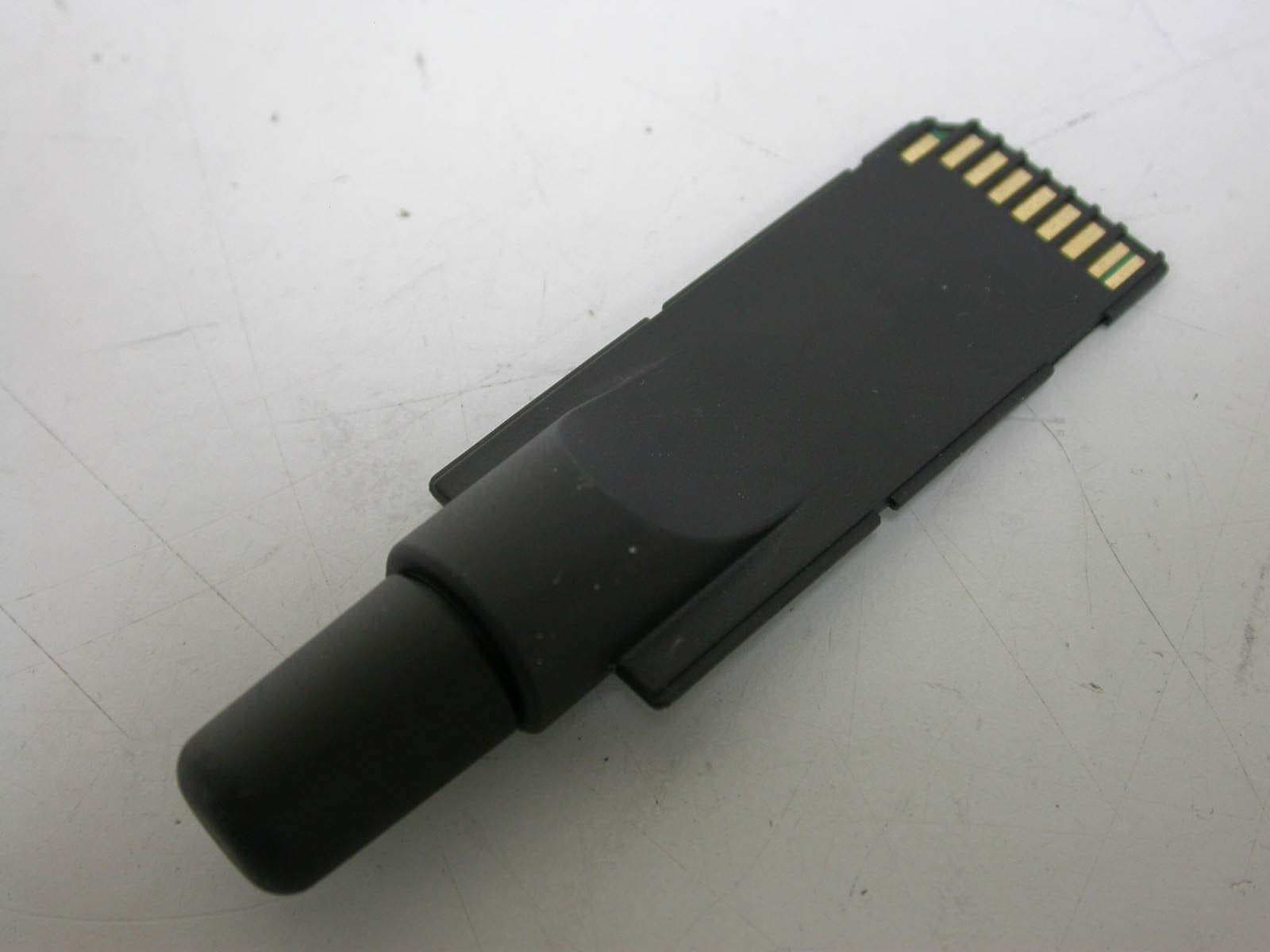
S2Y-SDG812BTGPS
Jun 17, 2007SD BT GPS
Equipment Class
DSS - Part 15 Spread Spectrum Transmitter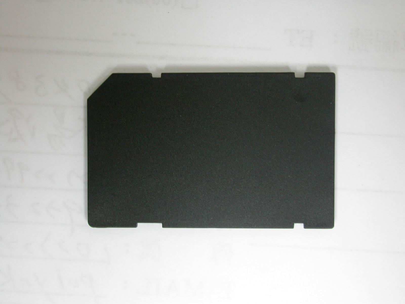
S2Y-WLAN-11B-G
Jan 29, 2006SDIO Wireless Lan Card
Equipment Class
DTS - Digital Transmission System