S9PBSC1001BSC1001 Base Unit
LifeShield, Inc.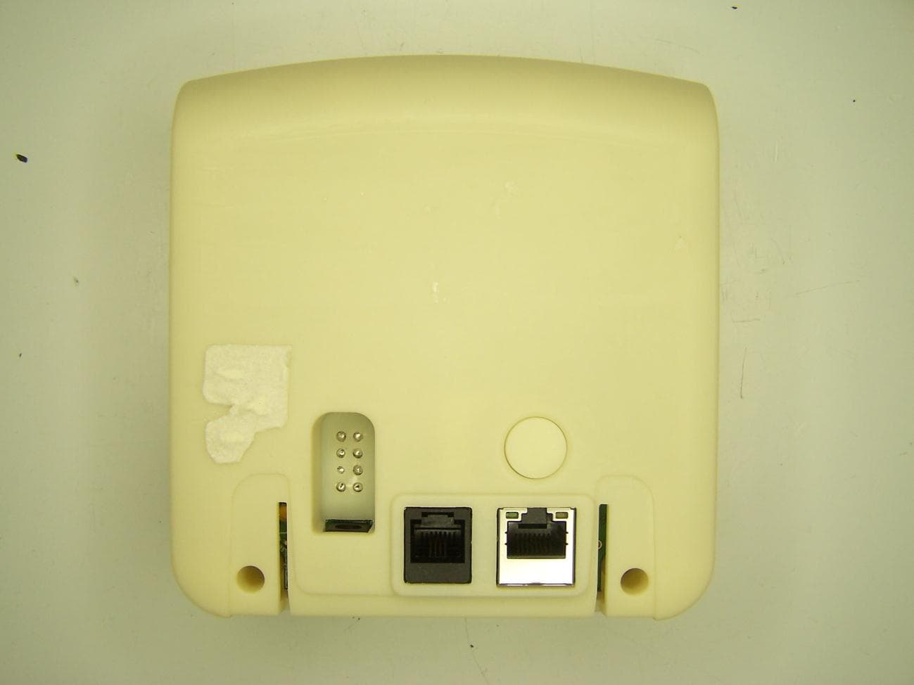
Click to zoom
Application Details
- Equipment Class
- DSS - Part 15 Spread Spectrum Transmitter
- Date of Grant
- Mar 21, 2011
- Application Purpose
- Original Equipment
- Date of Application
- Mar 21, 2011
- Equipment Note
- BSC1001 Base Unit
- Frequency Range
- 2401.00000000 - 2483.00000000
- Company
- LifeShield, Inc.
- Country
- United States
Documents & Files
Document Text
Text extracted from the exhibit documents filed with the FCC. Open a document above to read the original.
Users Manual
Base Installation Instructions Model BSC1001 CAUTION: This equipment cannot report an alarm over the telephone line when other non-LifeShield equipment (telephone, answering system, computer modem, etc.) conected to the same line is in use. Battery Warning Rechargeable Lithium Ion Batteries Must Be Recycled or Disposed of Properly. Do not mutilate the battery pack. Do not dispose of the battery pack in a fire due to risk of explosion. LIFESHIELD LIMITED WARRANTY FOR PRODUCTS AND ACCESSORIES PURCHASED IN THE UNITED STATES OR CANADA WHAT IS COVERED UNDER THIS WARRANTY Subject to the limitations and exclusions contained below, LifeShield, Inc. (“LifeShield”) warrants the LifeShield-branded (including all embedded software) sold by LifeShield for use with the LifeShield Security System (the “Products”) to be free from defects in materials and workmanship under normal consumer usage and in accordance with the accompanying instructions and documentation, for the period(s) set forth below. This warranty extends only to the first consumer purchaser, and is not transferable. LifeShield, at its option, will at no charge repair, replace or refund the purchase price of any Products that do not conform to this limited warranty. We may use functionally equivalent reconditioned/ refurbished/pre-owned or new Products or parts and we may retain all replaced Products or parts. No data added to your Products, including but not limited to component names and system preferences, will be reinstalled. This limited warranty is the consumer’s exclusive remedy, and applies to new Products purchased by consumers in the United States or Canada, which are accompanied by this written warranty. PRODUCTS COVERED/LENGTH OF COVERAGE (the “Warranty Period”) New Products: One (1) year from the date of purchase by the first consumer purchaser of the Product. Products That Are Repaired or Replaced. The balance of the original warranty or for ninety (90) days from the date returned to the consumer, whichever expires later. Batteries. Only batteries whose fully charged capacity falls below 80% of their rated capacity and batteries that leak are covered by this limited warranty. HOW TO OBTAIN WARRANTY SERVICE OR OTHER INFORMATION To obtain service or information, please call: LifeShield Customer Service at: 1-888-392-2044 Or email us at: [email protected] You will receive instructions on how to ship the Products, at your expense, to a LifeShield Authorized Repair Center. To obtain service, you must include: a) a copy of your receipt, bill of sale or other comparable proof of purchase b) a written description of the problem c) the complete physical address of the location where the system was installed and most importantly d) your address and telephone number and, e) the “Return Merchandise Authorization” or “RMA” number that LifeShield provides to you WHAT IS NOT COVERED (EXCLUSIONS) Normal Wear and Tear. Periodic repair and replacement of parts due to normal wear and tear are excluded from coverage. Ornamental Decorations. Ornamental decorations, such as emblems and graphics and other decorative elements, are excluded from coverage. Abuse & Misuse. Defects or damage that result from the following are excluded from coverage: a) improper operation, storage, misuse or abuse, accident or neglect, such as physical damage (cracks, scratches, etc.) to the surface of the Product; b) contact with moisture, liquids, water, rain, extreme humidity, heavy perspiration or makeup, sand, dirt or the like, food, or proximity to or exposure to heat or cold, fire, flood, or lightning; c) other acts which are inconsistent with the instructions and documentation that accompany the Products; and d) use of the Products with any system other than the LifeShield Security System. Use of Non-LifeShield Products and Accessories. Defects or damage that result from the use of Non-LifeShield branded or certified products, accessories, software or other peripheral equipment are excluded from coverage, including without limitation defects or damage to Products that result from such use are excluded from coverage. Unauthorized Service or Modification. Defects or damages resulting from service, testing, adjustment, installation, maintenance, alteration, including without limitation, software changes, or modification in any way by someone other than LifeShield, or its authorized agents, are excluded from coverage. Altered Products. Products with the following characteristics are excluded from coverage: a) serial numbers or date tags that have been removed, altered or obliterated; b) broken seals or Products that show evidence of tampering; c) mismatched board serial numbers; or d) nonconforming or non-LifeShield housings, antennas, or parts. Communication Services. Defects, damages, or the failure of Products due to any communication service or signal not provided directly by LifeShield is excluded from coverage. Out of Warranty Products. Defects or damages reported to LifeShield after the Warranty Period are excluded from coverage. Other Exclusions and Limitations ANY IMPLIED WARRANTIES, INCLUDING WITHOUT LIMITATION THE IMPLIED WARRANTIES OF MERCHANTABILITY AND FITNESS FOR A PARTICULAR PURPOSE, ARE HEREBY LIMITED IN DURATION TO THE TERM OF THIS EXPRESSED WARRANTY. THE REPAIR OR REPLACEMENT AS PROVIDED UNDER THIS EXPRESS LIMITED WARRANTY IS THE SOLE AND EXCLUSIVE REMEDY OF THE CONSUMER, AND LIFESHIELD’S SOLE AND EXCLUSIVE LIABILITY HEREUNDER, AND IS PROVIDED IN LIEU OF ALL OTHER WARRANTIES, EXPRESS OR IMPLIED. IN NO EVENT SHALL LIFESHIELD BE LIABLE, WHETHER IN CONTRACT, TORT (INCLUDING NEGLIGENCE) OR OTHERWISE, FOR DAMAGES IN EXCESS OF THE PURCHASE PRICE OF THE PRODUCT GIVING RISE TO THE DAMAGES, OR FOR ANY INDIRECT, INCIDENTAL, SPECIAL, PUNITIVE, EXEMPLARY OR CONSEQUENTIAL DAMAGES OF ANY KIND, OR LOSS OF REVENUE OR PROFITS, LOSS OF BUSINESS, LOSS OF INFORMATION OR DATA, SOFTWARE OR APPLICATIONS OR OTHER FINANCIAL LOSS ARISING OUT OF OR IN CONNECTION WITH T…
Text truncated - open the document above for the full version.
Users Manual
User Manual Important Safety Instructions IMPORTANT SAFETY INSTRUCTIONS [www.LifeShield.com] [ii] When using this system, basic safety precautions should always be followed to reduce the risk of fire, electric shock or personal injury. 1.Read and understand Quick Setup Guide and User Manual instructions. 2.Follow all warnings and instructions marked on the individual components provided in the system. 3.Unplug individual components from AC outlets before cleaning. Do not use liquid or aerosol cleaners. Use a damp cloth for cleaning. 4.Do not use individual components near water (such as sinks, bathtubs or swimming pools). 5.Place individual components securely on stable surface. 6.Do not cover slots and openings on any of the individual system components. They are provided for ventilation to reduce overheating, and as audio sirens to alert you of an alarm. 7.Use only power source marked on system components. If you are not sure of the type of power supplied to your home, consult your local power company. 8.Do not place objects on the power cord. Install the system components where no one can trip on the cords. 9.Do not overload wall outlets or extension cords. This can result in the risk of fire or electric shock. 10. Never push any objects through slots in system components. This may result in the risk of fire or electric shock. Never spill any liquid on any of the system components. 11. To reduce risk of electric shock, do not disassemble any components provided in the system. If you are having a problem, please call LifeShield Customer Support. 12. Unplug the system components from the wall outlet and call Customer Support when the following conditions occur: A. When power supply cord or plug is damaged or worn. B. If liquid has been spilled on a component. C. If a component has been exposed to rain or water. D. If a component has been dropped or physically damaged. E. If a component exibits a distinct change in performance. 13. During thunderstorms, avoid using telephone except cordless types. Use a surge protector to protect equipment. 14. Do not use these components to report a gas leak when in the vicinity of the leak. Battery Safety Instructions: To reduce the risk of fire or injury, read and follow these instructions. 1.Use only the battery(ies) specified. There is a risk of explosion if you replace the battery(ies) with the incorrect battery type. 2.Rechargeable batteries must be disposed of properly and may need to be recycled. Check with local waste mangement codes for special disposal instructions. 3.Do not burn, disassemble, mutilate or puncture the battery(ies). The battery(ies) contain toxic material that could be released, resulting in injury. 4. Exercise care in handling battery(ies) in order not to short the battery(ies) to conductive material. 5.Charge the battery(ies) provided with, or identified for use with, the system components only in accordance with the instructions and limitations specified in this manual. List of Contents LIST OF CONTENTS [www.LifeShield.com] [iii] LifeShield Home Security Introduction.................................................................................................................................................1 Overview .............................................................................................................................................................................................1 Features ...............................................................................................................................................................................................2 Displays and Menus ...........................................................................................................................................................................3 LifeShield.com .....................................................................................................................................................................................5 Alarm Monitoring................................................................................................................................................................................7 Installing Your Security System............................................................................................................................................................9 Installing the Base ..............................................................................................................................................................................9 Installing the Handset ......................................................................................................................................................................11 Installing the Console.......................................................................................................................................................................14 Installing the Grid Extender ............................................................................................................................................................19 Installing the Sensor .........................................................................................................................................................................21 Installing the Keychain Remote.......................................................................................................................................................25 Installing the Siren Detector ............................................................................................................................................................27 Installing the Motion Sensor............................................................................................................................................................32 Installing the Glassbreak Sensor......................................…
Text truncated - open the document above for the full version.
Users Manual
User Codes USING YOUR SECURITY SYSTEM [www.LifeShield.com] [60] 1.Go to www.LifeShield.com 2.Enter your User Nameand Password 3.Navigate to Settings tab, then to User Codes 4.Click Add (Figure 37) 5.Fill in the requested fields (Figure 38) 6.Click Continue 7.Click Submit Changeswhen requested Creating User Codes via www.LifeShield.com (Figures 37 and 38): Figure 38. LifeShield - Create/Edit User Code Screen Figure 37. LifeShield - User Code Screen 1.Go to www.LifeShield.com 2.Enter your User Nameand Password 3.Navigate to Settings tab, then to User Codes 4.Editon the same line as the user (Figure 37) 5.Adjacent to Keychain Remotefield, click Remove Keychain(Figure 38) 6.Click Continue 7.Click Submit Changeswhen requested To Delete a Keychain Remote from a User via www.LifeShield.com: USING YOUR SECURITY SYSTEM [www.LifeShield.com] [61] Suppressing Trouble Sounds t You can only suppress Trouble Sounds when the system is dis- armed. If you suppress Trouble Sounds after a first trouble condition, and then a second trouble condition occurs, Trouble Sounds will start again. This might happen, for ex- ample, if you lose AC power, and then lose Internet a few minutes later. The system provides Trouble Soundsto alert the user that it requires attention. Trouble Sounds can be generated as a result of a low battery, the loss of Internet or phone connection, etc. You can limit the hours during the day when Trouble Sounds are sounded and you can temporarily suppress the sounds until you can address the trouble condition. Suppressing Trouble Sounds (Handset/Console) To suppress a Trouble Sound while it is occurring, on a Handsetor Console : 1.Press CANCEL/OFF 2.Press OK You can control the length of time that Trouble Sounds are suppressed (when you press CANCEL/OFF), on a Handset or Console: 1.Press MENU 2.Scroll to Security Setup, press SELECT 3.Enter your Master Code 4.Scroll to Suppress Trouble, press SELECT 5.Scroll to the desired setting (The settings range from 0 to 48 hours. Factory default is 24 hours.) Setting the Time of Day when Trouble Sounds are Disabled (via www.LifeShield.com) You can control the hours of the day when Trouble Sounds are disabled/silenced, such as while you are sleeping. Some condi- tions, like No Internet or No AC are brief and corrected quickly by the utility and you may not want to be awakened. Note that there must be at least 1 hour per day when Trouble Sounds are not silenced. (Figure 39): 1.Go to www.LifeShield.com 2.Enter your User Nameand Password 3.Click Settings 4.Navigate to System Settings 5.Click Edit 6.Select desired Trouble Silence Start andEnd Time 7.Click Continue 8.Click Submitwhen requested Figure 39. LifeShield - Edit System Settings Screen USING YOUR SECURITY SYSTEM [www.LifeShield.com] [62] Event Log/Network Configuration Alarm Event Log (Handset/Console) For Alarm Monitoring subscribers the system will log all messages (in an Event Log) sent to the Alarm Monitoring Center. This is separate from the entire Recent Eventlog on www.LifeShield.com. These messages can be viewed from your Handset or Console : 1.Press MENU 2.Scroll to Security Setup, press SELECT 3.Enter your Master Code 4.Scroll to Event Log, press SELECT Network Configurations Your LifeShield system usually connects to your Internet (broadband) network automatically using the same DHCP protocol as your PC or laptop. However, some networks use Static IP Addresses. If you are not familiar with Static IP Address, it is likely that your network does not have this requirement. If you do require a Static IP Address, complete this setup process from either your Handsetor Console: 1.Press MENU 2.Scroll to Security Setup, press SELECT 3.Scroll to Network Mode, press SELECT 4.Scroll to Address Type, press SELECT 5.SELECT Static, press OK 6.SELECT View/Edit 7.Enter the following information and press OK as you complete each step: IP Address Gateway SubnetMsk PrimDNS Second DNS MAC Address Power Outage Yo u r LifeShield Home Securitysystem operates on AC power and battery backup. In the event that both AC and battery power is lost while the system is armed, your system will automatically return to the armed state when the power is restored. After a complete AC and battery outage, the system will wait 1 minute before responding to Sensoractivity once power is re- stored. i You can receive notifications on your email, mobile device, and/or Home Alert for any event in your system. Set these up at www.LifeShield.com, Security tab, Recent Events window, notification setup button. Home Connect USING YOUR SECURITY SYSTEM [www.LifeShield.com] [63] The Home Connectfeature gives you access to view and control another LifeShield Home Security system if the owner of that system gave you proper permission. Example uses include an elderly parent who has special needs or a neighbor that is going on vacation. This same feature allows you to invite someone to look in on your system. The LifeShield Home Connect feature offers 2 levels of access as shown in Table 3: Access LevelDescription Alarm Only Receive Alarm and System Notifications from the connected home’s system directly to your home as a Home Alert on LifeShield.com or via email. Full Control In addition to Alarm Only access, the connected home can be Armed and Disarmed from your system Handset, Console or LifeShield.com. Table 3: Home Connect Access Levels Inviting a Home Connect Participant To give a trusted friend or family member permission to access your system: 1.Go to www.LifeShield.com 2.Enter your User Nameand Password 3.Click on Home Connect tab 4.Click on Invite Someone Now(Figures 40 and 41) 5.Enter requested information(Figure 41) 6.Click Submit Once the participant has accepted your invitation, you will receive notice on the Invite Sent window. They will then be able to access your system.(Figure 42) Figure 41. LifeShield - Home Connect Invite Figure 40. LifeShield - Home Connect Tab Home Connect USING YOUR SECURITY SYSTEM [www.LifeShield.com]…
Text truncated - open the document above for the full version.
Users Manual
This guide will walk you through the set up of your LifeShield security system step by step. You will find all the components necessary for set up in either the Home Essential Kit or the Home Essential Kit–Cellular Ready. Base (Home Essential Kit only) Cellular Gateway (Home Essential Kit –Cellular Ready only) Console Sensors Keychain Remote © 2011 LifeShield Inc. All rights reserved. LifeShield is a registered trademark of LifeShield Inc. Quick Setup Guide Start Here CELLULAR GATEWAY SENSOR CONSOLE SENSOR SENSOR BASE IMPORTANT: FOLLOW STEPS IN EXACT ORDER. DO NOT SKIP AHEAD. Component Placement Suggestions: The LifeShield home security system you are about to set up is wireless. To maximize wireless coverage, plan to place the components throughout your home. Ideally, these components will be in different rooms on interior walls. A key consideration is making sure that all Sensors are within approximately 30 feet of one or more of the main components. NOW IS A GOOD TIME TO PLAN YOUR COMPONENT PLACEMENT Internet The Base connects the system to the Internet. Your Internet connection is likely located where your Modem/Router is placed. The Internet enables remote access to your system from LifeShield.com. The Internet is also the primary communication for reporting alarms to the alarm monitoring center. Cellular Gateway The Cellular Gateway automatically establishes a connection between your LifeShield system and the monitoring center. The best place to put this is on a high floor in your home since it’s dependant on your local cellular network. Communication Connections: 21 KEYChAIN REMOTESENSOR/MAGNET SYSTEM COMPONENTS Included with both hOME ESSENTIAL KIT AND hOME ESSENTIAL KIT –CELLULAR READY BASE hOME ESSENTIAL KIT ONLY CELLULAR GATEWAY hOME ESSENTIAL KIT– CELLULAR READY ONLY CONSOLE Locate Base near Modem/Router Remove the table stand, by sliding downward from the main body of the Base Insert the LifeShield LS220 Rechargeable Battery, observing correct polarity as shown Insert the power adapter plug fully into the jack on the back of the Base, then plug the power adapter into the wall outlet Connect the Ethernet cable between an available port on your router and the back of the Base 4 C B For installation of the Home Essential Kit, follow the instructions on this page. After completing Steps 1 & 2, go to page 5. IMPORTANT: FOLLOW STEPS IN EXACT ORDER. DO NOT SKIP AHEAD. Locate Console near frequently used door, ideally in different room than Base Connect battery (match red/black polarity) Connect power cord on back of Console Route power cord up through channel For table-top placement, snap stand into Console* Plug power cord into wall outlet A A B B C C D D E E F 3 FOLLOW ThE INSTRUCTIONS ON ThIS PAGE IF YOU PURChASED ThE hOME ESSENTIAL KIT 1 2 Connect Base Connects your LifeShield system to the Internet Connect Console Controls security and telephone functions CC B FF EE DD Console Back View Table Stand Table Stand B E D (Optional) Phone Cord Base Back View Power Adapter Ethernet Cable Modem/Router Table Stand Cellular Gateway Back View C For installation of the Home Essential Kit–Cellular Ready, follow the instructions on this page. After completing steps 1 & 2, go to page 5. Locate the Cellular Gateway, ideally on a high floor in your home Connect Battery (match red/black polarity) Plug Cellular Gateway into wall outlet Locate Console near frequently used door, ideally in different room than Cellular Gateway Connect battery (match red/black polarity) Connect power cord on back of Console Route power cord up through channel For table-top placement, snap stand into Console* Plug power cord into wall outlet A A B B C C D E F OPTIOnAL: COnnECTIng A PhOnE CORD FROM ThE BASE TO ThE TELEPhOnE wALL jACk PROvIDES A BACkuP PATh FOR ALARM COMMunICATIOnS IF YOuR InTERnET COnnECTIOn IS nOT FunCTIOnIng. IF PhOnE wALL jACk IS nOT AvAILABLE nEAR BASE LOCATIOn, YOu CAn COnnECT A PhOnE LInE TO ThE COnSOLE. *nOTE: FOR MOunTIng On wALL, SEE uSER MAnuAL.*nOTE: FOR MOunTIng On wALL, SEE uSER MAnuAL. FOLLOW ThE INSTRUCTIONS ON ThIS PAGE IF YOU PURChASED ThE hOME ESSENTIAL KIT–CELLULAR READY 1 2 Cellular Gateway Establishes a connection between your LifeShield system and monitoring center. Connect Console Controls security and telephone functions B Console Back View + - Battery CompartmentBattery Compartment Battery Power CordPower Cord Closed Door Open Door Sensors and Magnets create security for doors and windows. • When a door or window is closed, the Sensor and Magnet must be within 3/4" of each other • As a door or window is opened, the Sensor and Magnet separate causing the Sensor to chime or alarm Sensors IMPORTANT: DO NOT ASSEMBLE ANY OF ThE SENSOR PIECES UNTIL INSTRUCTED. Sensor Bracket Tape Bracket Magnet Magnet Tape Magnet Spacer (optional use) Bracket Spacer (optional use) SENSOR KIT CONTENTS 3/4" spacing Sensor Magnet Select door or window that you want to monitor with Bracket and Magnet in hand, select a location on the door or window for mounting* A B A *nOTE: whEn POSSIBLE, PLACE ThE BRACkET On ThE STATIOnARY FRAME OF DOOR OR wInDOw, AnD PLACE ThE MAgnET On ThE DOOR OR wInDOw ITSELF. Bracket Magnet Double-Hung Window Door Mounting window Mounting 3/4" spacing Figure 1. Level Orientation Figure 2. Angled Orientation Figure 3. Perpendicular Orientation Bracket Magnet D Figure 4. Perpendicular Orientation *nOTE: SPACERS In BOTTOM TRAY MAY BE uSED On ThE BRACkET OR MAgnET TO ADjuST ALIgnMEnT. C various orientations between the Bracket and Magnet may be used as long as 3/4" distance is not exceeded.* See Example in Figures 1-4 Once you have determined the appropriate location and orientation for the Bracket and Magnet, attach them with double-sided tape C D Mount Bracket & Magnet 3a B 56 3 For this step you will need your Console and Sensor: Remove battery tab using Console: Press MEnu Scroll to Security Setup, press SELECT (Scroll Button found on right side of Console) Enter default Master C…
Text truncated - open the document above for the full version.
Attestation Statements
LifeShield Security 770 Township Line Road Suite350 Yardley PA 19067 re: Model BSC1001 i. The hopping sequence is pseudorandom, all channels are used equally on average, the receiver input bandwidth is approximately equal to the transmit bandwidth and the receiver hops in sequence with the transmitted signal. ii. The system is designed to comply with all the regulations in 15.247 when the transmitter is presented with a continuous data. iii. The system does not coordinate its channel selection/hopping sequence with other frequency hopping systems for the express purpose of avoiding the simultaneous occupancy of individual hopping frequencies by multiple transmitters. Gregory C Berlin Director Hardware Engineering
ID Label/Location Info
LifeShield S9PBSC1001 Label Placement LifeShield S9PBSC1001 Label Te x t
ID Label/Location Info
MADE IN CHINA DISCONNECT PHONE CABLE BEFORE REMOVING BATTERY DOOR USE ONLY MODEL PSC0101 POWER ADAPTER MODEL:BSC1001 FCC ID: S9PBSC1001 Reg No US: S9PAL00BBSC1001 This device complies with Part 15 & 47 CFR part 68 FCC Rules. Operation is subject to the following two conditions: (1) this device may not cause harmful interference, and (2) this device must accept any interference received, including interference that may cause undesired operation. Privacy of communications may not be ensured when using this phone. 2.45" x 0.6" E113133 Electrical Safety
RF Exposure Info
§ 15.247(i) Maximum Permissible Exposure RF Exposure Requirements: §1.1307(b)(1) and §1.1307(b)(2): Systems operating under the provisions of this section shall be operated in a manner that ensures that the public is not exposed to radio frequency energy levels in excess of the Commission’s guidelines. RF Radiation Exposure Limit: §1.1310: As specified in this section, the Maximum Permissible Exposure (MPE) Limit shall be used to evaluate the environmental impact of human exposure to radiofrequency (RF) radiation as specified in Sec. 1.1307(b), except in the case of portable devices which shall be evaluated according to the provisions of Sec. 2.1093 of this chapter. MPE Limit Calculation: EUT’s operating frequencies between 2400 and 2483.5 MHz;. Highest radiated power (EIRP) = 20.2 mW. Therefore, Limit for Uncontrolled exposure: 1 mW/cm 2 . Equation from page 18 of OET 65, Edition 97-01 S = EIRP / 4R 2 where, S = Power Density mW/m 2 EIRP = Equivalent Isotropic Radiated Power R = Distance to the center of radiation of the antenna (20 cm for Mobile minimum distance) EIRP = 20.2 mW S = 20.2 / 4(3.1416)(20) 2 S = 0.004 mW/cm 2 Therefore, EUT meets the Uncontrolled Exposure limit at 20 cm.
Test Report
MET Laboratories, Inc. Safety Certification - EMI - Telecom Environmental Simulation 914 WEST PATAPSCO AVENUE ! BALTIMORE, MARYLAND 21230-3432 ! PHONE (410) 354-3300 ! FAX (410) 354-3313 33439 WESTERN AVENUE ● UNION CITY, CALIFORNIA 94587 ● PHONE (510) 489-6300 ● FAX (510) 489-6372 3162 BELICK STREET ● SANTA CLARA, CALIFORNIA 95054 ● PHONE (408 748-3585 ● FAX (510) 489-6372 The Nation’s First Licensed Nationally Recognized Testing Laboratory February 22, 2011 LifeShield, Inc. 1255 Drummers Lane, Suite 100 Wayne, PA 19087 Dear Louis Stilp, Enclosed is the EMC Wireless test report for compliance testing of the LifeShield, Inc., Base, Model # BSC1001 as tested to the requirements of Title 47 of the CFR, Ch. 1 (10-1-06 ed.), Part 15, Subpart B for a Class B Digital Device and FCC Part 15 Subpart C for Intentional Radiators. Thank you for using the services of MET Laboratories, Inc. If you have any questions regarding these results or if MET can be of further service to you, please feel free to contact me. Sincerely yours, MET LABORATORIES, INC. Jennifer Warnell Documentation Department Reference: (\LifeShield, Inc.\EMC30582-FCC247) Certificates and reports shall not be reproduced except in full, without the written permission of MET Laboratories, Inc. Electromagnetic Compatibility LifeShield, Inc. Cover Page Base, Model # BSC1001 CFR Title 47, Part 15B, 15.247 MET Report: EMC30582-FCC247 © 2011, MET Laboratories, Inc. Page ii of viii DOC-EMC702 6/18/2009 Electromagnetic Compatibility Criteria Test Report for the LifeShield, Inc. Base, Model # BSC1001 Tested under the FCC Certification Rules contained in Title 47 of the CFR, Parts 15 Subpart B for Class B Digital Devices & 15.247 Subpart C for Intentional Radiators MET Report: EMC30582-FCC247 February 22, 2011 Prepared For: LifeShield, Inc. 1255 Drummers Lane, Suite 100 Wayne, PA 19087 Prepared By: MET Laboratories, Inc. 914 W. Patapsco Ave Baltimore, MD 21230 Electromagnetic Compatibility LifeShield, Inc. Cover Page Base, Model # BSC1001 CFR Title 47, Part 15B, 15.247 MET Report: EMC30582-FCC247 © 2011, MET Laboratories, Inc. Page iii of viii DOC-EMC702 6/18/2009 Electromagnetic Compatibility Criteria Test Report for the LifeShield, Inc. Base, Model # BSC1001 Tested under the FCC Certification Rules contained in Title 47 of the CFR, Parts 15 Subpart B for Class B Digital Devices & 15.247 Subpart C for Intentional Radiators Dusmantha Tennakoon, Project Engineer Jennifer Warnell Electromagnetic Compatibility Lab Documentation Department Engineering Statement: The measurements shown in this report were made in accordance with the procedures indicated, and the emissions from this equipment were found to be within the limits applicable. I assume full responsibility for the accuracy and completeness of these measurements, and for the qualifications of all persons taking them. It is further stated that upon the basis of the measurements made, the equipment tested is capable of operation in accordance with the requirements of the FCC Rules Parts 15B, 15.247 under normal use and maintenance. Shawn McMillen, Wireless Manager, Electromagnetic Compatibility Lab Electromagnetic Compatibility LifeShield, Inc. Report Status Base, Model # BSC1001 CFR Title 47, Part 15B, 15.247 MET Report: EMC30582-FCC247 © 2011, MET Laboratories, Inc. Page iv of viii DOC-EMC702 6/18/2009 Report Status Sheet Revision Report Date Reason for Revision February 22, 2011 In…
Text truncated - open the document above for the full version.
Contact Information
Applicant
Louis Stilp(President)
Technical Contact
LifeShieldGregory C Berlin
[email protected]267-907-9789
1255 Drummers Lane · Wayne, Pennsylvania · United States
Test Firm
EUROFINS ELECTRICAL AND ELECTRONIC TESTING NA, INCGreg Kovolenko
Technical Specifications
| # | Rule Parts | Frequency Range | Power Output |
|---|---|---|---|
| 1 | 15C | 2.40 GHz - 2.48 GHz | 20.20 mW |
Other Applications from LifeShield, Inc.
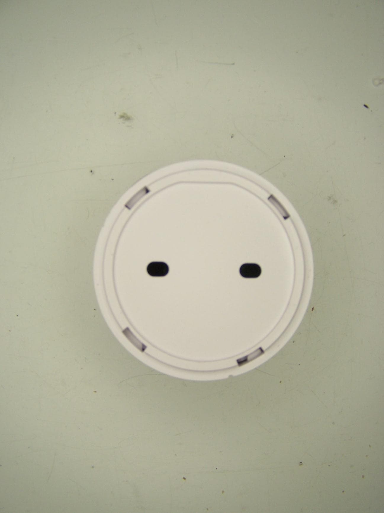
S9PSDC1001
Nov 14, 2012wireless sensor
Equipment Class
DSC - Part 15 Security/Remote Control Transmitter
S9PSNC1010
Feb 09, 2011Wireless Security Sensor
Equipment Class
DSC - Part 15 Security/Remote Control Transmitter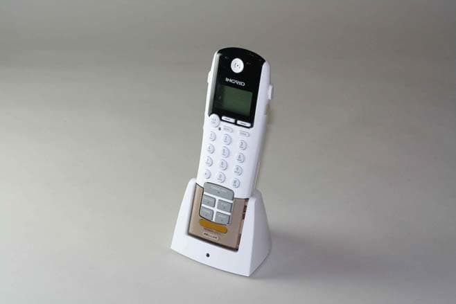
S9PHSC1000
Aug 07, 2007Wireless Grid Controller
Equipment Class
DSS - Part 15 Spread Spectrum Transmitter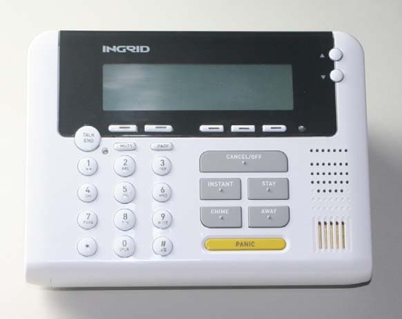
S9PKPC1000
Jun 19, 2007Wireless Security System Keypad
Equipment Class
DSS - Part 15 Spread Spectrum Transmitter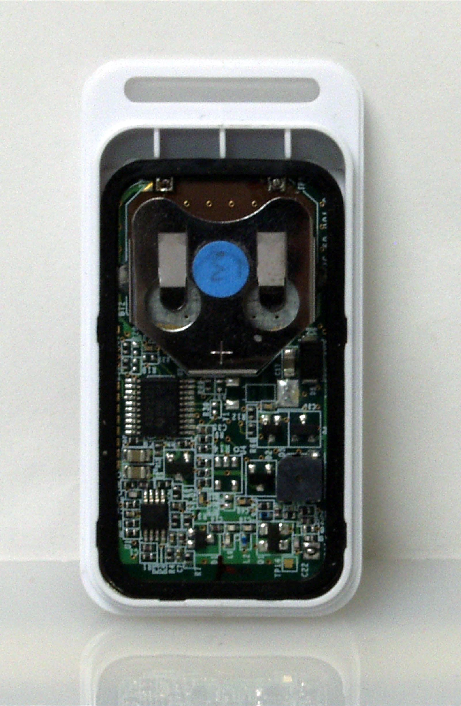
S9PKF460
Dec 12, 2006Key Chain Remote Control
Equipment Class
DSR - Part 15 Remote Control/Security Device Transceiver