S9PSNC1010Wireless Security Sensor
LifeShield, Inc.
Click to zoom
Application Details
- Equipment Class
- DSC - Part 15 Security/Remote Control Transmitter
- Date of Grant
- Feb 09, 2011
- Application Purpose
- Original Equipment
- Date of Application
- Feb 09, 2011
- Equipment Note
- Wireless Security Sensor
- Frequency Range
- 345.00000000 - 345.00000000
- Company
- LifeShield, Inc.
- Country
- United States
Documents & Files
Document Text
Text extracted from the exhibit documents filed with the FCC. Open a document above to read the original.
Users Manual
Sensor Installation Instructions Model SNC1010 Test Sensors Sensors should be tested to make sure they are installed and working properly. To test the Sensor installation: • With the system disarmed, open the door or window. This separates the Sensor and Magnet and notifies the system. You will also hear a chime each time you open and close your door or window. NOTE: MOVING THE GRID EXTENDER OR CONSOLE COULD DISRUPT THE INSTALLATION OF PREVIOUSLY INSTALLED SENSORS. THE SYSTEM WILL BEGIN TO BEEP IF A SENSOR IS NO LONGER WITHIN RANGE OF A GRID CONTROLLER AND THE DISPLAY WILL INDICATE THE NAME OF THE SENSOR THAT IS OUT OF RANGE. NOTE: Add a Grid Controller: If a beep results indicating a Sensor is out of range, you may need to add a Grid Extender or Console for additional range. If these retry solutions do not work, call LifeShield Customer Support for assistance at 1-888-392-2044 FCC Information FCC Part 15 This device complies with Part 15 of the FCC Rules. Operation is subject to the following two conditions: (1) This device may not cause harmful interference, and (2) this device must accept any interference received, including interference that may cause undesired operation. CAUTION: Changes and modifications to this product not expressly approved by LifeShield, Inc. could void not only the user’s authority to operate this device, but also the limited warranty. LIFESHIELD LIMITED WARRANTY FOR PRODUCTS AND ACCESSORIES PURCHASED IN THE UNITED STATES OR CANADA WHAT IS COVERED UNDER THIS WARRANTY Subject to the limitations and exclusions contained below, LifeShield, Inc. (“LifeShield”) warrants the LifeShield-branded (including all embedded software) sold by LifeShield for use with the LifeShield Home Security System (the “Products”) to be free from defects in materials and workmanship under normal consumer usage and in accordance with the accompanying instructions and documentation, for the period(s) set forth below. This warranty extends only to the first consumer purchaser, and is not transferable. LifeShield, at its option, will at no charge repair, replace or refund the purchase price of any Products that do not conform to this limited warranty. We may use functionally equivalent reconditioned/refurbished/pre-owned or new Products or parts and we may retain all replaced Products or parts. No data added to your Products, including but not limited to component names and system preferences, will be reinstalled. This limited warranty is the consumer’s exclusive remedy, and applies to new Products purchased by consumers in the United States or Canada, which are accompanied by this written warranty. PRODUCTS COVERED/LENGTH OF COVERAGE (the “Warranty Period”) New Products: One (1) year from the date of purchase by the first consumer purchaser of the Product. Products That Are Repaired or Replaced. The balance of the original warranty or for ninety (90) days from the date returned to the consumer, whichever expires later. Batteries. Only batteries whose fully charged capacity falls below 80% of their rated capacity and batteries that leak are covered by this limited warranty. HOW TO OBTAIN WARRANTY SERVICE OR OTHER INFORMATION To obtain service or information, please call: LifeShield Customer Service at: 1-888-392-2044 Or email us at: [email protected] You will receive instructions on how to ship the Products, at your expense, to a LifeShield Authorized Repair Center. To obtain service, you must include: a) a copy of your receipt, bill of sale or other comparable proof of purchase b) a written description of the problem c) the complete physical address of the location where the system was installed and most importantly d) your address and telephone number and, e) the “Return Merchandise Authorization” or “RMA” number that LifeShield provides to you WHAT IS NOT COVERED (EXCLUSIONS) Normal Wear and Tear. Periodic repair and replacement of parts due to normal wear and tear are excluded from coverage. Ornamental Decorations. Ornamental decorations, such as emblems and graphics and other decorative elements, are excluded from coverage. Abuse & Misuse. Defects or damage that result from the following are excluded from coverage: a) improper operation, storage, misuse or abuse, accident or neglect, such as physical damage (cracks, scratches, etc.) to the surface of the Product; b) contact with moisture, liquids, water, rain, extreme humidity, heavy perspiration or makeup, sand, dirt or the like, food, or proximity to or exposure to heat or cold, fire, flood, or lightning; c) other acts which are inconsistent with the instructions and documentation that accompany the Products; and d) use of the Products with any system other than the LifeShield Home Security System. Use of Non-LifeShield Products and Accessories. Defects or damage that result from the use of Non-LifeShield branded or certified products, accessories, software or other peripheral equipment are excluded from coverage, including without limitation defects or damage to Products that result from such use are excluded from coverage. Unauthorized Service or Modification. Defects or damages resulting from service, testing, adjustment, installation, maintenance, alteration, including without limitation, software changes, or modification in any way by someone other than LifeShield, or its authorized agents, are excluded from coverage. Altered Products. Products with the following characteristics are excluded from coverage: a) serial numbers or date tags that have been removed, altered or obliterated; b) broken seals or Products that show evidence of tampering; c) mismatched board serial numbers; or d) nonconforming or non-LifeShield housings, antennas, or parts. Communication Services. Defects, damages, or the failure of Products due to any communication service or signal not provided directly by LifeShield is excluded from coverage. Out of Warranty Products. Defects or damages reported to LifeShield after the Warranty Period are excluded fr…
Text truncated - open the document above for the full version.
Test Report
LifeShield, Inc. FCC ID: S9PSNC1010 Certification Test Report 2011-02-03 1.Introduction Model SNC1010 is a small battery-powred sensor/transmitter for use in a wireless alert system. See “opera- tional description.pdf” for more details on the device. Certification is requested under FCC Rules, Part 15, Subpart C, Paragraph 15.231. 2.Statement of Compliance Specific sections of FCC Rules Part 2 that require information or listing are given below. 2.1.FCC Part 2 §2.907 This is an application for certification of original equipment 2.2.FCC Part 2 §2.911 a)This application has been filed electronically using form 731. b)All required information has been supplied in this application and its attachments. c)This applicant has signed the application electronically. d)The technical test data has been signed by the agency performing the testing. e)Signature supplied in appropriate block on form 731. f)Processing fee has been paid by credit card. g)Signatures have been supplied electronically. 2.3.FCC Part 2 §2.913 a)This application has been filed electronically. b)Appropriate fees have been filed electronically. c)Equipment samples shall be supplied as requested. 2.4.FCC Part 2 §2.915 We are requesting a grant of certification. This application shows compliance with the technical standards. 2.5.FCC Part 2 §2.925 A label shall be affixed to each piece of equipment, showing the FCC identifier. The label shall read “FCC ID: S9PSNC1010”. Exhibit “Label.pdf” shows the label and location on the device. External and internal photos are provided in exhibits “External Photos.pdf” and “Internal Photos.pdf”. 2.6.FCC Part 2 §2.943, 2.945 Sample production equipment shall be submitted to the FCC upon request. 2.7.FCC Part 2 §2.947 a)Measurement procedure follows ANSI C63.4 version 2003 b)A description of utilized test equipment is contained in attached “Radiated Data.pdf”. 2.8.FCC Part 2 §2.948 Radiated measurements were taken at the following FCC-approved facility: Underwriters Laboratories, Inc. 1285 Walt Whitman Rd. Melville, NY 11747 Bob DeLisi Sr. Staff Engineer [email protected] phone 631-546-2452 fax 631-439-6752 See exhibit “Test Setup Photo.pdf” for a photo of the test site. 2.9.FCC Part 2 §2.1033 a. Form 731 has been filed electronically. b. The technical report, along with its exhibits, contains the information as follows: 1. Full name and mailing address of the manufacturer of the device and the applicant for certification: LifeShield, 770 Township Line Road, Suite 350, Yardley, PA 19067, USA 2. FCC Identifier is S9PSNC1010 3. Copy of the installation/user instructions is furnished in exhibit “Product Manual.pdf” 4. A brief description of the device and operation is furnished in exhibit “Operational Description.pdf”. 5. Block diagram is furnished in exhibit “Block Diagram.pdf”. Schematic is furnished in exhibit “Schematic.pdf”. 6. This document constitutes a technical test report. 7. Internal photographs are furnished in exhibit “Internal Photos.pdf”. External photographs are furnished in exhibit “External Photos.pdf”. 8. Not applicable. There are no peripheral or accessory devices used with this device. It is a standalone device. 9. This application not pursuant to the transition rules of section 15.37 10. Not applicable. This device does not include a scanning receiver. 11. Not applicable 12. Not applicable c. Not applicable. This device shall operate under Part 15 of the rules. d. Not applicable. e. Not applicable. This is not a composite system. 3.Discussion of Laboratory Measurements and Rules Compliance All measurement procedures follow ANSI C63.4 version 2003 Conducted Measurements: Conducted measurements were made using an Hewlett Packard Model 8594E spectrum analyzer with calibration due date 12/22/2011. Emissions Measurements: Radiated emission measurement equipment is detailed in attached “Radiated Data.pdf”. Description of the testing method and approach for maximizing emissions is contained in “Radiated Data.pdf”. 3.1.FCC Part 15 §15.231(a)(1) The device transmits packets when the inputs are triggered. A microcontroller monitors the input for activations and transmits 12 data packets when valid activations are detected. Packets are 26ms in duration . Precautions are taken in the firmware to ensure that transmitted packets are limited to one packet in any 100ms period. 3.2.FCC Part 15 §15.231(a)(2) A plot of the transmissions is shown following. This plot shows the transmissions occurring in a 5-second window as a result of one activation. The packets are shown to conclude within the 5-second window. 3.3.FCC Part 15 §15.231(a)(3) In the absence of external activations, a set of 6 supervision transmissions is sent once per hour. Therefore, the total on time for the supervisory messages is [6]x[26 ms] = [156ms]. This is well under the allowed 2000 ms per hour. 3.4.FCC Part 15 §15.231(a)(4) While this device is used in a security application, it does not continue transmitting beyond the packets resulting from each activation. 3.5.FCC Part 15 §15.231(a)(5) While this device is used in a security application, there is no setup information transmitted with this device. 3.6.FCC Part 15 §15.231(b) 3.6.1.Raw Field Strength Limits Interpolation performed on the data in the §15.231(b) table yields raw field strength limits as follows: Fundamental: 77.25 dBuV/m (77.25 = 20 * Log10(3750 + (345-260) * (12500-3750)/(470-260))) Spurious: 57.25 dBuV/m Certain harmonics of the transmitted signal fall in the restricted bands of §15.205. These harmonics are all above 960MHz and have the following limit as given in §15.209: Restricted band limit = 500uV/m = 54dBuV/m. 3.6.2.Duty Cycle Correction Factor and Resulting Limits This transmitter uses ASK modulation. 96 bits are transmitted in each packet, and the “on” time for each bit is 130 microseconds. The resulting “on” time per packet is 12.97ms. The transmitted packets are limited to one packet in a 100ms period. The transmitter duty cycle over a 100ms …
Text truncated - open the document above for the full version.
Test Report
Job Number: 11U13609 Model Number: SNC1010 Client Name: LifeShield Inc. FCC ID: S9PSNC1010 Underwriters Laboratories Inc. 1285 Walt Whitman Rd. Melville, New York 11747 USA Tel.: 631 271-6200 Fax: 631 439-6095 Rev. No 1.0 EMC Report 2010-87-EM-F0042 Engineering Test Data Only Test Lab: Bob DeLisi Sr. Staff Engineer 1285 Walt Whitman Rd. Melville, NY 11747 [email protected] 631-546-2452 631-439-6752 Applicant: LifeShield, Inc. 770 Township Line Rd., Suite 350 Yardley, PA 19067 Data Sign-Off The information contained within this data report reflect the item tested. The duty cycle correction factor applied within was supplied by the applicant and not verified by Underwriters Laboratories Inc. Test Engineer: Reviewer: Bob DeLisi (Ext.22452) Mike Antola(Ext.23053) Senior Staff Engineer Senior Project Engineer International EMC Services International EMC Services Conformity Assessment Services- Conformity Assessment Services Job Number: 11U13609 Model Number: SNC1010 Client Name: LifeShield Inc. FCC ID: S9PSNC1010 Underwriters Laboratories Inc. 1285 Walt Whitman Rd. Melville, New York 11747 USA Tel.: 631 271-6200 Fax: 631 439-6095 Rev. No 1.0 EMC Report 2010-87-EM-F0042 1.1 Test Conditions and Results – RADIATED EMISSIONS Test Description Measurements were made in a 10-meter semi-anechoic chamber that complies to CISPR 16/ANSI C63.4:2003. Preliminary (peak) measurements were performed at an antenna to EUT separation distance of 3-meters below 1GHz and at a separation distance of 4-meters above 1GHz. The results above 1GHz are corrected by 2.5dB to account for the 1-meter distance in distance between the distance the limits are specified at and the measurement distance. The EUT was rotated 360° about its azimuth with the receive antenna located at various heights in both horizontal and vertical polarities. Final measurements (peak, quasi- peak or average as noted) were then performed by rotating the EUT 360° and adjusting the receive antenna height from 1 to 4-meters. All frequencies were investigated in both horizontal and vertical antenna polarity, where applicable. Basic Standard FCC Part 15, Subpart C, 15.35, 15.209, 15.231 UL LPG 80-EM-S0029 Frequency range Measurement Point Fully configured sample scanned over the following frequency range 30 MHz – 1GHz (3 meter measurement distance) 1 - 3.5GHz (4 meter measurement distance) Limits Frequency (MHz) Limit (dBμV/m) Quasi-Peak Average General Emissions Fundamental Spurious 0.009 – 0.490 128.5 – 93.8 - - 0.490 – 1.705 73.8 – 63 - - 1.705 – 30 69.5 - - 30 – 88 40 - - 88 – 216 43.5 - - 216-960 46 - - 960-1000 54 - - 1000-3500 - - 54 (in restricted bands) 345 Fundamental - 77.2 - Harmonics of the Fundamental 345 - - 57.2 Supplementary information: Spurious limits are only applied against products of the transmitter. All other emissions must meet the general limits. The EUT was investigated in 3 axes to determine the worst case emissions. The worst case emissions were noted in the X-axis and reported within. Emissions below 30MHz were not investigated as the fundamental lies above 30MHz. Job Number: 11U13609 Model Number: SNC1010 Client Name: LifeShield Inc. FCC ID: S9PSNC1010 Underwriters Laboratories Inc. 1285 Walt Whitman Rd. Melville, New York 11747 USA Tel.: 631 271-6200 Fax: 631 439-6095 Rev. No 1.0 EMC Report 2010-87-EM-F0042 Table 1 Radiated Emissions EUT Configuration Settings Power EUT Configuration EUT Operation 3Vdc battery Stand-alone Continuous Transmit Supplementary information: None Table 2 Radiated Emissions Test Equipment Test Equipment Used Description Manufacturer Model Identifier Cal Date Cal Due Date 30-1000MHz EMI Receiver Rohde & Schwarz ESIB40 34968 2010-02-22 2011-02-22 Bicon Antenna Schaffner VBA6106A 43441 2010-09-09 2011-09-09 Log-P Antenna Schaffner UPA6109 44067 2010-04-26 2011-04-26 Switch Driver HP 11713A ME7A-627 N/A N/A System Controller Sunol Sciences SC99V 44396 N/A N/A Camera Controller Panasonic WV-CU254 44395 N/A N/A RF Switch Box UL 1 44398 N/A N/A Measurement Software UL Version 9.3 44740 N/A N/A Temp/Humidity/Pressure Meter Cole Parmer 99760-00 4268 2010-12-07 2012-12-07 Multimeter Fluke 83III ME5B-305 2010-02-01 2011-02-01 Above 1GHz (Band Optimized System) Spectrum Analyzer Agilent E7405A 19695 2010-02-01 2011-02-01 Horn Antenna (1-2 GHz) ETS 3161-01 51442 2008-03-28 See * below Horn Antenna (2-4 GHz) ETS 3161-02 48107 2007-09-27 See * below Signal Path Controller HP 11713A 50250 N/A N/A Gain Controller HP 11713A 50251 N/A N/A RF Switch / Preamp Fixture UL BOMS1 50249 N/A N/A System Controller UL BOMS2 50252 N/A N/A Measurement Software UL Version 9.3 44740 N/A N/A Temp/Humidity/Pressure Meter Cole Parmer 99760-00 43734 2009-11-11 2010-11-11 Multimeter Fluke 83III ME5B-305 2010-02-02 2011-02-02 * Note: As allowed by the calibration standard ANSI C63.4 Section 4.4.2, standard gain horns need only a one- time calibration. Only if physical damage occurs will the horn antenna require re-calibration. Gain standard horn antennas (sometimes called standard gain horn antennas) need not be calibrated beyond that which is provided by the manufacturer unless they are damaged or deterioration is suspected, or they are used at a distance closer than 2D2/ λ. Gain standard horn antennas have gains that are fixed by their dimensions and dimensional tolerances. Job Number: 11U13609 Model Number: SNC1010 Client Name: LifeShield Inc. FCC ID: S9PSNC1010 Underwriters Laboratories Inc. 1285 Walt Whitman Rd. Melville, New York 11747 USA Tel.: 631 271-6200 Fax: 631 439-6095 Rev. No 1.0 EMC Report 2010-87-EM-F0042 Figure 2 Radiated Emissions Graph Job Number: 11U13609 Model Number: SNC1010 Client Name: LifeShield Inc. FCC ID: S9PSNC1010 Underwriters Laboratories Inc. 1285 Walt Whitman Rd. Melville, New York 11747 USA Tel.: 631 271-6200 Fax: 631 439-6095 Rev. No 1.0 EMC Report 2010-87-EM-F0042 Table 3 Radiated Emissions Data Points LifeShield Inc. Transmitter Model: SNC 1010 Mode: Tx Job: Battery Powered Tested by: DC Test Me…
Text truncated - open the document above for the full version.
Test Setup Photos
Job Number: 11U13609 Model Number: SNC1010 Client Name: LifeShield Inc. FCC ID: S9PSNC1010 Underwriters Laboratories Inc. 1285 Walt Whitman Rd. Melville, New York 11747 USA Tel.: 631 271-6200 Fax: 631 439-6095 Rev. No 1.0 EMC Report 2010-87-EM-F0042
Contact Information
Applicant
Louis Stilp(President)
Technical Contact
Resolution Engineering, Inc.Rob Hendrickson
226 Locust Street · Hudson, Wisconsin · United States
Test Firm
UL LLCRick Titus
Technical Specifications
| # | Rule Parts | Frequency Range | Power Output |
|---|---|---|---|
| 1 | 15.231 | 345 MHz - 345 MHz | - |
Other Applications from LifeShield, Inc.
S9PSDC1001
Nov 14, 2012wireless sensor
Equipment Class
DSC - Part 15 Security/Remote Control Transmitter
S9PBSC1001
Mar 21, 2011BSC1001 Base Unit
Equipment Class
DSS - Part 15 Spread Spectrum Transmitter
S9PHSC1000
Aug 07, 2007Wireless Grid Controller
Equipment Class
DSS - Part 15 Spread Spectrum Transmitter
S9PKPC1000
Jun 19, 2007Wireless Security System Keypad
Equipment Class
DSS - Part 15 Spread Spectrum Transmitter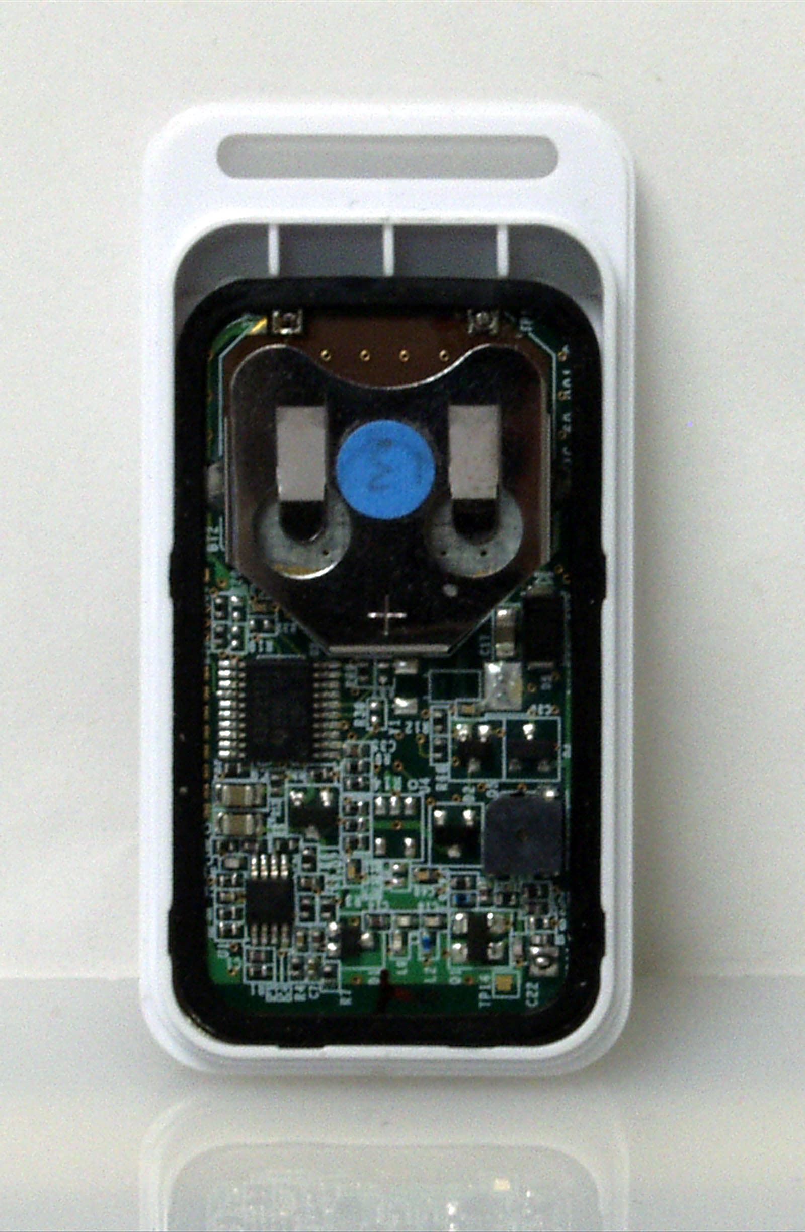
S9PKF460
Dec 12, 2006Key Chain Remote Control
Equipment Class
DSR - Part 15 Remote Control/Security Device Transceiver