S9PKPC1000Wireless Security System Keypad
LifeShield, Inc.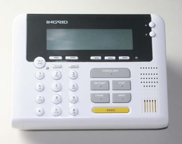
Click to zoom
Application Details
- Equipment Class
- DSS - Part 15 Spread Spectrum Transmitter
- Date of Grant
- Jun 19, 2007
- Application Purpose
- Original Equipment
- Date of Application
- Jun 19, 2007
- Equipment Note
- Wireless Security System Keypad
- Frequency Range
- 2401.47000000 - 2482.71000000
- Company
- LifeShield, Inc.
- Country
- United States
Documents & Files
Document Text
Text extracted from the exhibit documents filed with the FCC. Open a document above to read the original.
Users Manual
Console Installation Instructions Model: KPC1000 Console Kit InGrid Console Kit Contents KPC1000 InGrid Console PSC0101 Power Supply IG180 Ni-MH Rechargeable Battery Pack Phone Cord; Long Phone Cord; Short Table Stand Wall Plate & 2 Screws Determine the Location The Console may be used on a table top or mounted to the wall on a telephone wall plate near a wall outlet. Install the Console Install Battery Pack – The battery pack is shipped packed inside the Console, but it is not connected. Open the battery compartment and remove battery a. Insert the battery plug into the two-pin jack, and insert the battery. b. Replace the battery cover. Install the Console Table Top Use – If installing the Console on a table top, perform the following steps. a. Connect power supply to the back of the Console. b. Connect the long phone cable to the back of the Console. c. Route the wires up through the channel toward the top of the Console. d. Snap the table stand provided in the kit to the bottom of the Console. e. Connect the free end of the telephone cable to the wall phone jack. f. Plug the power supply into nearby electrical wall outlet that is not controlled by a switch. Wall Mounting – If mounting the Console to a wall, perform the following steps. a. Screw the Console mounting plate to the back of the Console. b. Connect power supply to the bottom of the Console. c. Connect phone cable to the bottom of the Console. d. Route the wires through the channel of the Console mounting plate. e. Connect the phone cord to the wall phone jack. f. Slide the Console with mounting plate onto the phone wall plate. g. Plug the power supply into nearby electrical wall outlet that is not controlled by a switch. CAUTION RISK OF EXPLOSION IF BATTERY IS REPLACED BY AN INCORRECT TYPE. DISPOSE OF USED BATTERIES ACCORDING TO THE INSTRUCTIONS. Add the Console to your InGrid System After the initial installation of the InGrid System, components may be added to enhance access or performance. These devices may be added to the InGrid System up to the number shown in the table: Device Device Maximum System Maximum Handsets 6 Consoles 4 9* Grid Extenders 4 *The system will allow a maximum of 9 Handset/Console or Grid Extender combinations. After the hardware is hooked up, use a Handset or Console that is currently registered on the System to enter the Security Menu and follow the steps for installing new hardware. Enter the Security Menu After installing the hardware, enter Menu on your Handset or Console. o Scroll to Security Setup and press SELECT o Enter Code and press SELECT . Add the Console On your existing Handset or Console, navigate to GC or Handset (Menu/Security Setup/GC or Handset/<Add New>). 1. Press the SELECT key to <Add New>. The system will begin searching for the new Handset or Console you are looking to add. Note: o Use only InGrid IG180 rechargeable battery packs supplied with your various Home Protection components. o Replacement battery packs are also available through the InGrid’s customer service at 1-877-INGRID7 or on-line at www.InGridHome.comUse only the supplied AC power adapter. Do not use any other adapter. o Place the power cord so that it does not create a trip hazard or where it could become pinched and create an electrical 2. On the New Handset or Console, press the SEARCH key. SEARCH Not Available 3. The system will inform you when it has found and added the Handset or Console via the display and an audio signal. Press OK when you have been informed that the Handset or Console has been added. 4. You will then be given the option to edit the default name. 5. Press OK. FCC Information FCC Part 15 This device complies with Part 15 of the FCC Rules. Operation is subject to the following two conditions: (1) This device may not cause harmful interference, and (2) this device must accept any interference received, including interference that may cause undesired operation. CAUTION: Changes and modifications to this product not expressly approved by InGrid, Inc. could void not only the user’s authority to operate this device, but also the limited warranty. Note: This equipment has been tested and found to comply with the limits for a Class B digital device, pursuant to Part 15 of the FCC Rules. These limits are designed to provide reasonable protection against harmful interference in a residential installation. This equipment generates, uses, and can radiate radio frequency energy and, if not installed and used in accordance with the instructions, may cause harmful interference to radio communications. However, three is no guarantee that interference will not occur in a particular installation. If this equipment does cause harmful interference to radio or television reception, which can be determined by turning the equipment off and on, the user is encouraged to try to correct the interference by one or more of the following measures: o Reorient or relocate the receiving antenna o Reorient or relocate and increase the separation between the equipment and receiver o Connect the equipment into an outlet on a circuit different from that to which the receiver is connected. Some cordless telephones operate at frequencies that may cause interference to nearby TVs or VCRs. To minimize or prevent such interference, the base or the cordless telephone should not be placed near or on top of a TV or VCR. If interference is experienced, move the cordless telephone further away from the TV or VCR. This will often reduce, or eliminate, interference. Consult an experienced radio/TV technician for help if these measures do not eliminate the interference. The antenna used with this product must be installed to provide a separation distance of at least 20 cm from all persons and must not be co-located or operating in conjunction with any other antenna or transmitter. This equipment should be serviced only by Ingrid, Inc. or its authorized agents. FCC Part 68 This equipment complies with Part 68 of the FCC rules and the …
Text truncated - open the document above for the full version.
External Photos
Exhibit 3 S9PKPC1000 Exterior Photos Page 1 of 2 Top View Exterior Bottom View Exhibit 3 S9PKPC1000 Exterior Photos Page 2 of 2 Side View Battery Door
ID Label/Location Info
Exhibit 1 S9PKPC1000 Label Details
Internal Photos
Exhibit 9 Ingrid Interior Photos S9PKPC1000 Page 1 of 2 Bottom View PCB w/Antenna Assembly Top View PCB w/Antenna Assembly 345 MHz Antenna 2.4 GHz Antennas 2.4 GHz Antennas 345 MHz Antenna Exhibit 9 Ingrid Interior Photos S9PKPC1000 Page 2 of 2 PCB/Antenna/Keypad Assembly
RF Exposure Info
Prediction of MPE limit at a given distance Equation from page 18 of OET Bulletin 65, Edition 97-01where: S = power density P = power input to the antennaG = power gain of the antenna in the direction of interest relative to an isotropic radiatorR = distance to the center of radiation of the antenna Maximum peak output power at antenna input terminal: 20.11 (dBm) Maximum peak output power at antenna input terminal: 102.5651926 (mW) Antenna gain(typical): 3 (dBi) Maximum antenna gain: 1.995262315 (numeric) Prediction distance: 20 (cm) Prediction frequency: 2401.048077 (MHz) MPE limit for uncontrolled exposure at prediction frequency: 1.600698718 (mW/cm^2) Power density at prediction frequency: 0.040713 (mW/cm^2) 0.407127 (W/m^2) Maximum allowable antenna gain: 18.94579452 (dBi) Margin of Compliance: 15.94579452 dB 2 4 R PG S π =
Test Report
www.nemko.com FCC Part 15 Subpart C, 15.247 : October 2006 Test Report: 83533-3R1TRFWL Applicant: Ingrid Inc. 920 Cassatt Rd. Suite 220 Berwyn, PA 19312 USA Apparatus: KPC1000 FCC ID: S9PKPC1000 In Accordance With: FCC Part 15 Subpart C, 15.247 FHSS System and Digitally Modulated Radiators 902-928MHz, 2400 - 2483.5 MHz, 5725-5850MHz Tested By: Nemko Canada Inc. 303 River Road Ottawa, Ontario K1V 1H2 Authorized By: Jason Nixon, Telecom Specialist Date: May 15, 2007 Total Number of Pages: 30 Nemko Canada Inc. REPORT SUMMARY Report Number: 83533-3R1TRFWL FCC ID: S9PKPC1000 Specification: FCC Part 15 Subpart C, 15.247 Page 2 of 30 Report Summary These tests were conducted on a sample of the equipment for the purpose of demonstrating compliance with Part 15, Subpart C. Radiated tests were conducted in accordance with ANSI C63.4-2003. Radiated emissions are made on an open area test site. A description of the test facility is on file with the FCC. The assessment summary is as follows: Apparatus Assessed: KPC1000 Specification: FCC Part 15 Subpart C, 15.247 Compliance Status: Complies Exclusions: None Non-compliances: None Report Release History: Original Release Author: Heng Lin EMC / Wireless Specialist Note that the results contained in this report relate only to the items tested and were obtained in the period between the date of initial receipt of samples and the date of issue of the report. This test report has been completed in accordance with the requirements of ISO/IEC 17025. Nemko Canada Inc. authorizes the applicant to reproduce this report provided it is reproduced in its entirety and for use by the company’s employees only. Any use which a third party makes of this report, or any reliance on or decisions to be made based on it, are the responsibility of such third parties. Nemko Canada Inc. accepts no responsibility for damages, if any, suffered by any third party as a result of decisions made or actions based on this report. Nemko Canada Inc. REPORT SUMMARY Report Number: 83533-3R1TRFWL FCC ID: S9PKPC1000 Specification: FCC Part 15 Subpart C, 15.247 Page 3 of 30 TABLE OF CONTENTS Report Summary......................................................................................................................................... 2 Section 1 : Equipment Under Test............................................................................................................. 4 1.1 Product Identification .................................................................................................................................4 1.2 Samples Submitted for Assessment............................................................................................................4 1.3 Technical Specifications of the EUT ..........................................................................................................4 Section 2 : Test Conditions......................................................................................................................... 5 2.1 Specifications .............................................................................................................................................5 2.2 Deviations From Laboratory Test Procedures ............................................................................................5 2.3 Test Environment .......................................................................................................................................5 2.4 Test Equipment...........................................................................................................................................5 Section 3 : Observations ............................................................................................................................. 6 3.1 Modifications Performed During Assessment ............................................................................................6 3.2 Record Of Technical Judgements ...............................................................................................................6 3.3 EUT Parameters Affecting Compliance .....................................................................................................6 3.4 Test Deleted................................................................................................................................................6 3.5 Additional Observations .............................................................................................................................6 Section 4 : Results Summary ..................................................................................................................... 7 4.1 FCC Part 15 Subpart C : Test Results ........................................................................................................8 Appendix A : Test Results .......................................................................................................................... 9 Clause 15.207(a) Powerline Conducted Emissions ...............................................................................................9 Clause 15.209(a) Radiated Emissions within Restricted Bands ..........................................................................11 Clause 15.247(a)(1) Frequency hopping systems ................................................................................................15 Clause 15.247(a)(1)(iii) Frequency hopping systems operating in the 2400-2483.5 MHz band .........................16 Clause 15.247(b)(1) Maximum peak output power of Frequency hopping systems operating in the 2400-2483.5 MHz band and 5725-5850 MHz band ...........................................................................................................21 Clause 15.247(d) Radiated Emissions Not in Restricted Bands ..........................................................................24 Appendix B : Setup Photographs ...................................................…
Text truncated - open the document above for the full version.
Test Setup Photos
Conducted Emission at Mains Port Spurious Emissions Setup:
Contact Information
Applicant
Louis Stilp(President)
Technical Contact
IngridEd Dickinson
[email protected]484-913-1423
920 Cassatt Rd. · Berwyn, Pennsylvania · United States
Non-Technical Contact
IngridWilliam Brown
[email protected]484-913-1490
Test Firm
Nemko Canada Inc.Stuart Beck
Technical Specifications
| # | Rule Parts | Frequency Range | Power Output |
|---|---|---|---|
| 1 | 15C | 2.40 GHz - 2.48 GHz | 103.00 mW |
Other Applications from LifeShield, Inc.
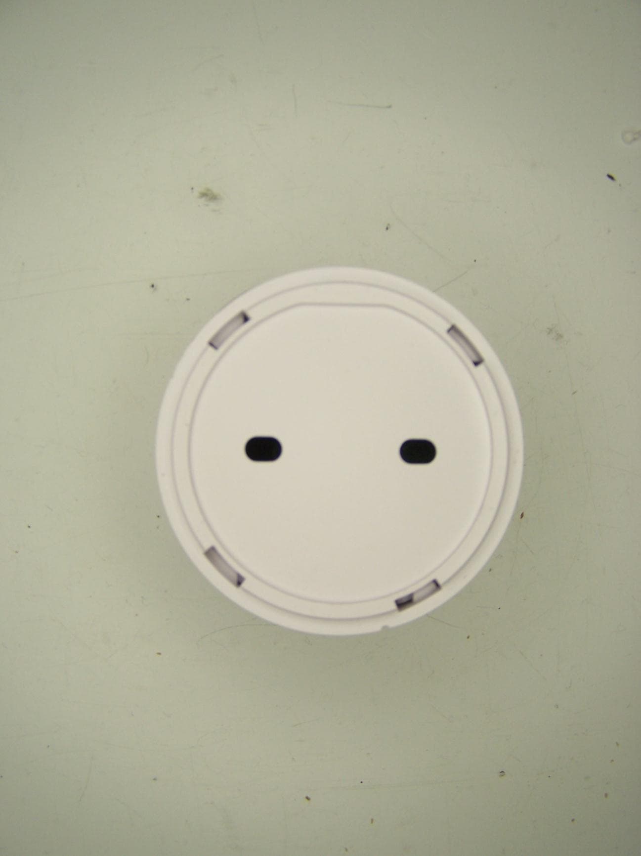
S9PSDC1001
Nov 14, 2012wireless sensor
Equipment Class
DSC - Part 15 Security/Remote Control Transmitter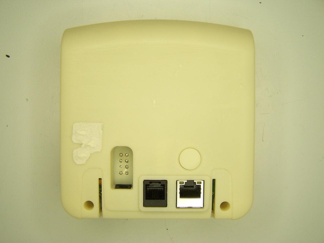
S9PBSC1001
Mar 21, 2011BSC1001 Base Unit
Equipment Class
DSS - Part 15 Spread Spectrum Transmitter
S9PSNC1010
Feb 09, 2011Wireless Security Sensor
Equipment Class
DSC - Part 15 Security/Remote Control Transmitter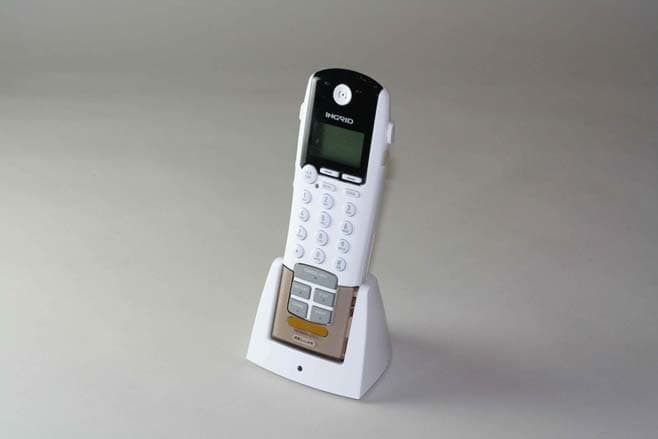
S9PHSC1000
Aug 07, 2007Wireless Grid Controller
Equipment Class
DSS - Part 15 Spread Spectrum Transmitter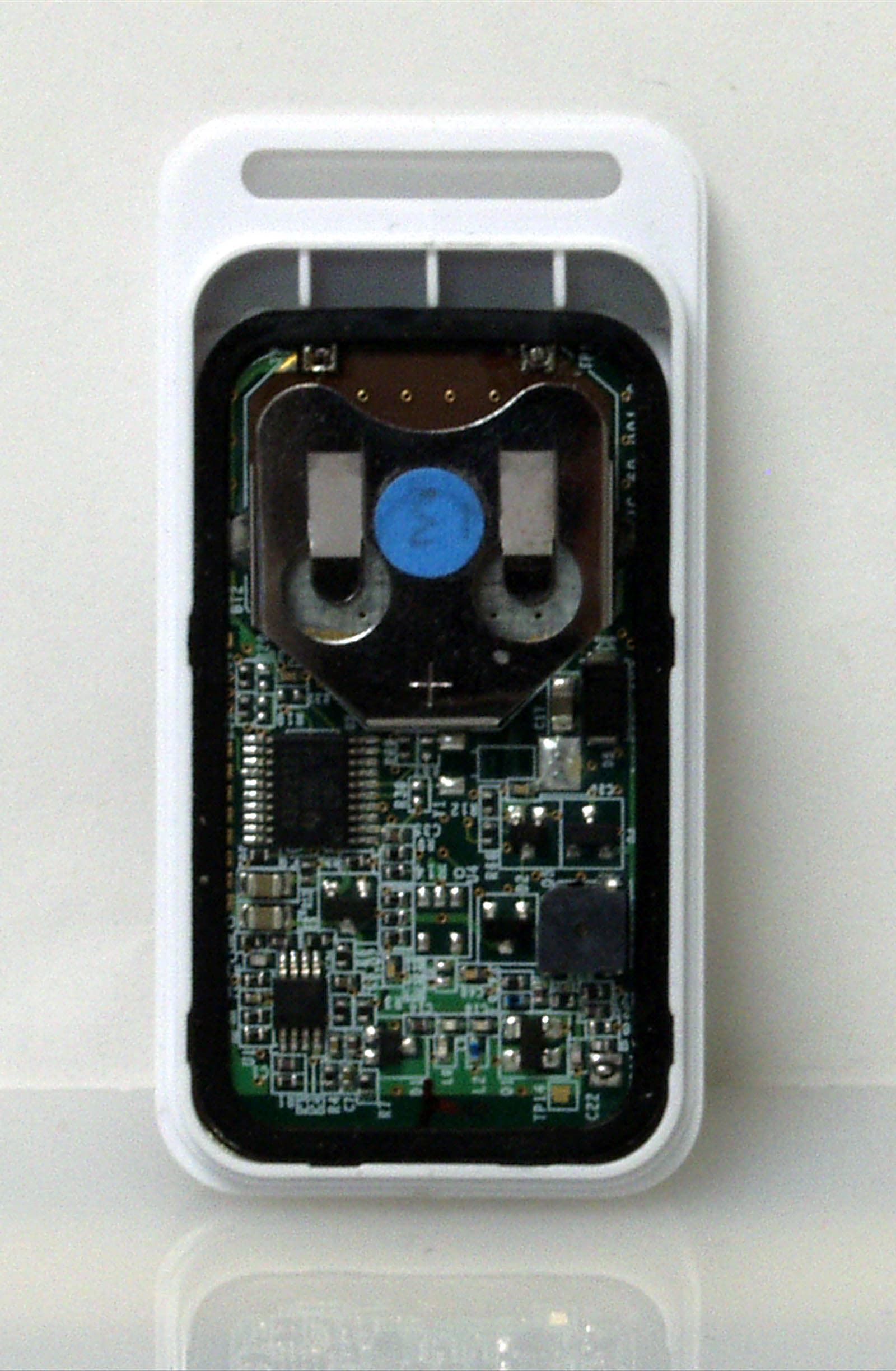
S9PKF460
Dec 12, 2006Key Chain Remote Control
Equipment Class
DSR - Part 15 Remote Control/Security Device Transceiver