S9ZTEW455APBOHigh Power Wireless Outdoor Access Point
TRENDNET, INC.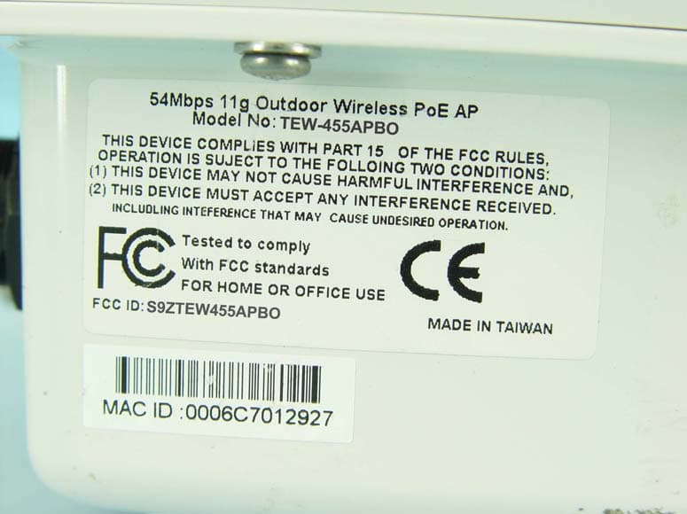
Click to zoom
Application Details
- Equipment Class
- DTS - Digital Transmission System
- Date of Grant
- Dec 06, 2007
- Application Purpose
- Original Equipment
- Date of Application
- Dec 06, 2007
- Equipment Note
- High Power Wireless Outdoor Access Point
- Frequency Range
- 2412.00000000 - 2462.00000000
- Company
- TRENDNET, INC.
- Country
- United States
Documents & Files
Document Text
Text extracted from the exhibit documents filed with the FCC. Open a document above to read the original.
Users Manual
Federal Communication Commission Interference Statement This equipment has been tested and found to comply with the limits for a Class B digital device, pursuant to Part 15 of the FCC Rules. These limits are designed to provide reasonable protection against harmful interference in a residential installation. This equipment generates, uses and can radiate radio frequency energy and, if not installed and used in accordance with the instructions, may cause harmful interference to radio communications. However, there is no guarantee that interference will not occur in a particular installation. If this equipment does cause harmful interference to radio or television reception, which can be determined by turning the equipment off and on, the user is encouraged to try to correct the interference by one of the following measures: -Reorient or relocate the receiving antenna. -Increase the separation between the equipment and receiver. -Connect the equipment into an outlet on a circuit different from that towhich the receiver is connected. -Consult the dealer or an experienced radio/TV technician for help. FCC Caution: Any changes or modifications not expressly approved by the party responsible for compliance could void the user's authority to operate thisequipment. This device complies with Part 15 of the FCC Rules. Operation is subject to the following two conditions: (1) This device may not cause harmful interference, and (2) this device must accept any interference received, including interference that may cause undesired operation. IMPORTANT NOTE: FCC Radiation Exposure Statement: This equipment complies with FCC radiation exposure limits set forth for an uncontrolled environment. This equipment should be installed and operated with minimum distance20cm between the radiator & your body. This transmitter must not be co-located or operating in conjunction with any other antenna or transmitter. The availability of some specific channels and/or operational frequency bands are country dependent and arefirmware programmed at the factory to match the intended destination. The firmware setting is not accessible by the end user. European Union Notice: Radio products with the CE marking comply with the R&TTE Directive (1999/5/EC). Compliance with these directives implies conformity to the following European Norms: ◆EN 60950-1:2001+A11:2004 Product Safety ◆EN 300 328 Technical requirement for radio equipment ◆EN 301 489-1/-17 General EMC requirements for radio equipment ◆EN 50385 Contents 1INTRODUCTION.......................................................................................1 THEPRODUCT..............................................................................................1 KEYFEATURES.............................................................................................1 2PACKAGE CONTENTS...............................................................................2 CONTENT OFPACKAGE.....................................................................................2 SYSTEMREQUIREMENTS FORCONFIGURATION...........................................................2 3CONNECTION(HARDWARE)......................................................................3 FRONT/INTERFACEVIEW..................................................................................3 REAR/SIDE VIEW...........................................................................................3 4BASIC IP NETWORKING............................................................................8 WIRELESSLANBASICS....................................................................................9 5GETTING STARTED................................................................................11 6CONFIGURATION MENU..........................................................................11 BASICSITESURVEY...................................................................................12 BASICADMINISTRATION..............................................................................12 BASICIPCONFIGURATION............................................................................13 BASICOPERATIONMODE.............................................................................13 ADVANCEDRADIOSETTING..........................................................................15 ADVANCEDSECURITYSETTING.......................................................................16 WPA-PSKSECURITY....................................................................................17 WPASECURITY..........................................................................................17 ADVANCEDMACADDRESSCONTROL...............................................................18 ADVANCEDPROTOCOLFILTER.......................................................................18 ADVANCEDSNMPCONFIGURATION.................................................................19 ADVANCEDMISCELLANEOUS.........................................................................20 STATUSASSOCIATIONSTATUS........................................................................21 SUPERUSER..............................................................................................21 FIRMWAREUPGRADE....................................................................................22 FIRMWAREVERSION.....................................................................................22 7OUTDOOR AP UTILITY INSTALLATION......................................................23 8OUTDOOR AP UTILITYUSER GUIDE..........................................................27 Pg1of26 1INTRODUCTION The Product The product is based on the IEEE 802.11b/gstandard, which is the latest 54Mbps Wireless LAN (WLAN) standard. Havingthiswireless protocols in one product ensure that your investments are protected, while enabling you to enjoy the fastest Wireless LAN speed. This productmodel–TEW-455APBOcould operate eitheras aWireless LAN Access Point or Ethernet Bridge mode. K…
Text truncated - open the document above for the full version.
Users Manual
Pg22of30 StatusFirmware Upgrade This page allows you to update the firmware (software) intheAP. New firmwareare issued to improve the performance and add featuresto the product. The new firmware will be name “apimg1”. 1.Save the file in your PC. 2.Browse to the file with the name “apimg1”. 3.Click onUpload. 4.ReboottheAPand the process is complete. 5.After reboot perform a default factory setting. Do not change the filename of the new firmware. New firmware with filename other than “apimg1” will cause the process to fail. StatusFirmware Version This page presents information of the firmware version oftheAP. Pg23of30 7OUTDOORAPUTILITYINSTALLATION Introduction TheOutdoor APutility is an easy-to-use software that allows an Administrator to quickly configure theAPat first boot-up. The QS Utility only communicates with authorized Access Points and Bridge. The Utility allows the devices to be monitored and configured even if they all have the same default IP Address at first boot-up after installation. PC Requirement X86 based CPU, 600Mhz & above 128 MB RAM 1.5 MB harddisk space Ethernet port / Wireless LAN adapter Windows 2000 and above WAN/Internet QS PC AP Wireless Client Pg24of30 Installation Step one Double click on the filesetup.exeand clickNextto continue. Step two ClickNextto accept the default installation directory. If you wish to change the installation directory, click on the Changebutton to select a new directory. Pg25of30 Step three ClickInstallto do the actual installation Pg26of30 Step four ClickFinishto exit the installation wizard. Pg27of30 8OUTDOORAPUTILITYUSERGUIDE Outdoor AP UtilityIcon Click on the desktop iconOutdoor AP Utilityto start the application. Parameters Display in Utility The Utility displays the following parameters that can be changed. 1.IP Address 2.Subnet Mask 3.Gateway 4.Device Name 5.Channel 6.DHCP/Static IP Username and Password of Utility If the username/password of the Devices have been changed,the QS Utility has to be updated with the correct username and password. If the username/password of the QS Utility and the Device is different, QS Utility will not operate as desire. Pg28of30 Making Changes The changes are directly applied in the Utility. It does not matter if all the devices have the same IP Address. The QS Utility identifies them uniquely by their MAC Addresses. Updating Changes After the necessary changes have been made, the Administrator can apply the changes totheAP. Check on theReboot Checkbox and click on theUpdatebutton to reboot the device. Multiple devices can be updated all at once. Use ctrl-left click to select multiple entries or type ctrl-A to select all entries. Click on Update button to begin the update process. To refresh the view, use theFindbutton. Pinging the Device The QS Utility can also be used to ping a selected Device to check the connectivity. Pg29of30 Professional installation instruction 1.Installation personal This product is designed for specific application and needs to be installed by a qualified personal who has RF and related rule knowledge. The general user shall not attempt to install or change the setting. 2. Installation location The product shall be installed at a location where the radiating antenna can be kept 20 cm from nearby person in normal operation condition to meet regulatory RF exposure requirement. 4. Installation procedure Please refer to user’s manual for the detail. 3. External antenna, Use only the antennas which have been approved byTRENDware International, Inc.. The non- approved antenna(s) may produce unwanted spurious or excessive RF transmitting power which may lead to the violation of FCC limit and is prohibited. . 5. Warning Please carefully select the installation position and make sure that the final output power does not exceed the limit set force in US Rule CFR 47 part 15 section 15.247 . The violation of the rule could lead to serious federal penalt. Pg30of30 Limited Warranty TRENDnet warrants its products against defects in material and workmanship, under normal use and service, for the following lengths of time from the date of purchase. TEW-455APBO3 years If a product does not operate as warranted above during the applicable warranty period, TRENDnet shall, at its option and expense, repair the defective product or deliver to customer an equivalent product to replace the defective item. All products that are replaced will become the property of TRENDnet. Replacement products may be new or reconditioned. TRENDnet shall not be responsible for any software, firmware, information, or memory data of customer contained in, stored on, or integrated with any products returned to TRENDnet pursuant to any warranty. There are no user serviceable parts inside the product. Do not remove or attempt to service the product through any unauthorized service center. This warranty is voided if (i) the product has been modified or repaired by any unauthorized service center, (ii) the product was subject to accident, abuse, or improper use (iii) the product was subject to conditions more severe than those specified in the manual. Warranty service may be obtained by contacting TRENDnet office within the applicable warranty period for a Return Material Authorization(RMA) number, accompanied by a copy of the dated proof of the purchase. Products returned to TRENDnet must be pre-authorized by TRENDnet with RMA number marked on the outside of the package, and sent prepaid, insured and packaged appropriately for safe shipment. WARRANTIES EXCLUSIVE: IF THE TRENDNET PRODUCT DOES NOT OPERATE AS WARRANTED ABOVE, THE CUSTOMER’S SOLE REMEDY SHALL BE, AT TRENDNET’S OPTION, REPAIR OR REPLACEMENT. THE FOREGOING WARRANTIES AND REMEDIES ARE EXCLUSIVE AND ARE IN LIEU OF ALL OTHERWARRANTIES, EXPRESSED OR IMPLIED, EITHER IN FACT OR BY OPERATION OF LAW, STATUTORY OR OTHERWISE, INCLUDING WARRANTIES OF MERCHANTABILITY AND FITNESS FOR A PARTICULAR PURPOSE. TRENDNET NEITHER ASSUMES NOR AUTHORIZES ANY OTHER PERSON TO…
Text truncated - open the document above for the full version.
Attestation Statements
TRENDware International, Inc. 20675 Manhattan Place, Torrance, CA 90501, U.S.A. Tel: 310-961-5500 Fax: 310-961-5511 DECLARATION LETTER Date: November 27, 2007 To whom it may concern: We, TRENDware International, Inc. declares that the device does not have “Ad Hoc on non-US frequencies” and/or “on DFS frequencies” while applying for the following product. Trademark: TRENDnet Model Name: TEW-455APBO Product Name: High Power Wireless Outdoor Access Point FCC ID: S9ZTEW455APBO If you have any questions regarding the authorization, please do not hesitate to contact us. Thank you! Sincerely yours, Wen Tsai/Sr. Product Manager TRENDware International, Inc. Tel: 310-961-5500 Fax: 310-961-5511 Email: [email protected]
Attestation Statements
TRENDware International, Inc. 20675 Manhattan Place, Torrance, CA 90501, U.S.A. Tel: 310-961-5500 Fax: 310-961-5511 Professional Installation Attestation Date: 11/28/2007 To Whom It May Concern: Please be advised that due to the unique function supplied by this product, this device is intended for wireless Access Point, bridge or repeater function, only and will be distributed through controlled distribution channel which has trained professional to install this product and will not be sold directly to the general public through retail store. Thank you for your attention. Sincerely yours, Wen Tsai/Sr. Product Manager TRENDware International, Inc. Tel: 310-961-5500 Fax: 310-961-5511 Email: [email protected]
Cover Letter(s)
TRENDware International, Inc. 20675 Manhattan Place, Torrance, CA 90501, U.S.A. TEL: (310) 961-5500; FAX: (310)961-5511 Date: Oct 10 th , 2007 FCC ID: S9ZTEW455APBO Federal Communications Commission Authorization and Evaluation Division Confidentiality Request Pursuant to Sections 0.457 and 0.459 of the Commission’s Rules, the Applicant hereby requests confidential treatment of information accompanying this Application as outlined below: Schematics Block Diagram The above materials contain trade secrets and proprietary information not customarily released to the public. The public disclosure of these matters might be harmful to the Applicant and provide unjustified benefits to its competitors. The Applicant understands that pursuant to Rule 0.457, disclosure of this Application and all accompanying documentation will not be made before the date of the Grant for this application. Sincerely yours, __________________________________________ Name: Wen Tsai Job Title: Sr. Product Manager Email : [email protected] TRENDware International Inc.
Cover Letter(s)
TRENDware International, Inc. 20675 Manhattan Place, Torrance, CA 90501, U.S.A. TEL: (310) 961-5500; FAX: (310)961-5511 Agency Authorization Letter Date: Oct 10 th , 2007 To whom it may concern: We, the undersigned, TRENDware International, Inc. hereby authorize Advance Data Technology Corp. (ADT) of Taiwan to act on our behalf, as our agent, in the following matters related to the FCC approval of our products: report submittal, related correspondence, the signing of all documents relating to these matters, and any other lawful activity necessary to obtain such certification. Any act carried out by ADT within the scope of this authorization shall have the same effects as our own. This authorization shall expire six months from the original date. If you have any questions regarding the authorization, please don’t hesitate to contact us. Thank you! Sincerely yours, ___________________________ Name: Wen Tsai Job Title: Sr. Product Manager TRENDware International Inc.
External Photos
Page 1 CONSTRUCTION PHOTOS OF EUT Page 2
Internal Photos
Page 4 Page 5 Page 6 Page 7 Page 8 Page 9 Page 10 Page 11
RF Exposure Info
FCC ID: S9ZTEW455APBO Report No: SA960524L14 1 RF EXPOSURE REPORT REPORT NO.: SA960524L14 MODEL NO.: AP-1062, GTT24GAP-OD01, TEW-455APBO ACCORDING: FCC Guidelines for Human Exposure IEEE C95.1 APPLICANT : TRENDware International, Inc. ADDRESS : 20675 Manhattan Place, Torrance, CA 90501, U.S.A. ISSUED BY : Advance Data Technology Corporation LAB ADDRESS : No. 47, 14 th Ling, Chia Pau Tsuen, Lin Kou Hsiang 244, Taipei Hsien, Taiwan, R.O.C. TEST LOCATION : No. 19, Hwa Ya 2 nd Rd., Wen Hwa Tsuen, Kwei Shan Hsiang, Taoyuan Hsien 333, Taiwan, R.O.C. FCC ID: S9ZTEW455APBO Report No: SA960524L14 2 RF EXPOSURE MEASUREMENT (MOBILE DEVICE) 1. INTRODUCTION In this document, we try to prove the safety of radiation harmfulness to the human body for our product. The limit for Maximum Permissible Exposure (MPE) specified in FCC 1.1310 is followed. The Gain of the antenna used in this product is measured in a Fully Anechoic Chamber (FAC) calibrated for antenna measurement in ADT, and also the maximum total power input to the antenna is measured. Through the Friis transmission formula and the maximum gain of the antenna, we can calculate the distance, away from the product, where the limit of MPE is reached. Although the Friis transmission formula is a far field assumption, the calculated result of that is an over-prediction for near field power density. We will take that as the worst case to specify the safety range. 2. RF EXPOSURE LIMIT According to FCC 1.1310: The criteria listed in the following table shall be used to evaluate the environmental impact of human exposure to radio-frequency (RF) radiation as specified in 1.1307(b) LIMITS FOR MAXIMUM PERMISSIBLE EXPOSURE (MPE) FREQUENCY RANGE (MHz) ELECTRIC FIELD STRENGTH (V/m) MAGNETIC FIELD STRENGTH (A/m) POWER DENSITY (mW/cm 2 ) AVERAGE TIME (minutes) (A)LIMITS FOR OCCUPATIONAL / CONTROL EXPOSURES 300-1500 ... ... F/300 6 1500-100,000 ... ... 5 6 (B)LIMITS FOR GENERAL POPULATION / UNCONTROLLED EXPOSURE 300-1500 ... ... F/1500 30 1500-100,000 ... ... 1.0 30 F = Frequency in MHz FCC ID: S9ZTEW455APBO Report No: SA960524L14 3 3. FRIIS FORMULA Friis transmission formula : Pd = (Pout*G) / (4*pi*r 2 ) where Pd = power density in mW/cm 2 Pout = output power to antenna in mW G = gain of antenna in linear scale Pi = 3.1416 R = distance between observation point and center of the radiator in cm If we know the maximum Gain of the antenna and the total power input to the antenna, through the calculation, we will know the MPE value at distance r. Ref.: David K. Cheng, Field and Wave Electromagnetics, Second Edition, Page 640, Eq. (11-133). 4. EUT OPERATING CONDITION The software provided by Manufacturer enabled the EUT to transmit and receive data at lowest, middle and highest channel individually. 5. CLASSIFICATION This device is fixed inside the host equipment. Warning statement to the user for keeping at least 20cm or more separation distance with the antenna should be included in users manual. So, this device is classified as Mobile Device. FCC ID: S9ZTEW455APBO Report No: SA960524L14 4 6. TEST RESULTS 6.1 ANTENNA GAIN The maximum Gain measured in Fully Anechoic Chamber is 9dBi or 7.943282(numeric) or 4.5dBi or 2.81838(numeric). 6.2 OUTPUT POWER INTO ANTENNA & RF EXPOSURE VALUE AT DISTANCE 20cm: FOR Antenna gain 9dBi 802.11b DSSS MODULATION CHANNEL CHANNEL FREQUENCY (MHz) PEAK POWER OUTPUT (mW) PEAK POWER OUTPUT (dBm) POWER DENSITY (mW/cm 2 ) LIMIT OF POWER DENSITY (mW/cm 2 ) 1 2412 18.113 12.58 0.029 1.0 6 2437 35.645 15.52 0.056 1.0 11 2462 20.277 13.07 0.032 1.0 802.11g OFDM MODULATION_NORMAL MODE CHANNEL CHANNEL FREQUENCY (MHz) PEAK POWER OUTPUT (mW) PEAK POWER OUTPUT (dBm) POWER DENSITY (mW/cm 2 ) LIMIT OF POWER DENSITY (mW/cm 2 ) 1 2412 12.853 11.09 0.020 1.0 6 2437 25.235 14.02 0.040 1.0 11 2462 15.922 12.02 0.025 1.0 802.11g OFDM MODULATION_TURBO MODE CHANNEL CHANNEL FREQUENCY (MHz) PEAK POWER OUTPUT (mW) PEAK POWER OUTPUT (dBm) POWER DENSITY (mW/cm 2 ) LIMIT OF POWER DENSITY (mW/cm 2 ) 6 2437 22.751 13.57 0.036 1.0 FCC ID: S9ZTEW455APBO Report No: SA960524L14 5 FOR Antenna gain 4.5dBi 802.11b DSSS MODULATION CHANNEL CHANNEL FREQUENCY (MHz) PEAK POWER OUTPUT (mW) PEAK POWER OUTPUT (dBm) POWER DENSITY (mW/cm 2 ) LIMIT OF POWER DENSITY (mW/cm 2 ) 1 2412 18.113 12.58 0.010 1.0 6 2437 35.645 15.52 0.020 1.0 11 2462 20.277 13.07 0.011 1.0 802.11g OFDM MODULATION_NORMAL MODE CHANNEL CHANNEL FREQUENCY (MHz) PEAK POWER OUTPUT (mW) PEAK POWER OUTPUT (dBm) POWER DENSITY (mW/cm 2 ) LIMIT OF POWER DENSITY (mW/cm 2 ) 1 2412 12.853 11.09 0.007 1.0 6 2437 25.235 14.02 0.014 1.0 11 2462 15.922 12.02 0.009 1.0 802.11g OFDM MODULATION_TURBO MODE CHANNEL CHANNEL FREQUENCY (MHz) PEAK POWER OUTPUT (mW) PEAK POWER OUTPUT (dBm) POWER DENSITY (mW/cm 2 ) LIMIT OF POWER DENSITY (mW/cm 2 ) 6 2437 22.751 13.57 0.013 1.0
Test Report
Report No.: RF960524L14 1 Report Format Version 2.0.6 FCC TEST REPORT REPORT NO.: RF960524L14 MODEL NO.: TEW-455APBO (refer to item 3.1 for more detail) RECEIVED: May 24, 2007 TESTED: Sep. 02 ~ Sep. 30, 2007 ISSUED: Oct. 09, 2007 APPLICANT : TRENDware International, Inc. ADDRESS : 20675 Manhattan Place, Torrance, CA 90501, U.S.A. ISSUED BY : Advance Data Technology Corporation LAB ADDRESS : No. 47, 14 th Ling, Chia Pau Tsuen, Lin Kou Hsiang 244, Taipei Hsien, Taiwan, R.O.C. TEST LOCATION : No. 19, Hwa Ya 2 nd Rd., Wen Hwa Tsuen, Kwei Shan Hsiang, Taoyuan Hsien 333, Taiwan, R.O.C. This test report consists of 77 pages in total. It may be duplicated completely for legal use with the approval of the applicant. It should not be reproduced except in full, without the written approval of our laboratory. The client should not use it to claim product endorsement by TAF, A2LA or any government agencies. The test results in the report only apply to the tested sample. Report No.: RF960524L14 2 Report Format Version 2.0.6 Table of Contents 1 CERTIFICATION...........................................................................................................4 2 SUMMARY OF TEST RESULTS ..................................................................................5 2.1 MEASUREMENT UNCERTAINTY ...............................................................................5 3 GENERAL INFORMATION ...........................................................................................6 3.1 GENERAL DESCRIPTION OF EUT.............................................................................6 3.2 DESCRIPTION OF TEST MODES...............................................................................7 3.2.1 CONFIGURATION OF SYSTEM UNDER TEST ..........................................................7 3.2.2 TEST MODE APPLICABILITY AND TESTED CHANNEL DETAIL ...............................8 3.3 GENERAL DESCRIPTION OF APPLIED STANDARDS ...........................................10 3.4 DESCRIPTION OF SUPPORT UNITS .......................................................................10 4 TEST TYPES AND RESULTS .................................................................................... 11 4.1 CONDUCTED EMISSION MEASUREMENT .............................................................11 4.1.1 LIMITS OF CONDUCTED EMISSION MEASUREMENT........................................... 11 4.1.2 TEST INSTRUMENTS ............................................................................................... 11 4.1.3 TEST PROCEDURES ................................................................................................12 4.1.4 DEVIATION FROM TEST STANDARD ......................................................................12 4.1.5 TEST SETUP .............................................................................................................13 4.1.6 EUT OPERATING CONDITIONS ...............................................................................13 4.1.7 TEST RESULTS .........................................................................................................14 4.2 RADIATED EMISSION MEASUREMENT ..................................................................22 4.2.1 LIMITS OF RADIATED EMISSION MEASUREMENT................................................22 4.2.2 TEST INSTRUMENTS ...............................................................................................23 4.2.3 TEST PROCEDURES ................................................................................................24 4.2.4 DEVIATION FROM TEST STANDARD ......................................................................24 4.2.5 TEST SETUP .............................................................................................................25 4.2.6 EUT OPERATING CONDITIONS ...............................................................................25 4.2.7 TEST RESULTS .........................................................................................................26 4.3 6dB BANDWIDTH MEASUREMENT .........................................................................42 4.3.1 LIMITS OF 6dB BANDWIDTH MEASUREMENT .......................................................42 4.3.2 TEST INSTRUMENTS ...............................................................................................42 4.3.3 TEST PROCEDURE ..................................................................................................42 4.3.4 DEVIATION FROM TEST STANDARD ......................................................................42 4.3.5 TEST SETUP .............................................................................................................43 4.3.6 EUT OPERATING CONDITIONS ...............................................................................43 4.3.7 TEST RESULTS .........................................................................................................44 4.4 MAXIMUM PEAK OUTPUT POWER .........................................................................49 4.4.1 LIMITS OF MAXIMUM PEAK OUTPUT POWER MEASUREMENT..........................49 4.4.2 TEST INSTRUMENTS ...............................................................................................49 4.4.3 TEST PROCEDURES ................................................................................................50 4.4.4 DEVIATION FROM TEST STANDARD ......................................................................50 4.4.5 TEST SETUP .............................................................................................................50 4.4.6 EUT OPERATING CONDITIONS ...............................................................................50 Report No.: RF960524L14 3 Report Format Version 2.0.6 4.4.7 TEST RESULTS .........................................................................................................51 4.5 POWER SPECTRAL DENSITY MEASUREMENT ......................…
Text truncated - open the document above for the full version.
Test Setup Photos
1 PHOTOGRAPHS OF THE TEST CONFIGURATION CONDUCTED EMISSION TEST TEST MODE A 2 TEST MODE B 3 RADIATED EMISSION TEST TEST MODE A 4 TEST MODE B
Contact Information
Applicant
Wen Tsai(Sr. Product Manager)
Technical Contact
Advance Data Technology Corporation (Hwa Ya)Gary Chang
[email protected]886-3-3183232
No. 19, Hwa Ya 2nd Rd., Kwei Shan Hsiang · Taoyuan Hsien · Taiwan
Non-Technical Contact
Advance Data Technology CorporationEllis Wu
[email protected]886-3-3183232
Test Firm
Bureau Veritas CPS (H.K.) Ltd. Taoyuan BranchRichard Chen
Technical Specifications
| # | Rule Parts | Frequency Range | Power Output |
|---|---|---|---|
| 1 | 15C | 2.41 GHz - 2.46 GHz | 36.00 mW |
Other Applications from TRENDNET, INC.
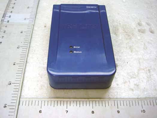
S9ZTEWMP1U
Mar 26, 2008Wireless Printer Server
Equipment Class
DTS - Digital Transmission System
S9ZTEW632BRP
Jan 06, 2008300Mbps Wireless N Home Router
Equipment Class
DTS - Digital Transmission System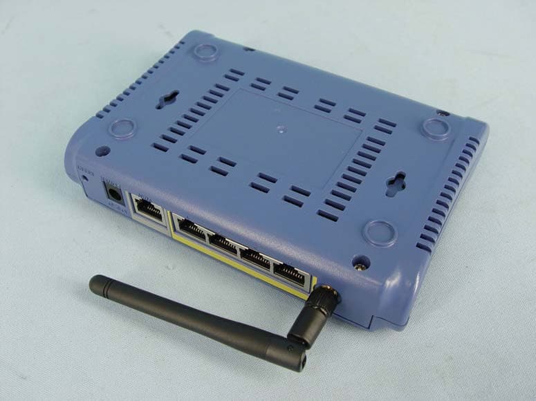
S9ZTEW432BRPD
Jan 02, 200854Mbps Wireless G Broadband Router
Equipment Class
DTS - Digital Transmission System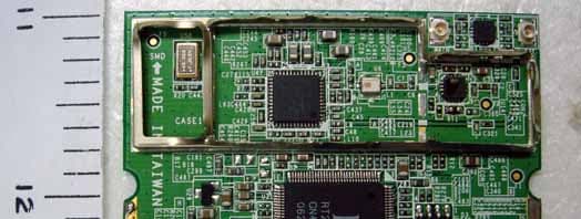
S9ZTEWMP2U
May 29, 2007Wireless MultiFunction Printer Server
Equipment Class
DTS - Digital Transmission System
S9ZTEW434APB
May 24, 200754Mbps Wireless Access Point with PoE
Equipment Class
DTS - Digital Transmission System