SBP23422Remotelinc 2 WIreless Controller
Insteon Technologies, LLC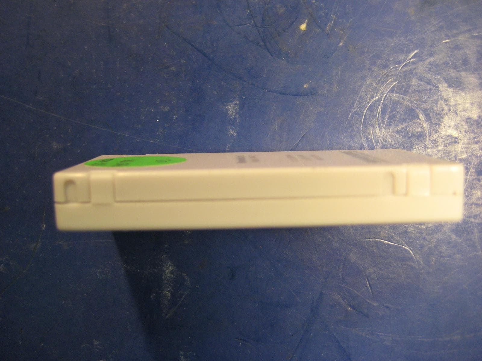
Click to zoom
Application Details
- Equipment Class
- DXT - Part 15 Low Power Transceiver, Rx Verified
- Date of Grant
- Mar 05, 2012
- Application Purpose
- Original Equipment
- Date of Application
- Mar 05, 2012
- Equipment Note
- Remotelinc 2 WIreless Controller
- Frequency Range
- 914.92000000 - 915.08000000
- Company
- Insteon Technologies, LLC
- Country
- United States
Documents & Files
Document Text
Text extracted from the exhibit documents filed with the FCC. Open a document above to read the original.
Users Manual
RemoteLinc 2 Rev. 2/16/2012 3:28 PM / See Owners Manual for Warranty Information, Patented © Copyright 2012, Smarthome, 16542 Millikan Ave., Irvine, CA 92606, 800-762-7845 Status LED Set button Micro-USB Charging Jack Power Switch (Left Off, Right On) Quick-Start Guide RemoteLinc ™ 2 - INSTEON ® Wireless Controller Model: 2342-2 Model: 2342-3 Introduction Use the power of INSTEON to control your home with the convenience of a compact and versatile wireless controller. What's Included RemoteLinc 2 Getting Started It is recommended that you fully charge your RemoteLinc 2 prior to programming. RemoteLinc 2 charges via a USB cable (Type A to Micro-B, sold separately). The red charging LED will turn off once the battery has been fully charged. To turn on RemoteLinc 2, simpl y slide the power switch to the on position. Using RemoteLinc 2 RemoteLinc 2 contains four on/off button pairs. Each pair controls its own scene, sending commands to devices linked specifically to the on/off button pair. Dimmable responders may behave differently, depending on whether you tap, double-tap, or press & hold a button to activate/deactivate a scene. Non-dimming responders will only turn full-on or full-off, no matter what method you use. Tap Double-tap Press & hold Ramp to on-Level or off Full-bright or full-off instantly Brighten or dim until released The RemoteLinc 2 Status LED will flash GREEN once for each ON/BRIGHT command sent and RED once for each OFF/DIM command sent Warning: RemoteLinc 2 is permanently sealed. Do not attempt to open case. Doing so will damage the remote. Add RemoteLinc 2 (Button) to a Scene as a Controller 1) Tap on "^" on the RemoteLinc 2 scene button of choice 2) Adjust the responder to the "state" you want when the scene is activated from RemoteLinc 2 1 3) Press & hold RemoteLinc 2's Set button until the RemoteLinc 2 beeps RemoteLinc 2’s LED will begin blinking GREEN 4) Press & hold the responder’s Set button until the responder beeps (or until LED/Load flashes) RemoteLinc 2 will double-beep and its LED will stop blinking Responder’s LED will stop blinking (it may also double-beep) 5) Confirm that scene addition was successful by tapping on/off on your chosen RemoteLinc 2 button The responder will toggle between the scene on level and off 1 If the responder is a multi-scene device, tap the Scene button you wish to control until it's LED is in the desired state (on or off) Scene Buttons (Left Off, Right On) Charging LED RemoteLinc 2 Rev. 2/16/2012 3:28 PM / See Owners Manual for Warranty Information, Patented © Copyright 2012, Smarthome, 16542 Millikan Ave., Irvine, CA 92606, 800-762-7845 FCC Compliance This device complies with FCC Rules Part 15. Operation is subject to two conditions: (1) This device may not cause harmful interference, and (2) This device must accept any interference that may be received or that may cause undesired operation. The digital circuitry of this device has been tested and found to comply with the limits for a Class B digital device, pursuant to Part 15 of the FCC Rules. These limits are designed to provide reasonable protection against harmful interference in residential installations. This equipment generates, uses and can radiate radio frequency energy and, if not installed and used in accordance with the instructions, may cause harmful interference to radio and television reception. However, there is no guarantee that interference will not occur in a particular installation. If this device does cause such interference, which can be verified by turning the device off and on, the user is encouraged to eliminate the interference by one or more of the following measures: • Re-orient or re-locate the receiving antenna of the device experiencing the interference. • Increase the distance between this device and the receiver. • Connect the device to an AC outlet on a circuit different from the one that supplies power to the receiver. • Consult the dealer or an experienced radio/TV technician. WARNING! Changes or modifications to this device not expressly approved by the party responsible for compliance could void the user's authority to operate the equipment. Industry Canada Compliance This device complies with Industry Canada license-exempt RSS standard(s). Operation is subject to the following two conditions: (1) this device may not cause interference, and (2) this device must accept any interference, including interference that may cause undesired operation of that device. Le prsent appareil est conforme aux CNR d'Industrie Canada applicables aux appareils radio exempts de licence. L'exploitation est autorise aux deux conditions suivantes: (1) l'appareil ne doit pas produire de brouillage, et (2) l'utilisateur de l'appareil doit accepter tout brouillage radiolectrique subi, mme si le brouillage est susceptible d'en compromettre le fonctionnement. Owner’s Manual & Tech Support Owner’s Manual: www.smarthome.com/manuals/2444A2xx4.pdf - Phone: 800-762-7845 For the most up-to-date Quick Start Guide visit http://www.smarthome.com/manuals/2444A2xx4qs.pdf
ID Label/Location Info
February 10, 2012 Subject: Unit Label RemoteLinc™ 2 - INSTEON® Wireless Controller #2342-2 RemoteLinc™ 2 - INSTEON® Wireless Controller #2342-3 FCC ID: SBP23422 IC: 5202A-23422 Specs: Width – 1.5 inches (38.0mm) Height – 1.2 inches (30.5mm) Pad Print on smooth case Unit Label
ID Label/Location Info
February 10, 2012 Subject: Unit Label Location RemoteLinc™ 2 - INSTEON ® Wireless Controller #2342-2 RemoteLinc™ 2 - INSTEON ® Wireless Controller #2342-3 FCC ID: SBP23422 IC: 5202A-23422 Unit Label Location
Test Report
This report contains a total of 32 pages and may be reproduced in full only. Partial reproduction may only be done with the written consent of CKC Laboratories, Inc. SmartLabs, Inc. TEST REPORT FOR RemoteLinc 2, 2342-2 Tested To The Following Standards: FCC Part 15 Subpart C Sections 15.249 and RSS-210 Issue 8 Report No.: 92540-10 Date of issue: January 31, 2012 This test report bears the accreditation symbol indicating that the testing performed herein meets the test and reporting requirements of ISO/IEC 17025 under the applicable scope of EMC testing for CKC Laboratories, Inc. We strive to create long-term, trust based relationships by providing sound, adaptive, customer first testing services. We embrace each of our customers’ unique EMC challenges, not as an interruption to set processes, but rather as the reason we are in business. Page 2 of 32 Report No.: 92540-10 TABLE OF CONTENTS Administrative Information .......................................................................................................................... 3 Test Report Information ............................................................................................................................................ 3 Report Authorization ................................................................................................................................................. 3 Test Facility Information ............................................................................................................................................ 4 Site Registration & Accreditation Information .......................................................................................................... 4 Summary of Results ................................................................................................................................................... 5 Conditions During Testing.......................................................................................................................................... 5 Equipment Under Test ............................................................................................................................................... 6 Peripheral Devices ..................................................................................................................................................... 6 FCC Part 15 Subpart C Section 15.249 .......................................................................................................... 7 FCC §15.31(e) Voltage Variations .............................................................................................................................. 7 FCC §15.249(a) RF Power Output ............................................................................................................................ 10 FCC §2.1049(I) -20dBc Occupied Bandwidth ........................................................................................................... 15 Bandedge ................................................................................................................................................................. 18 FCC §15.249(b)/(d) Field Strength of Spurious and Harmonic Emissions ................................................................ 22 RSS-210 ....................................................................................................................................................... 28 99% Bandwidth ........................................................................................................................................................ 28 Supplemental Information .......................................................................................................................... 31 Measurement Uncertainty ...................................................................................................................................... 31 Emissions Test Details .............................................................................................................................................. 31 Page 3 of 32 Report No.: 92540-10 ADMINISTRATIVE INFORMATION Test Report Information REPORT PREPARED FOR: REPORT PREPARED BY: SmartLabs, Inc. 16542 Millikan Ave. Irvine, CA 92606 Joyce Walker CKC Laboratories, Inc. 5046 Sierra Pines Drive Mariposa, CA 95338 REPRESENTATIVE: Matthew Meyer Project Number: 92540 Customer Reference Number: 12-3MM0106-01 DATE OF EQUIPMENT RECEIPT: January 11, 2012 DATE(S) OF TESTING: January 11 - 13, 2012 Report Authorization The test data contained in this report documents the observed testing parameters pertaining to and are relevant for only the sample equipment tested in the agreed upon operational mode(s) and configuration(s) as identified herein. Compliance assessment remains the client’s responsibility. This report may not be used to claim product endorsement by A2LA or any government agencies. This test report has been authorized for release under quality control from CKC Laboratories, Inc. Steve Behm Director of Quality Assurance & Engineering Services CKC Laboratories, Inc. Page 4 of 32 Report No.: 92540-10 Test Facility Information Our laboratories are configured to effectively test a wide variety of product types. CKC utilizes first class test equipment, anechoic chambers, data acquisition and information services to create accurate, repeatable and affordable test results. TEST LOCATION(S): CKC Laboratories, Inc. 110 Olinda Place Brea, CA 92823 Site Registration & Accreditation Information Location CB # JAPAN CANADA FCC Brea A US0060 R-2945, C-3248 & T-1572 3082D-1 90473 Page 5 of 32 Report No.: 92540-10 SUMMARY OF RESULTS Standard / Specification: FCC Part 15 Subpart C and RSS-210 Issue 8 Description Test Procedure/Method Results Voltage Variation FCC Part 15 Subpart C Section 15.31(e) Pass RF Power Output FCC Part 15 Subpart C Section 15.249(a) Pass -20dBc Occupied Bandwidth FCC Part 2.1049(I) Pa…
Text truncated - open the document above for the full version.
Test Setup Photos
X Axis Y Axis Z Axis
Contact Information
Applicant
John Lockyer(Suite 105-665)
Technical Contact
Smartlabs Inc.Matthew Meyer
[email protected]949-221-0037
16542 Millikan Avenue · Irvine, California · United States
Test Firm
CKC Laboratories, Inc.Steve Behm
Technical Specifications
| # | Rule Parts | Frequency Range | Power Output |
|---|---|---|---|
| 1 | 15C | 914.92 MHz - 915.08 MHz | - |
Other Applications from Insteon Technologies, LLC

SBP-MS01
Nov 28, 2020Multi Sensor
Equipment Class
DXX - Part 15 Low Power Communication Device Transmitter
SBP-BC01
Sep 10, 2020Bridge Controller
Equipment Class
DSS - Part 15 Spread Spectrum Transmitter
SBP-WR01
Mar 21, 2020Smart Outlet
Equipment Class
DXX - Part 15 Low Power Communication Device Transmitter
SBP-WALL
Mar 19, 2020Smart Wall Switch
Equipment Class
DXX - Part 15 Low Power Communication Device Transmitter
SBP26632
Sep 30, 2014On/Off Outlet
Equipment Class
DXT - Part 15 Low Power Transceiver, Rx Verified