SBP2440INSTEON RemoteLinc Wireless Remote Control #2440
Insteon Technologies, LLC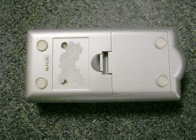
Click to zoom
Application Details
- Equipment Class
- DXT - Part 15 Low Power Transceiver, Rx Verified
- Date of Grant
- Jun 02, 2010
- Application Purpose
- Original Equipment
- Date of Application
- Jun 02, 2010
- Equipment Note
- INSTEON RemoteLinc Wireless Remote Control #2440
- Frequency Range
- 915.00000000 - 915.00000000
- Company
- Insteon Technologies, LLC
- Country
- United States
Documents & Files
Document Text
Text extracted from the exhibit documents filed with the FCC. Open a document above to read the original.
Users Manual
INSTEON RemoteLinc INSTEON-compatible Wireless Handheld Controller For models: #2440 RemoteLinc Handheld Controller ™ INSTEON-compatible RemoteLinc User’s Guide TABLE OF CONTENTS ABOUT REMOTELINC................................................................................................................................. 3 What is INSTEON?.................................................................................................................................... 3 Key RemoteLinc Features ......................................................................................................................... 3 HOW TO INSTALL REMOTELINC .............................................................................................................. 4 RemoteLinc Installation ............................................................................................................................. 4 HOW TO SET UP REMOTELINC ................................................................................................................ 5 Linking RemoteLinc to an INSTEON Device............................................................................................. 5 Unlinking One INSTEON Device from RemoteLinc .................................................................................. 6 Creating an INSTEON Scene.................................................................................................................... 6 ADVANCED FEATURES OF REMOTELINC .............................................................................................. 7 Resetting One ON/OFF Button to Its Factory Default Settings ................................................................. 7 Resetting RemoteLinc to Its Factory Default Settings............................................................................... 7 Turning the Audio Beeper On and Off....................................................................................................... 8 Turning the Status LED On and Off .......................................................................................................... 8 Stuck Button Feature................................................................................................................................. 8 SETUP SUMMARY....................................................................................................................................... 9 HOW TO USE REMOTELINC .................................................................................................................... 10 Using RemoteLinc’s Buttons ................................................................................................................... 10 Using the ON and OFF Buttons .............................................................................................................. 10 Using the ALL ON and ALL OFF Buttons................................................................................................ 11 Using the BRIGHT and DIM Buttons....................................................................................................... 12 ABOUT INSTEON ...................................................................................................................................... 13 Understanding Why an INSTEON Network Is Reliable........................................................................... 13 Further Enhancing Reliability .................................................................................................................. 13 Using SmartLab’s AccessPoint to Upgrade Your INSTEON Network .................................................... 13 TROUBLESHOOTING................................................................................................................................ 14 SPECIFICATIONS ...................................................................................................................................... 16 RemoteLinc Specifications ...................................................................................................................... 16 FCC Compliance Statement.................................................................................................................... 17 Limited Warranty ..................................................................................................................................... 18 INSTEON-compatible RemoteLinc User’s Guide Page 3 of 18 ABOUT REMOTELINC Congratulations on purchasing the INSTEON™ RemoteLinc™ Handheld Controller. RemoteLinc allows you to use the power of INSTEON to control your home with the convenience of a handheld wireless controller. What is INSTEON? INSTEON is a simple, reliable, and affordable breakthrough in home control. Simple, because Plug-n- Tap™ setup is a breeze, and there are no wires to add – INSTEON uses existing powerline wiring as well as radio-frequency for communication. And reliable, because every INSTEON device is a two-way repeater. An INSTEON home grows in value with every INSTEON device you add, making life more convenient, safe and fun. Key RemoteLinc Features • Six individual on/off buttons, plus dedicated DIM, BRIGHT, ALL ON and ALL OFF buttons. • Setup is easy – install four AAA batteries (included), link RemoteLinc buttons to devices with simple button taps, and you’re up and running. • Shows command transmission activity with status LED • Stores setup state in memory, even with batteries removed. • Smart circuitry detects abnormally long button presses (like those ocurring when remote falls between couch cushions) and puts RemoteLinc into sleep mode, preserving battery life. • Warranted for two years 6 ON/OFF Buttons Customizable Label Insert Status LED Simultaneously control all linked devices Dedicated DIM/BRIGHT buttons INSTEON-compatible RemoteLinc User’s Guide Page 4 of 18 HOW TO INSTALL REMOTELINC RemoteLinc Installation • Remove battery compartment door from r…
Text truncated - open the document above for the full version.
Cover Letter(s)
Scott McCutchan From: Scott McCutchan [[email protected]] Sent: Tuesday, July 17, 2007 11:02 AM To: 'Joey Madlangbayan' Subject: FCC ID: SBP2440 7/17/2007 Mr. Madlangbayan: In order for processing of this certification application (FCC ID: SBP2440) to continue, the following issue(s) will have to be addressed: 1) Please provide a signed TCB contract. 2) The letter of authority authorizes Compatible Electronics to make representations to the FCC, and not CETCB. Please submit a revised letter. 3) If confidentiality is requested, please submit a letter requesting confidentiality. 4) Please submit a letter stating that this application has not been submitted to another TCB. The item(s) indicated above must be submitted before processing can continue on the above referenced application. Failure to provide the requested information within 60 days of the original e-mail date may result in application dismissal and forfeiture of the filing fee. Also, please note that partial responses increase processing time and should not be submitted. Please upload responses and/or exhibits to the electronic filing website. Your correspondence number is SBP2440-1. Best regards, Scott McCutchan Operations Manager Compatible Electronics TCB
Test Report
Report Number: C70409H1 FCC Part 15 Subpart B and FCC Se ction 15.249 Test Report 19121 EL TORO ROAD, LAKE FOREST, CALIFORNIA, 92676 • PH: (949) 589-0700 FX: (949) 589-7700 Page 1 of 16 FCC PART 15 SUBPART B & C TEST REPORT for REMOTELINC Model: 2440 FCC ID: SBP2440 Prepared for SMARTLABS, INC. 16542 MILLIKAN AVENUE IRVINE, CALIFORNIA 92606 Prepared by:_____________________ JOEY MADLANGBAYAN Approved by:____________________ ELI McCLURE COMPATIBLE ELECTRONICS INC. 19121 EL TORO ROAD LAKE FOREST (SILVERADO), CALIFORNIA 92676 (949) 589-0700 DATE: JUNE 6, 2007 REPORT APPENDICES TO TAL BODY A B C D E PAGES 16 2 2 2 12 13 47 This report shall not be reproduced except in full, without the written approval of Compatible Electronics. Report Number: C70409H1 FCC Part 15 Subpart B and FCC Se ction 15.249 Test Report 19121 EL TORO ROAD, LAKE FOREST, CALIFORNIA, 92676 • PH: (949) 589-0700 FX: (949) 589-7700 Page 2 of 16 TABLE OF CONTENTS Section / Title PAGE GENERAL REPORT SUMMARY 4 1. PURPOSE 5 2. ADMINISTRATIVE DATA 6 2.1 Location of Testing 6 2.2 Traceability Statement 6 2.3 Cognizant Personnel 6 2.4 Date Test Sample was Received 6 2.5 Disposition of the Test Sample 6 2.6 Abbreviations and Acronyms 6 3. APPLICABLE DOCUMENTS 7 4. DESCRIPTION OF TEST CONFIGURATION 8 4.1 Description of Test Configuration - EMI 8 4.1.1 Photograph Test Configuration - EMI 8 4.1.2 Cable Construction and Termination 9 5 LISTS OF EUT, ACCESSORIES AND TEST EQUIPMENT 10 5.1 EUT and Accessory List 10 5.2 EMI Test Equipment 11 5.3 EMI Measurement and Control Software Information 12 6. TEST SITE DESCRIPTION 13 6.1 Test Facility Description 13 6.2 EUT Mounting, Bonding and Grounding 13 6.3 Facility Environmental Characteristics 13 7. TEST PROCEDURES 14 7.1 RF Emissions 14 7.1.1 Conducted Emissions Test 14 7.1.2 Radiated Emissions Test 15 8. TEST PROCEDURE DEVIATIONS 16 9. CONCLUSIONS 16 Report Number: C70409H1 FCC Part 15 Subpart B and FCC Se ction 15.249 Test Report 19121 EL TORO ROAD, LAKE FOREST, CALIFORNIA, 92676 • PH: (949) 589-0700 FX: (949) 589-7700 Page 3 of 16 LIST OF APPENDICES APPENDIX TITLE A Laboratory Accreditations and Recognitions B Modifications to the EUT C Additional Models Covered Under This Report D Diagrams, Charts, and Photos • Test Setup Diagrams • Antenna and Amplifier Gain Factors • Radiated and Conducted Emissions Photos E Data Sheets LIST OF FIGURES FIGURE TITLE 1 Conducted Emissions Test Setup 2 Plot Map And Layout of Test Site Report Number: C70409H1 FCC Part 15 Subpart B and FCC Se ction 15.249 Test Report 19121 EL TORO ROAD, LAKE FOREST, CALIFORNIA, 92676 • PH: (949) 589-0700 FX: (949) 589-7700 Page 4 of 16 GENERAL REPORT SUMMARY This electromagnetic emission test report is generated by Compatible Electronics Inc., which is an independent testing and consulting firm. The test report is based on testing performed by Compatible Electronics personnel according to the measurement procedures described in the test specifications given below and in the "Test Procedures" section of this report. The measurement data and conclusions appearing herein relate only to the sample tested and this report may not be reproduced in any form unless done so in full with the written permission of Compatible Electronics. This report must not be used to claim product endorsement by NVLAP, NIST, or any other agency of the U.S. Government or other governments. Device Tested: RemoteLinc Model: 2440 S/N: None Product Description: This is a 916MHz range remote control transmitter used for the purpose of controlling an AC outlet. Modifications: The EUT was not modified during the testing. Manufacturer: SmartLabs, Inc. 16542 Millikan Avenue Irvine, California 92606 Test Dates: February 28 & April 6, 2007 Test Specifications: EMI requirements CFR Title 47, FCC Part 15 Subpart B and Subpart C Sections 15.205, 15.209 and 15.249 Test Procedure: ANSI C63.4: 2003 SUMMARY OF TEST RESULTS TEST DESCRIPTION RESULTS 1 Conducted RF Emissions, 150 kHz - 30 MHz. The EUT does not connect to AC mains, therefore this test was not performed. 2 Radiated RF Emissions, 9 kHz - 9150 MHz. Complies with the limits of CFR Title 47 Part 15 Subpart B (Class B devices) and Subpart C sections 15.205, 15.209 and 15.249. Report Number: C70409H1 FCC Part 15 Subpart B and FCC Se ction 15.249 Test Report 19121 EL TORO ROAD, LAKE FOREST, CALIFORNIA, 92676 • PH: (949) 589-0700 FX: (949) 589-7700 Page 5 of 16 1. PURPOSE This document is a qualification test report based on the Electromagnetic Interference (EMI) tests performed on RemoteLinc Model: 2440. The EMI measurements were performed according to the measurement procedure described in ANSI C63.4: 2003. The tests were performed in order to determine whether the electromagnetic emissions from the equipment under test, referred to as EUT hereafter, are within the Class B specification limits defined by Code of Federal Regulations Title 47, Part 15 Subpart B and Subpart C sections 15.205, 15.209 and 15.249. Report Number: C70409H1 FCC Part 15 Subpart B and FCC Se ction 15.249 Test Report 19121 EL TORO ROAD, LAKE FOREST, CALIFORNIA, 92676 • PH: (949) 589-0700 FX: (949) 589-7700 Page 6 of 16 2. ADMINISTRATIVE DATA 2.1 Location of Testing The EMI tests described herein were performed at the test facility of Compatible Electronics, 19121 El Toro Road, Lake Forest (Silverado), California 92676. 2.2 Traceability Statement The calibration certificates of all test equipment used during the test are on file at the location of the test. The calibration is traceable to the National Institute of Standards and Technology (NIST). 2.3 Cognizant Personnel SmartLabs, Inc. Mike Pearson VP of Engineering Compatible Electronics, Inc. Joey Madlangbayan Test Engineer Eli McClure Test Technician 2.4 Date Test Sample was Received The test sample was received on February 28, 2007. 2.5 Disposition of the Test Sample The test sample remains at Compatible Electronics, Inc. as of June 6, 2007. 2.6 Abbreviations and Acronyms The following abb…
Text truncated - open the document above for the full version.
Contact Information
Applicant
John Lockyer(Suite 105-665)
Technical Contact
Compatible Electronics, Inc.Joey Madlangbayan
[email protected]949-589-0700
19121 El Toro Road · Silverado, California · United States
Test Firm
Compatible Electronics, Inc.Michael Christensen
Technical Specifications
| # | Rule Parts | Frequency Range | Power Output |
|---|---|---|---|
| 1 | 15C | 915 MHz - 915 MHz | - |
Other Applications from Insteon Technologies, LLC

SBP-MS01
Nov 28, 2020Multi Sensor
Equipment Class
DXX - Part 15 Low Power Communication Device Transmitter
SBP-BC01
Sep 10, 2020Bridge Controller
Equipment Class
DSS - Part 15 Spread Spectrum Transmitter
SBP-WR01
Mar 21, 2020Smart Outlet
Equipment Class
DXX - Part 15 Low Power Communication Device Transmitter
SBP-WALL
Mar 19, 2020Smart Wall Switch
Equipment Class
DXX - Part 15 Low Power Communication Device Transmitter
SBP26632
Sep 30, 2014On/Off Outlet
Equipment Class
DXT - Part 15 Low Power Transceiver, Rx Verified