SBP2440AHandheld Wireless Remote Control (Model: 2440)
Insteon Technologies, LLC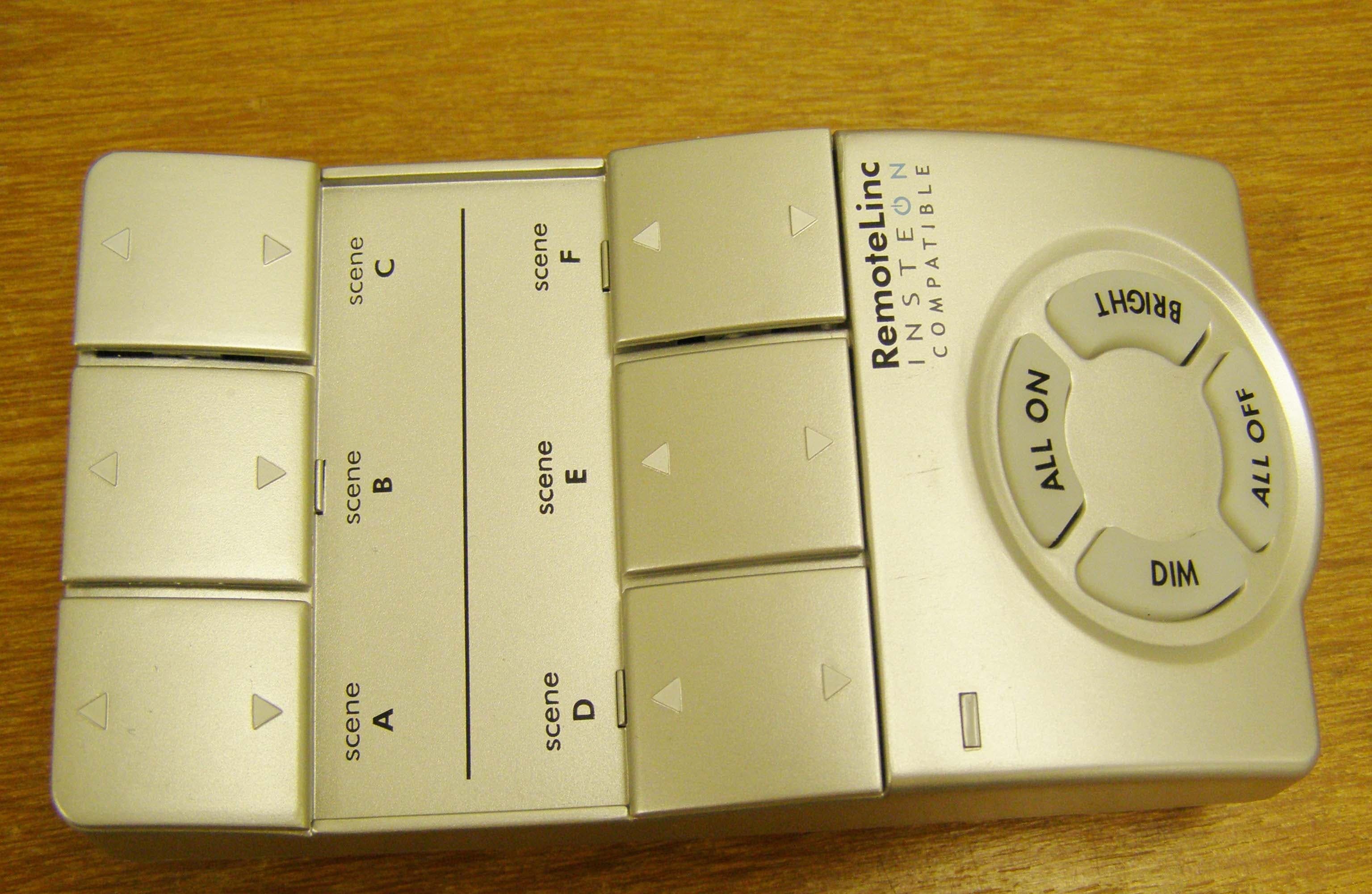
Click to zoom
Application Details
- Equipment Class
- DXT - Part 15 Low Power Transceiver, Rx Verified
- Date of Grant
- Jun 30, 2011
- Application Purpose
- Original Equipment
- Date of Application
- Jun 30, 2011
- Equipment Note
- Handheld Wireless Remote Control (Model: 2440)
- Frequency Range
- 915.00000000 - 915.00000000
- Company
- Insteon Technologies, LLC
- Country
- United States
Documents & Files
Document Text
Text extracted from the exhibit documents filed with the FCC. Open a document above to read the original.
Users Manual
June 21, 2011 Handheld Wireless Remote Control Model: 2440 FCC ID: SBP2440A IC: 5202A-2440A The owner’s manual below may be accessed freely via the Internet with any web browser and supports the PDF format. http://www.smarthome.com/2440/RemoteLinc-INSTEON-Wireless- Remote-Control-Silver/p.aspx Complies with Section 5 of FCC document 784748 D01 Labeling Part 15 18 Guidelines v07 where cautionary statements in the user manual may be provided over the Internet. On-Line Owner’s Manual Containing Cautionary FCC & IC Statements RemoteLinc ™ INSTEON ® Wireless Remote Control Model : 2440 RemoteLinc Owner’s Manual TABLE OF CONTENTS ABOUT REMOTELINC................................................................................................................................. 3 Key RemoteLinc Features......................................................................................................................... 3 What is Included with RemoteLinc............................................................................................................ 3 WHAT IS INSTEON?.................................................................................................................................... 4 INSTALLATION............................................................................................................................................ 4 Installing RemoteLinc................................................................................................................................4 USING REMOTELINC.................................................................................................................................. 5 Using the RemoteLinc Buttons.................................................................................................................. 5 Creating a Custom RemoteLinc Label...................................................................................................... 5 CONTROLLING INSTEON RESPONDERS FROM SWITCHLINC DIMMER............................................. 6 Linking RemoteLinc to an INSTEON Responder...................................................................................... 6 Unlinking an INSTEON Responder from RemoteLinc.............................................................................. 6 CREATING AN INSTEON SCENE............................................................................................................... 7 ADVANCED FEATURES............................................................................................................................. 7 Multi-Linking and Multi-Unlinking............................................................................................................... 7 Enabling / Disabling the Beeper................................................................................................................ 8 Enabling / Disabling the Status LED......................................................................................................... 8 Stuck Button Feature................................................................................................................................. 9 Restoring Power to RemoteLinc................................................................................................................ 9 Resetting RemoteLinc to its Factory Default Settings............................................................................... 9 ABOUT INSTEON...................................................................................................................................... 10 Using Dual-Band INSTEON Devices to Upgrade Your Network............................................................. 10 Important Note about INSTEON Networks; Split Single-Phase vs. 3-Phase Installation....................... 10 Further Enhancing Reliability.................................................................................................................. 10 ADDITIONAL RESOURCES...................................................................................................................... 10 TROUBLESHOOTING................................................................................................................................11 SPECIFICATIONS, CERTIFICATION, AND WARRANTY........................................................................ 12 Specifications.......................................................................................................................................... 12 FCC & Industry Canada Compliance Statement..................................................................................... 12 Limited Warranty..................................................................................................................................... 13 RemoteLinc Owner’s Manual Page 3 of 13 ABOUT REMOTELINC Congratulations on purchasing the INSTEON RemoteLinc. With its sleek, handheld design, RemoteLinc allows you to use the power of INSTEON to control your home with the convenience of a wireless radio frequency (RF) controller. On/Off button pairs Customizable label insert Status LED Dedicated simultaneous- control buttons Dedicated Dim/Bright buttons Key RemoteLinc Features • Setup is easy – install four AAA batteries (included), and then Link to other devices in minutes • Six individual On/Off button pairs, plus dedicated Dim, Bright, All On and All Off buttons • Shows command transmission activity with a Status LED and beeper (both features easily disabled/re-enabled) • Stores setup state in memory so settings aren’t lost when batteries are removed • Smart circuitry detects abnormally long button presses (like those occurring when the remote falls between couch cushions) and puts RemoteLinc into sleep mode to preserve battery life • Two-year warranty What is Included with RemoteLinc • RemoteLinc – INSTEON Wireless Remote Control • Four (4) AAA batteries • Quick-Start Guide RemoteLinc…
Text truncated - open the document above for the full version.
ID Label/Location Info
June 21, 2011 Subject: Unit Label Handheld Wireless Remote Control Model: 2440 FCC ID: SBP2440A IC: 5202A-2440A Specs: Width – 1.65 inches (41.9mm) Height – 1.137 inches (28.9mm) Surface Material: gloss white polyester face stock with a smooth, absorbent ink-receptive top coating Surface Material Thickness - .050 mm ± 10% ISO534 Base Material – Super-Calendared White Glassine Paper Base Thickness - 0.070mm ± 10% ISO534 Adhesive Base – Acrylic .025mm Thickness 24 hour 90° Peel (st,st)-FTM 2: 7.5 Service Temperature Range: -40°C~+80°C (when applied to polycarbonate) UL Recognized Listing # MH47798 Unit Label
ID Label/Location Info
June 21, 2011 Handheld Wireless Remote Control Model: 2440 FCC ID: SBP2440A IC: 5202A-2440A Unit Label Location
Test Report
Report Number: D10623R1 FCC Part 15 Subpart B and FCC Section 15.249 Test Report Handheld Wireless Remote Control FCC ID: SBP2440A Brea Division 114 Olinda Drive Brea, CA 92823 (714) 579-0500 Agoura Division 2337 Troutdale Drive Agoura, CA 91301 (818) 597-0600 Silverado Division 19121 El Toro Road Silverado, CA 92676 (949) 589-0700 Lake Forest Division 20621 Pascal Way Lake Forest, CA 92630 (949) 587-0400 Page 1 of 18 FCC PART 15 SUBPART B & C TEST REPORT for HANDHELD WIRELESS REMOTE CONTROL Model: 2440 Prepared for SmartLabs, Inc. 16542 MILLIKAN AVENUE IRVINE, CA 92606 USA Prepared by:_____________________ JOEY MADLANGBAYAN Approved by:____________________ JOSH HANSEN COMPATIBLE ELECTRONICS INC. 20621 PASCAL WAY LAKE FOREST, CALIFORNIA 92630 (949) 589-0700 DATE: JUNE 27, 2011 REPORT APPENDICES TOTAL BODY A B C D E PAGES 18 2 2 2 10 12 46 This report shall not be reproduced except in full, without the written approval of Compatible Electronics. Report Number: D10623R1 FCC Part 15 Subpart B and FCC Section 15.249 Test Report Handheld Wireless Remote Control FCC ID: SBP2440A Brea Division 114 Olinda Drive Brea, CA 92823 (714) 579-0500 Agoura Division 2337 Troutdale Drive Agoura, CA 91301 (818) 597-0600 Silverado Division 19121 El Toro Road Silverado, CA 92676 (949) 589-0700 Lake Forest Division 20621 Pascal Way Lake Forest, CA 92630 (949) 587-0400 Page 2 of 18 TABLE OF CONTENTS Section / Title PAGE GENERAL REPORT SUMMARY 4 SUMMARY OF TEST RESULTS 5 1. PURPOSE 6 2. ADMINISTRATIVE DATA 7 2.1 Location of Testing 7 2.2 Traceability Statement 7 2.3 Cognizant Personnel 7 2.4 Date Test Sample was Received 7 2.5 Disposition of the Test Sample 7 2.6 Abbreviations and Acronyms 7 3. APPLICABLE DOCUMENTS 8 4. DESCRIPTION OF TEST CONFIGURATION 9 4.1 Description of Test Configuration - EMI 9 4.1.1 Photograph Test Configuration - EMI 9 4.1.2 Cable Construction and Termination 10 5. LISTS OF EUT, ACCESSORIES AND TEST EQUIPMENT 11 5.1 EUT and Accessory List 11 5.2 EMI Test Equipment 12 6. TEST SITE DESCRIPTION 13 6.1 Test Facility Description 13 6.2 EUT Mounting, Bonding and Grounding 13 6.3 Facility Environmental Characteristics 13 7. CHARACTERISTICS OF THE TRANSMITTER 14 7.1 Channel Number and Frequencies 14 7.2 Antenna 14 7.3 Modulation 14 8. TEST PROCEDURES 15 8.1 RF Emissions 15 8.1.1 Conducted Emissions Test 15 8.1.2 Radiated Emissions (Spurious and Harmonics) Test 16 8.1.3 Peak Transmit EMI 16 8.1.4 Band Edge 17 9. TEST PROCEDURE DEVIATIONS 18 10. CONCLUSIONS 18 Report Number: D10623R1 FCC Part 15 Subpart B and FCC Section 15.249 Test Report Handheld Wireless Remote Control FCC ID: SBP2440A Brea Division 114 Olinda Drive Brea, CA 92823 (714) 579-0500 Agoura Division 2337 Troutdale Drive Agoura, CA 91301 (818) 597-0600 Silverado Division 19121 El Toro Road Silverado, CA 92676 (949) 589-0700 Lake Forest Division 20621 Pascal Way Lake Forest, CA 92630 (949) 587-0400 Page 3 of 18 LIST OF APPENDICES APPENDIX TITLE A Laboratory Accreditations and Recognitions B Modifications to the EUT C Additional Models Covered Under This Report D Diagrams, Charts, and Photos Test Setup Diagrams Antenna Factors Radiated and Conducted Emissions Photos E Data Sheets LIST OF FIGURES FIGURE TITLE 1 Plot Map And Layout of Test Site 2 Radiated Emissions 3-Meter Semi-Anechoic Test Chamber Above 1 GHz Report Number: D10623R1 FCC Part 15 Subpart B and FCC Section 15.249 Test Report Handheld Wireless Remote Control FCC ID: SBP2440A Brea Division 114 Olinda Drive Brea, CA 92823 (714) 579-0500 Agoura Division 2337 Troutdale Drive Agoura, CA 91301 (818) 597-0600 Silverado Division 19121 El Toro Road Silverado, CA 92676 (949) 589-0700 Lake Forest Division 20621 Pascal Way Lake Forest, CA 92630 (949) 587-0400 Page 4 of 18 GENERAL REPORT SUMMARY This electromagnetic emission test report is generated by Compatible Electronics Inc., which is an independent testing and consulting firm. The test report is based on testing performed by Compatible Electronics personnel according to the measurement procedures described in the test specifications given below and in the "Test Procedures" section of this report. The measurement data and conclusions appearing herein relate only to the sample tested and this report may not be reproduced in any form unless done so in full with the written permission of Compatible Electronics. This report must not be used to claim product endorsement by NVLAP, NIST, or any other agency of the U.S. Government or other governments. Device Tested: Handheld Wireless Remote Control Model: 2440 S/N: 14.3D.6B Product Description: The EUT is a Wireless Remote Control transceiver. Modifications: The EUT was not modified in during the testing. Manufacturer: SmartLabs, Inc. 16542 Millikan Avenue Irvine, California 92606 Test Date: June 23, 2011 Test Specifications: EMI requirements CFR Title 47, Part 15 Subpart B and Subpart C Sections 15.205, 15.209 and 15.249 Test Procedure: ANSI C63.10 CFR 47, Part 15.31 Report Number: D10623R1 FCC Part 15 Subpart B and FCC Section 15.249 Test Report Handheld Wireless Remote Control FCC ID: SBP2440A Brea Division 114 Olinda Drive Brea, CA 92823 (714) 579-0500 Agoura Division 2337 Troutdale Drive Agoura, CA 91301 (818) 597-0600 Silverado Division 19121 El Toro Road Silverado, CA 92676 (949) 589-0700 Lake Forest Division 20621 Pascal Way Lake Forest, CA 92630 (949) 587-0400 Page 5 of 18 SUMMARY OF TEST RESULTS TEST DESCRIPTION RESULTS 1 Conducted RF Emissions, 150 kHz - 30 MHz. The EUT is a battery powered device and does not connect to the AC mains; therefore this test was not performed. 2 Spurious Radiated RF Emissions, 9 kHz – 30 MHz, 30 - 1,000 MHz, and 1,000 MHz – 10,000 MHz Complies with the Class B limits of CFR Title 47, Part 15, Subpart B; and CFR Title 47, Part 15, Subpart C, section 15.249(a) 3 Emissions produced by the intentional radiator , 9 kHz – 10 GHz Complies with the relevant requirements of CFR Title 47, Part 15, Subpart C, section 15.205, 15.209, 15.249 (d) 4 Peak T…
Text truncated - open the document above for the full version.
Contact Information
Applicant
John Lockyer(Suite 105-665)
Technical Contact
Compatible Electronics, Inc.Josh Hansen
[email protected]949-587-0400
20621 Pascal Way · Lake Forest · United States
Test Firm
Compatible Electronics, Inc.Jeff Klinger
Technical Specifications
| # | Rule Parts | Frequency Range | Power Output |
|---|---|---|---|
| 1 | 15C | 915 MHz - 915 MHz | - |
Other Applications from Insteon Technologies, LLC

SBP-MS01
Nov 28, 2020Multi Sensor
Equipment Class
DXX - Part 15 Low Power Communication Device Transmitter
SBP-BC01
Sep 10, 2020Bridge Controller
Equipment Class
DSS - Part 15 Spread Spectrum Transmitter
SBP-WR01
Mar 21, 2020Smart Outlet
Equipment Class
DXX - Part 15 Low Power Communication Device Transmitter
SBP-WALL
Mar 19, 2020Smart Wall Switch
Equipment Class
DXX - Part 15 Low Power Communication Device Transmitter
SBP26632
Sep 30, 2014On/Off Outlet
Equipment Class
DXT - Part 15 Low Power Transceiver, Rx Verified