SBP2441VRF Thermostat adapter for home automation
Insteon Technologies, LLC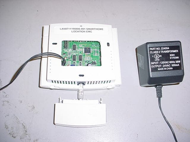
Click to zoom
Application Details
- Equipment Class
- DXT - Part 15 Low Power Transceiver, Rx Verified
- Date of Grant
- Feb 06, 2008
- Application Purpose
- Original Equipment
- Date of Application
- Feb 06, 2008
- Equipment Note
- RF Thermostat adapter for home automation
- Frequency Range
- 915.00000000 - 915.00000000
- Company
- Insteon Technologies, LLC
- Country
- United States
Documents & Files
Document Text
Text extracted from the exhibit documents filed with the FCC. Open a document above to read the original.
Users Manual
Page 1 of 2 Rev. 012208 Quick-Start Guide INSTEON™ Thermostat Adapter, Totaline™ / Venstar™ M Model: #2441V INSTEON Thermostat Adapter Introduction The INSTEON Thermostat Adapter adds remote control and monitoring to 3 models of Totaline / Venstar brand thermostats. It simply plugs into the bottom of compatible thermostats and communicates via INSTEON RF giving you wireless remote control and monitoring from anywhere in your home, or the world. The 3 compatible models are: 1-Day Programmable Venstar Thermostat (30410A) 7-Day Programmable Venstar Thermostat (30411A) 7-Day Programmable Dual-Fuel Venstar Thermostat (30412A) Installation 1) Simply plug the INSTEON Thermostat Adapter into the jack on the bottom of your thermostat The green LED will turn on Un-Install 1) Open the front “cover” of the thermostat by gently pulling the right edge of the cover towards you 2) While pressing firmly on the small round button (center, bottom of thermostat) pull down gently on the INSTEON Thermostat Adapter The INSTEON Thermostat Adapter will disconnect from the thermostat Adding your Thermostat Adapter to a Scene on your INSTEON Compatible Controller For example, let’s say you would like to remotely control your thermostat to 73 degrees, heat mode from the comfort and convenience of your couch, using the Scene A button on your RemoteLinc™ (If you want to use another INSTEON Compatible Controller, see its user manual) 1) Tap the mode button on your thermostat until the mode indicated is heat 2) Tap the up and/or down arrows on your thermostat until the temperature set point is 73 degrees 3) Press & hold the top of the Scene A button on your RemoteLinc (for about 10 seconds) until it beeps The LED will start blinking (Press & hold for 10 seconds works for just about every INSTEON compatible Controller. Please check your Controller’s owner’s manual if you need help) 4) Press & hold the button on the INSTEON Thermostat Adapter (for about 5 seconds) The LCD display on your thermostat will briefly display all its characters, then return to normal The INSTEON Adapter’s LED will blink off faintly, then return to steady on The RemoteLinc will beep and its LED will stop blinking 5) Tap the mode button on your thermostat (this will temporarily change the operating mode to allow you to test your remote control) Your thermostat’s mode will change to cool 6) Tap the Scene A (up arrow) on your RemoteLinc Your thermostat should return to heat mode with a 73-degree set point Button LED Page 2 of 2 Rev. 012208 Quick-Start Guide INSTEON Thermostat Adapter For HELP , call our friendly tech support @ 866-243-8018 SmartLabs Limited Warranty – SmartLabs warrants to the original consumer of this product that, for a period of two years from the date of purchase, this product will be free from defects in material and workmanship and will perform in substantial conformity to the description of the product in the owner's manual and/or quick start guide. This warranty shall not apply to defects or errors caused by misuse or neglect. © Copyright 2007 SmartLabs, 16542 Millikan Ave., Irvine, CA 92606-5027 – 866-243-8018 www.smartlabsinc.com Removing from a Scene 1) Put your Controller into “Delete from Scene” mode (usually “Unlinking” mode (two 10-second press & holds) – please check its Owner’s Manual if you need help) 2) Press & hold the INSTEON Thermostat Adapter’s button for about 5 seconds The LCD display on your thermostat will briefly display all its characters, then return to normal The INSTEON Adapter’s LED will blink off faintly, then return to steady on Factory Reset 1) Unplug the INSTEON Thermostat Adapter from your thermostat (see Un-Install section on page 1 for details) 2) Press & hold the button on the INSTEON Thermostat Adapter 3) While continuing to hold the button, plug the INSTEON Thermostat Adapter back into your thermostat 4) Continue to hold the button for approximately 5 seconds All user settings will be erased and the unit restored to its factory settings Advanced Operations Using software you will be able to integrate your automation of your thermostat with the wide array of INSTEON compatible products to save energy and time. For example, applications can include having an email sent to you if the temperature goes above or below any chosen set points, have a “goodbye” scene automatically set back your thermostat, etc. – the applications are almost endless. Check with your favorite INSTEON Compatible Software for their latest support for this product. Specifications FCC Compliance Statement INSTEON communications RF INSTEON Controller functionality Not supported INSTEON Responder functionality Supported INSTEON message repeating Supported, always on Mode control Heat, Cool, Auto, OFF Fan control On, Auto Degree format Fahrenheit (Celsius is not available) Maximum number of INSTEON scenes / links 417 All Linking Supported (10 sec set button push n hold) Unlink Supported (10 seconds press n hold, twice) Heat set point Supports all set points of Thermostat Cool set point Supports all set points of Thermostat Temperature status request Supported Humidity status request Supported Mode status request Supported Fan status request Supported X10 Not supported Dimensions 2.89” W x 1.75” H x 0.58” D LED Green Interconnect type Male, RJ10 4 conductor (aka RJ22) Input power 5VDC, 30 ma max (supplied by thermostat) Installation Indoor use only Approvals FCC, Industry Canada Warranty 2 years This device complies with FCC Rules Part 15. Operation is subject to two conditions: (1) This device may not cause harmful interference, and (2) this device must accept any interference that may be received or that may cause undesired operation. The digital circuitry of this device has been tested and found to comply with the limits for a Class B digital device, pursuant to Part 15 of the FCC Rules. These limits are designed to provide reasonable protection against harmful interference in residential installations. This equipment gene…
Text truncated - open the document above for the full version.
External Photos
27611 La Paz Road Suite C Laguna Niguel, CA 92677 Tel 949-448-4100 Fax 949-448-4111 SmartHome, Inc. Model: 2441V FCC ID: SBP2441V FCC Part 15.249 EXTERNAL PHOTOGRAPHS General view 27611 La Paz Road Suite C Laguna Niguel, CA 92677 Tel 949-448-4100 Fax 949-448-4111 SmartHome, Inc. Model: 2441V FCC ID: SBP2441V FCC Part 15.249 Rear View 27611 La Paz Road Suite C Laguna Niguel, CA 92677 Tel 949-448-4100 Fax 949-448-4111 SmartHome, Inc. Model: 2441V FCC ID: SBP2441V FCC Part 15.249 Front View
Internal Photos
27611 La Paz Road Suite C Laguna Niguel, CA 92677 Tel 949-448-4100 Fax 949-448-4111 SmartHome, Inc. Model: 2441V FCC ID: SBP2441V FCC Part 15.249 INTERNAL PHOTOGRAPHS General View 27611 La Paz Road Suite C Laguna Niguel, CA 92677 Tel 949-448-4100 Fax 949-448-4111 SmartHome, Inc. Model: 2441V FCC ID: SBP2441V FCC Part 15.249 PCB - Component View 27611 La Paz Road Suite C Laguna Niguel, CA 92677 Tel 949-448-4100 Fax 949-448-4111 SmartHome, Inc. Model: 2441V FCC ID: SBP2441V FCC Part 15.249 PCB – Solder View
Operational Description
A Brief, non-technical description of the unit and its operation. The INSTEON Thermostat Adapter product is a device that receives, transmits, and repeats RF signals between a controller device and itself. It connects to an external communications connector found on some Venstar Thermostat models. When a 915MHz FSK over-the air RF signal is detected by the INSTEON Thermostat Adapter module’s processor, the RF data is immediately repeated by the same transceiver circuit and then analyzed to determine if the message was for it. If the message was for it, the processor performs the required actions like turning on the connected thermostat and setting the desired temperature. The module may also initiate an RF transmission on the same band to a linked or slave receiver. For example, if the product determines that settings or the detected temperature has changed, it may communicate this information to a previously linked or learned receiver.
Test Report
27611 La Paz Rd., Suite C, Laguna Niguel, CA 92677 Date of Test: November 16 to 20, 2007 IC ID: 5202A-2441 FCC ID: SBP2441V Test Report for SmartHome, Inc. on the 2441V TEST REPORT Report Number: 3139455LAX-002 Project Number: 3139455 November 27, 2007 Testing performed on the Insteon Thermostat RF Adapter Model: 2441V to FCC Part 15.249 RSS-210 Part A2.9 For SmartHome, Inc. A2LA Certificate Number: 2085.01 Test Performed by: Test Authorized by: Intertek 27611 La Paz Rd., Suite C Laguna Niguel, CA 92677 SmartHome, Inc. 16542 Millikan Ave. Irvine, CA 92606 Prepared by: Date:11/27/07 Sergey Marker Reviewed by: Date:11/27/07 Ollie Moyrong This report is for the exclusive use of Intertek's Client and is provided pursuant to the agreement between Intertek and its Client. Intertek's responsibility and liability are limited to the terms and conditions of the agreement. Intertek assumes no liability to any party, other than to the Client in accordance with the agreement, for any loss, expense or damage occasioned by the use of this report. Only the Client is authorized to copy or distribute this report and then only in its entirety. Any use of the Intertek name or one of its marks for the sale or advertisement of the tested material, product or service must first be approved in writing by Intertek. The observations and test results in this report are relevant only to the sample tested. This report by itself does not imply that the material, product, or service is or has ever been under an Intertek certification program. File: 3139455LAX-002 Page 1 of 29 27611 La Paz Rd., Suite C, Laguna Niguel, CA 92677 Date of Test: November 16 to 20, 2007 IC ID: 5202A-2441 FCC ID: SBP2441V Test Report for SmartHome, Inc. on the 2441V File: 3139455LAX-002 Page 2 of 29 Table of Contents 1.0 Summary of Test Results............................................................................................................... 4 2.0 General Description ....................................................................................................................... 5 2.1 Product Description ............................................................................................................5 2.2 Related Submittal(s) Grants ................................................................................................ 6 2.3 Test Methodology ...............................................................................................................6 2.4 Test Facility ........................................................................................................................ 6 3.0 System Test Configuration............................................................................................................ 7 3.1 Justification ......................................................................................................................... 7 3.2 EUT Exercising Software ................................................................................................... 7 3.3 System Test Configuration ................................................................................................. 7 3.3.1 Support Equipment ................................................................................................ 7 3.3.2 Block Diagram of Test Setup................................................................................. 8 3.4 Equipment Modification ..................................................................................................... 8 3.5 Mode(s) of operation .......................................................................................................... 8 4.0 Field Strength of Emission ............................................................................................................ 9 4.1 Field Strength of Fundamental and Harmonics. ................................................................. 9 4.1.1 Test Procedure ....................................................................................................... 9 4.1.2 Field Strength Calculation ..................................................................................... 9 4.1.3 Radiated Emission Data....................................................................................... 11 4.2 Radiated Emission from Digital Parts and Receiver......................................................... 13 4.2.1 Test Procedure ..................................................................................................... 13 4.2.2 Field Strength Calculation ................................................................................... 13 4.2.3 Radiated Emission Data....................................................................................... 14 5.0 Out of Band Emission .................................................................................................................. 16 5.1 Test Description .................................................................................................................... 16 5.2 Test Procedure ..................................................................................................................... 16 5.3 Test Results .......................................................................................................................... 16 6.0 Antenna Requirement ................................................................................................................. 21 6.1 Test description .................................................................................................................... 21 6.2 Test Procedure ..................................................................................................................... 21 6.3 Test Result ........................................................................................................................... 21 7.0 Line Conducted Emission.....................................................................…
Text truncated - open the document above for the full version.
Test Setup Photos
SmartHome, Inc. Model: 2441V FCC ID: SBP2441V FCC Part 15.249 TEST SETUP PHOTOGRAPHS Radiated Emission measurements outside the band (15.249c). SmartHome, Inc. Model: 2441V FCC ID: SBP2441V FCC Part 15.249 Field Strength emission measurements (15.109, 15.249a) SmartHome, Inc. Model: 2441V FCC ID: SBP2441V FCC Part 15.249 . Line Conducted Emission (15.107, 15.207)
Contact Information
Applicant
John Lockyer(Suite 105-665)
Technical Contact
Intertek Testing Services NA, IncSergey Marker
[email protected](949) 448-4100
27611 La Paz Rd. · Laguna Niguel, California · United States
Non-Technical Contact
Smarthome, Inc.Dan Cregg
[email protected]949-221-9200
Test Firm
Intertek Testing Services NA, Inc.Charles Parker
Technical Specifications
| # | Rule Parts | Frequency Range | Power Output |
|---|---|---|---|
| 1 | 15C | 915 MHz - 915 MHz | - |
Other Applications from Insteon Technologies, LLC

SBP-MS01
Nov 28, 2020Multi Sensor
Equipment Class
DXX - Part 15 Low Power Communication Device Transmitter
SBP-BC01
Sep 10, 2020Bridge Controller
Equipment Class
DSS - Part 15 Spread Spectrum Transmitter
SBP-WR01
Mar 21, 2020Smart Outlet
Equipment Class
DXX - Part 15 Low Power Communication Device Transmitter
SBP-WALL
Mar 19, 2020Smart Wall Switch
Equipment Class
DXX - Part 15 Low Power Communication Device Transmitter
SBP26632
Sep 30, 2014On/Off Outlet
Equipment Class
DXT - Part 15 Low Power Transceiver, Rx Verified