SBP2442RF phase bridge for home automation
Insteon Technologies, LLC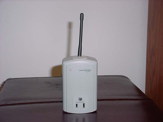
Click to zoom
Application Details
- Equipment Class
- DXX - Part 15 Low Power Communication Device Transmitter
- Date of Grant
- Aug 08, 2004
- Application Purpose
- Original Equipment
- Date of Application
- Aug 08, 2004
- Equipment Note
- RF phase bridge for home automation
- Frequency Range
- 904.00000000 - 904.00000000
- Company
- Insteon Technologies, LLC
- Country
- United States
Documents & Files
Document Text
Text extracted from the exhibit documents filed with the FCC. Open a document above to read the original.
Users Manual
AccessLinc TM Bridges Insteon Signals Between Wireless and Powerline For models: 2442 AccessLinc RF Bridge 2442 July 15,04_web.qxd 7/15/2004 10:59 AM Page 1 Congratulations! Thanks for purchasing and installing the AccessLinc™ for Insteon TM products. This simple, plug-in device is designed to bridge Insteon signals between the AC power- line and wireless devices. By plugging in a single AccessLinc, Insteon signals can be easily bridged (or converted) between wireless radio frequencies (RF) and powerline signals. When two AccessLinc Interfaces are used in a home, they will also act as powerline signal repeaters. This allows Insteon powerline signals transmitted on one phase of a home's electrical system to be automatically repeated and placed on the opposite phase. Since most homes in North America have two lines of electricity coming in from the power company, getting the powerline signals between phases can often be difficult. By using two or more AccessLinc Interfaces, this problem is easily elimi- nated. Key Features • Bridges RF to RF, RF to powerline, and powerline to RF • Provide powerlinc phase coupling when 2 or more are used • Allows wireless devices to communicate long distances over the powerline • Uses the reliable 900MHz band for good through-wall transmissions • Solves RF “dead spots” • Unlimited expansion to support large or complicated installations • Pass-through outlet for any AC device • Diagnostic LED aid setup and diagnostics • Advanced features adjustable over the powerline via computer software • FCC and ETA approved. Manufactured in an ISO 9001:2000 facility What is Insteon? Insteon is a new method of communications between home automation devices. By using the latest technologies, Insteon communications are faster, more secure, and reliable than traditional signaling methods. The signals can travel over 900 MHz wireless and on the AC powerline. Insteon-based products are backwards compati- ble with the popular X10 powerline standard. With only a few affordable Insteon- based products, a home can be quickly and easily set up to make your life for con- venient, safe, and fun. 2 2442 July 15,04_web.qxd 7/15/2004 10:59 AM Page 2 Quick Start Instructions Single Interface1. Plug in the AccessLinc Interface The Status LED will illuminate steady (see page 4 for more detailed instructions) Two Interfaces1. Plug in the first AccessLinc Interface 2. Tap the SET button, the Status LED will begin to blink 3. Plug in the second AccessLinc Interface 4. Tap the SET button, observe the Status LED: LED blinks then goes steady on OK LED blinks slowly Interfaces on the same phase - move one interface LED is blinking rapidly Interfaces are too far apart, move them closer together (see pages 4 for more detailed instructions) FCC Compliance Statement This device complies with FCC Rules Part 15. Operation is subject to two conditions: (1) This device may not cause harmful interference, and (2) this device must accept any interference that may be received or that may cause undesired operation. The digital circuitry of this device has been tested and found to comply with the lim- its for a Class B digital device, pursuant to Part 15 of the FCC Rules. These limits are designed to provide reasonable protection against harmful interference in resi- dential installations. This equipment generates, uses and can radiate radio frequen- cy energy and, if not installed and used in accordance with the instructions, may cause harmful interference to radio and television reception. However, there is no guarantee that interference will not occur in a particular installation. If this device does cause such interference, which can be verified by turning the device off and on, the user is encouraged to eliminate the interference by one or more of the fol- lowing measures: • Re-orient or re-locate the receiving antenna of the device experiencing the interference. • Increase the distance between the AccessLinc and the receiver. • Connect the device to an AC outlet on a circuit different from the one that supplies power to the receiver. • Consult the dealer or an experienced radio/TV technician. WARNING! Changes or modifications to this unit not expressly approved by the party responsible for compliance could void the user's authority to operate the equipment. 3 2442 July 15,04_web.qxd 7/15/2004 10:59 AM Page 3 Installing AccessLinc AccessLinc Interfaces can be easily installed in any home with conventional 3-prong AC outlets. • When a single AccessLinc is installed, it functions independently by simply pro- viding a bridge between wireless and powerline devices. • When two units are used and installed on differentelectrical phases, the AccessLinc Interfaces will provide signal bridging. AccessLinc uses its Status LED to help you find the ideal outlet so that the inter- faces communicate between each other and provide signal bridging on the AC pow- erline. Please see "Tips for Using AccessLinc" on page 6 for hints to make your installation more successful. Single Unit Installation 1. Plug in the AccessLinc Interface into an unswitched outlet 2. The Status LED on the side will illuminate steady 3. Verify operation by sending some powerline or wireless Insteon signals; the Status LED will briefly flicker Two-Unit Installation and Establishing a Wireless Link Install the first AccessLinc 1. Locate an unswitched outlet on one side of the house and plug in the first AccessLinc Interface 2. The Status LED on the side will illuminate steady 3. Tap the SET button, the Status LED will begin to blink Install the second unit 4. Locate an unswitched outlet on the other side of the house and plug in the sec- ond AccessLinc Interface 5. The Status LED on the side will illuminate steady 6. Tap the SET button and observe the Status LED A. If the LED blinks then goes steady on - OK (the two modules are on opposite phases and can talk to each other) B If LED blinks slowly, the two interfaces are within wireless range of eac…
Text truncated - open the document above for the full version.
External Photos
SmartHome, Inc. Model: iAccessLinc 2442 FCC ID: SBP2442 FCC Part 15.249 27611 La Paz Road Suite C Laguna Niguel, CA 92677 Tel 949-448-4100 Fax 949-448-4111 EXTERNAL PHOTOGRAPHS Front View, Label location. SmartHome, Inc. Model: iAccessLinc 2442 FCC ID: SBP2442 FCC Part 15.249 27611 La Paz Road Suite C Laguna Niguel, CA 92677 Tel 949-448-4100 Fax 949-448-4111 Rear View SmartHome, Inc. Model: iAccessLinc 2442 FCC ID: SBP2442 FCC Part 15.249 27611 La Paz Road Suite C Laguna Niguel, CA 92677 Tel 949-448-4100 Fax 949-448-4111 Side View SmartHome, Inc. Model: iAccessLinc 2442 FCC ID: SBP2442 FCC Part 15.249 27611 La Paz Road Suite C Laguna Niguel, CA 92677 Tel 949-448-4100 Fax 949-448-4111 Side View SmartHome, Inc. Model: iAccessLinc 2442 FCC ID: SBP2442 FCC Part 15.249 27611 La Paz Road Suite C Laguna Niguel, CA 92677 Tel 949-448-4100 Fax 949-448-4111 Side View (LED and Push button to turn transmission On / Off)
ID Label/Location Info
FCC ID: SBP2442 Label location
Internal Photos
SmartHome, Inc. Model: iAccessLinc 2442 FCC ID: SBP2442 FCC Part 15.249 27611 La Paz Road Suite C Laguna Niguel, CA 92677 Tel 949-448-4100 Fax 949-448-4111 INTERNAL PHOTOGRAPHS General View SmartHome, Inc. Model: iAccessLinc 2442 FCC ID: SBP2442 FCC Part 15.249 27611 La Paz Road Suite C Laguna Niguel, CA 92677 Tel 949-448-4100 Fax 949-448-4111 Transmitter Board – Component View SmartHome, Inc. Model: iAccessLinc 2442 FCC ID: SBP2442 FCC Part 15.249 27611 La Paz Road Suite C Laguna Niguel, CA 92677 Tel 949-448-4100 Fax 949-448-4111 Transmitter Board – Solder View SmartHome, Inc. Model: iAccessLinc 2442 FCC ID: SBP2442 FCC Part 15.249 27611 La Paz Road Suite C Laguna Niguel, CA 92677 Tel 949-448-4100 Fax 949-448-4111 Mother Board and Connector with Transmitter board removed. SmartHome, Inc. Model: iAccessLinc 2442 FCC ID: SBP2442 FCC Part 15.249 27611 La Paz Road Suite C Laguna Niguel, CA 92677 Tel 949-448-4100 Fax 949-448-4111 Mother Board SmartHome, Inc. Model: iAccessLinc 2442 FCC ID: SBP2442 FCC Part 15.249 27611 La Paz Road Suite C Laguna Niguel, CA 92677 Tel 949-448-4100 Fax 949-448-4111 Mother Board
Test Report
1365 Adams Court, Menlo Park, CA 94025 Date of Test: July 6 to 8, 2004 IC Number: 5202A FCC ID: SBP2442 Test Report for SmartHome, Inc. on the iAccessLinc 2442 File: 3062161 Page 1 of 33 TEST REPORT Report Number: 3062161 Project Number: 3062161 July 9, 2004 Testing performed on the Model: iAccessLinc 2442 to FCC Part 15.249 RSS-210 Part 6.2.2 (m2) For SmartHome, Inc. Test Performed by: Test Authorized by: Intertek 1365 Adams Court Menlo Park, CA 94025 SmartHome, Inc. 16542 Millikan Ave. Irvine, CA 92606 Prepared by: Date: 7/9/04 Sergey Marker Reviewed by: Date: 7/9/04 Ollie Moyrong This report is for the exclusive use of Intertek's Client and is provided pursuant to the agreement between Intertek and its Client. Intertek's responsibility and liability are limited to the terms and conditions of the agreement. Intertek assumes no liability to any party, other than to the Client in accordance with the agreement, for any loss, expense or damage occasioned by the use of this report. Only the Client is authorized to copy or distribute this report and then only in its entirety. Any use of the Intertek name or one of its marks for the sale or advertisement of the tested material, product or service must first be approved in writing by Intertek. The observations and test results in this report are relevant only to the sample tested. This report by itself does not imply that the material, product, or service is or has ever been under an Intertek certification program. A2LA Certificate Number: 1755.01 1365 Adams Court, Menlo Park, CA 94025 Date of Test: July 6 to 8, 2004 IC Number: 5202A FCC ID: SBP2442 Test Report for SmartHome, Inc. on the iAccessLinc 2442 File: 3062161 Page 2 of 33 Table of Contents 1.0 Summary of Test Results............................................................................................................... 3 2.0 General Description ....................................................................................................................... 3 2.1 Product Description ............................................................................................................ 4 2.2 Related Submittal(s) Grants ................................................................................................5 2.3 Test Methodology ............................................................................................................... 5 2.4 Test Facility ........................................................................................................................ 5 3.0 System Test Configuration............................................................................................................ 6 3.1 Justification ......................................................................................................................... 6 3.2 EUT Exercising Software ................................................................................................... 6 3.3 System Test Configuration ................................................................................................. 6 3.3.1 Support Equipment ................................................................................................ 6 3.3.2 Block Diagram of Test Setup................................................................................. 7 3.4 Equipment Modification .....................................................................................................7 3.5 Mode(s) of operation .......................................................................................................... 7 4.0 Field Strength of Emission ............................................................................................................ 8 4.1 Test Description (15.249) ...................................................................................................8 4.1.1 Test Procedure ..........................................................................................................8 4.1.2 Field Strength Calculation ........................................................................................ 8 4.1.3 Calculation of Average Factor.................................................................9 4.1.4 Raduated Emission Data......................................................................11 4.2 Test Description (15.109) ................................................................................................. 13 4.2.1 Test Procedure ........................................................................................................ 13 4.2.2 Field Strength Calculation ...................................................................................... 13 4.2.3 Radiated Emission Data......................................................................14 5.0 Out of Band Emission .................................................................................................................. 15 5.1 Test Description......................................................................................15 5.2 Test Procedure.......................................................................................15 5.3 Test Results..........................................................................................15 6.0 Antenna Requirement ................................................................................................................. 22 6.1 Test Description......................................................................................22 6.2 Test Procedure.......................................................................................22 6.3 Test Result............................................................................................22 7.0 Line Conducted Emission............................................................................................................ 24 7.1 Test Description ..............................................................................................…
Text truncated - open the document above for the full version.
Test Setup Photos
SmartHome, Inc. Model: iAccessLinc 2442 FCC ID: SBP2442 FCC Part 15.249 TEST SETUP PHOTOGRAPHS Radiated Emission measurements outside the band (15.249c). SmartHome, Inc. Model: iAccessLinc 2442 FCC ID: SBP2442 FCC Part 15.249 Field Strength emission measurements (15.109, 15.249a) SmartHome, Inc. Model: iAccessLinc 2442 FCC ID: SBP2442 FCC Part 15.249 . Line Conducted Emission (15.107, 15.207)
Contact Information
Applicant
John Lockyer(Suite 105-665)
Technical Contact
Intertek Testing ServicesSergey Marker
[email protected]949-448-4100
1365 Adams Court · Menlo Park, California · United States
Non-Technical Contact
Intertek Testing ServicesSergey Marker
[email protected]949-448-4100
Test Firm
Intertek Testing Services NA Inc.John Quigley
Technical Specifications
| # | Rule Parts | Frequency Range | Power Output |
|---|---|---|---|
| 1 | 15C | 904 MHz - 904 MHz | - |
Other Applications from Insteon Technologies, LLC

SBP-MS01
Nov 28, 2020Multi Sensor
Equipment Class
DXX - Part 15 Low Power Communication Device Transmitter
SBP-BC01
Sep 10, 2020Bridge Controller
Equipment Class
DSS - Part 15 Spread Spectrum Transmitter
SBP-WR01
Mar 21, 2020Smart Outlet
Equipment Class
DXX - Part 15 Low Power Communication Device Transmitter
SBP-WALL
Mar 19, 2020Smart Wall Switch
Equipment Class
DXX - Part 15 Low Power Communication Device Transmitter
SBP26632
Sep 30, 2014On/Off Outlet
Equipment Class
DXT - Part 15 Low Power Transceiver, Rx Verified