SBP2448A2Portable LCD Display
Insteon Technologies, LLC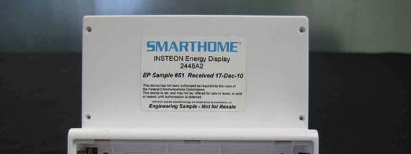
Click to zoom
Application Details
- Equipment Class
- DXT - Part 15 Low Power Transceiver, Rx Verified
- Date of Grant
- Mar 24, 2011
- Application Purpose
- Original Equipment
- Date of Application
- Mar 23, 2011
- Equipment Note
- Portable LCD Display
- Frequency Range
- 914.90000000 - 915.10000000
- Company
- Insteon Technologies, LLC
- Country
- United States
Documents & Files
Document Text
Text extracted from the exhibit documents filed with the FCC. Open a document above to read the original.
Users Manual
Page 1 of 3 Rev. 01-14-2011 Smarthome Limited Warranty – Smarthome warrants to original consumer of this product for a period of 2 years from date of purchase, this product will be free from defects in material & workmanship & will perform in substantial conformity with its Owner's Manual. Warranty shall not apply to defects caused by misuse or neglect. U.S. Patent No. 7,345,998, International patents pending © Copyright 2011 Smarthome, 16542 Millikan Ave., Irvine, CA 92606, 800-762-7845 Display options Battery level Meter 1 Cost setting Temperature setting Installation NOTE: Energy Display uses 2 AAA batteries and will provide approximately one year of use per pair. 1) Energy Display requires at least one Access Point (#2443) or dual-band INSTEON device for communication. For the best INSTEON network performance, be sure you have properly installed at least two dual-band INSTEON devices. Search for dual-band INSTEON devices at: www.smarthome.com/dualband 2) Remove the battery compartment from the rear of Energy Display 3) Observe the polarity markings, install two AAA batteries, and then replace the battery compartment door The Energy Display screen should turn on and all LCD segments should turn on After a few seconds, Energy Display should beep and its screen should be in Display Mode Energy Display should attempt to gather data. While gathering data, Energy Display should show a series of hyphens along the top of the screen. Energy Display is now ready to use. See Linking Energy Display to an INSTEON Device to begin receiving energy information about your appliances. Quick-Start Guide Energy Display – INSTEON ® In-Home Display Model: 2448A2 Introduction Energy Display reads power consumption information from devices plugged into INSTEON devices and presents current power use, average energy use per month, and average cost per month based on your monthly billing rate. NOTE: Energy Display requires an INSTEON meter device (e.g., iMete r ™ Solo). Refresh button 1/2/3 button Restart button Mode button Status LED Set button Meter 3 Meter 2 Using Energy Display Data is retrieved when: • Energy Display is first Linked to a meter device • Refresh button is tapped while Energy Display is in Display Mode • Any button is tapped in Standby Mode Energy Display will exhibit power-related information for one minute after the last button press, and then enter Standby Mode to prevent unnecessary traffic on the network and save battery energy. When in Standby Mode, no items will display on the screen except the temperature settings. Tap any button to exit Standby Mode. When Energy Display exits Standby Mode, it will return to the previous Display Mode. Display Mode NOTE: Circled text indicates blinking text on the Energy Display screen. Button Action Mode • Tap to cycle between display setting options • Instantaneous Watts used (Now | W) • Average cost per month (Avg | $/mo) • Average energy used per month (Avg | kWh/mo) • Press & hold for 3 seconds to enter Setup Mode Up N/A 1/2/3 • Tap to cycle between each meter device to be displayed (Meter 1, 2, or 3) • Press & hold for 10 seconds to reset the energy value for the currently displayed meter device (for calculating average energy used and cost/month) Refresh Tap to read current information for all meter devices Set button Press & hold for 3 seconds to Link a meter device to the current meter position on Energy Display (Meter 1, 2, or 3). See Linking Energy Display to an INSTEON Meter Device. Page 2 of 3 Rev. 01-14-2011 Smarthome Limited Warranty – Smarthome warrants to original consumer of this product for a period of 2 years from date of purchase, this product will be free from defects in material & workmanship & will perform in substantial conformity with its Owner's Manual. Warranty shall not apply to defects caused by misuse or neglect. U.S. Patent No. 7,345,998, International patents pending © Copyright 2011 Smarthome, 16542 Millikan Ave., Irvine, CA 92606, 800-762-7845 Quick-Start Guide INSTEON Energy Display *Setup Modes will automatically time out after 4 minutes. **Temperature Calibration Mode will automatically time out after 1 minute. Setup Modes NOTE: Circled text indicates blinking text on the Energy Display screen. To enter Setup Mode, press & hold the Mode button for 3 seconds. To exit Setup Mode: • Tap the Refresh button to accept the current value • Wait for Energy Display to time out and automatically accept the current value (~1 minute) • Tap the Mode button to accept the current value and move to the next Setup Mode Once Energy Display exits a setup mode, it will return the screen to Display Mode. Cost Mode Range is 0.1 to 999 cents/kWhr ($9.99/kWhr). Once the counter reaches 99.9¢, it will reset to 100¢. The default is 10.0¢. Button Action Mode Tap to cycle to the next setting mode (Temperature Format) Tap to increase the cost by 0.1¢ until cost exceeds 99.9¢. If cost is 100¢ or greater, cost increases by 1¢. Up Press & hold to continuously increase cost Tap to decrease the cost by 0.1¢ if cost is between 0.1¢ and 99.9¢. If cost is 100¢ or greater, decreases by 1¢. Down Press & hold to continuously decrease cost OK Tap to accept current Cost setting and exit Setup Mode Set button N/A Temperature Format Mode Range is 0 to 199 degrees. The default is Fahrenheit. Button Action Mode Tap to cycle to the next setting mode (Display Mode) Up Down Tap to toggle the temperature display between Celsius and Fahrenheit OK Tap to accept current Temperature Format setting and exit Setup Mode Set button N/A Linking Energy Display to an INSTEON Meter Device 1) Make sure the meter device is properly installed with the appliance you wish to monitor 2) Tap the 1/2/3 button until the desired meter position is blinking (Meter 1, 2, or 3) 3) Set Energy Display to Linking Mode* by pressing & holding the Refresh button until it beeps (3 seconds) The Energy Display Status LED should begin blinking green 4) On the meter device, press & hold the Set butto…
Text truncated - open the document above for the full version.
Test Report
This report c written cons e TE S CERT #803 803.05 ontains a total of ent of CKC Laborat FC STING 3.01, 803.02, 5, 803.06 27 pages and ma tories, Inc. INS SM Te CC Part 15 Su This test rep testing perfo of ISO/IEC 1 CKC Laborato We strive t o sound, adapt our custome processes, bu ay be reproduced Smart TEST STEON Ene MART Ener ested To The ubpart C Sec Repor Date of issu port bears th ormed herein 17025 under ories, Inc. o create long‐t tive, customer ers’ unique EM ut rather as th in full only. Partia tLabs, REPORT FO ergy Displa rgy Display e Following S ctions 15.24 rt No.: 91262 ue: January 12 e accreditatio meets the tes the applicab term, trust ba r first testing MC challenges, e reason we a al reproduction m Inc. OR ay, 2448A2 y, 4734A1 Standards: 49 and RSS 2 ‐4 2, 2011 on symbol ind st and reporti ble scope of sed relations h services. We , not as an int are in business may only be done 2 210 Issue 8 dicating that ing requireme EMC testing hips by provid embrace each terruption to . with the the ents for ding h of set Page 2of 27 Report No.: 91262‐4 TABLE OF CONTENTS Administrative Information ........................................................................................................................................... 3 Test Report Information ............................................................................................................................................ 3 Report Authorization ................................................................................................................................................. 3 Test Facility Information ............................................................................................................................................ 4 Site Registration & Accreditation Information .......................................................................................................... 4 Summary of Results ................................................................................................................................................... 5 Conditions During Testing ......................................................................................................................................... 5 Equipment Under Test ............................................................................................................................................... 6 Peripheral Devices ..................................................................................................................................................... 6 FCC Part 15 Subpart C .................................................................................................................................................... 7 15.249(a) RF Power Output ‐ Field Strength of Harmonics ....................................................................................... 7 ‐20dBc Occupied Bandwidth ................................................................................................................................... 14 Bandedge ................................................................................................................................................................. 16 15.249(d) Field Strength of Spurious Emissions ...................................................................................................... 19 RSS 210 ........................................................................................................................................................................ 24 99% Bandwidth ........................................................................................................................................................ 24 Supplemental Information .......................................................................................................................................... 26 Measurement Uncertainty ...................................................................................................................................... 26 Emissions Test Details .............................................................................................................................................. 26 Page 3of 27 Report No.: 91262‐4 ADMINISTRATIVE INFORMATION Test Report Information REPORT PREPARED FOR: REPORT PREPARED BY: SmartLabs, Inc. 16542 Millikan Ave. Irvine, CA 92606 Dianne Dudley CKC Laboratories, Inc. 5046 Sierra Pines Drive Mariposa, CA 95338 Representative: John Lockyer Project Number: 91262 Customer Reference Number: 10‐3J1222‐01 DATE OF EQUIPMENT RECEIPT: January5, 2011 DATE(S) OF TESTING: January5‐ 6, 2011 Report Authorization The test data contained in this report documents the observed testing parameters pertaining to and are relevant for only the sample equipment tested in the agreed upon operational mode(s) and configuration(s) as identified herein. Compliance assessment remains the client’s responsibility. This report may not be used to claim product endorsement by A2LA or any government agencies. This test report has been authorized for release under quality control from CKC Laboratories, Inc. Steve Behm Director of Quality Assurance & Engineering Services CKC Laboratories, Inc. Page 4of 27 Report No.: 91262‐4 Test Facility Information Our laboratories are configured to effectively test a wide variety of product types. CKC utilizes first class test equipment, anechoic chambers, data acquisition and information services to create accurate, repeatable and affordable test results. TEST LOCATION(S): CKC Laboratories, Inc. 110 Olinda Place Brea, CA 92823 Site Registration & Accreditation Information Location CB # Japan Canada FCC Brea D US0060 R‐1256, C‐1319, T‐1660 & G‐255 3082D‐2 100638 Page 5of 27 Report No.: 91262‐4 SUMMARY OF RESULTS Standard / Specification: FCC Part 15 Subpart C 15.249 and RSS‐210 Issue 8 Description Test Procedure/Method Results RF Power Output Field Strength of Harmonics FCC …
Text truncated - open the document above for the full version.
Contact Information
Applicant
John Lockyer(Suite 105-665)
Technical Contact
SmartLabs, Inc.John Lockyer
[email protected]949-221-0037
16542 Millikan Ave. · Irvine, California · United States
Test Firm
CKC Laboratories, Inc.Steve Behm
Technical Specifications
| # | Rule Parts | Frequency Range | Power Output |
|---|---|---|---|
| 1 | 15C | 914.9 MHz - 915.1 MHz | - |
Other Applications from Insteon Technologies, LLC

SBP-MS01
Nov 28, 2020Multi Sensor
Equipment Class
DXX - Part 15 Low Power Communication Device Transmitter
SBP-BC01
Sep 10, 2020Bridge Controller
Equipment Class
DSS - Part 15 Spread Spectrum Transmitter
SBP-WR01
Mar 21, 2020Smart Outlet
Equipment Class
DXX - Part 15 Low Power Communication Device Transmitter
SBP-WALL
Mar 19, 2020Smart Wall Switch
Equipment Class
DXX - Part 15 Low Power Communication Device Transmitter
SBP26632
Sep 30, 2014On/Off Outlet
Equipment Class
DXT - Part 15 Low Power Transceiver, Rx Verified