SBP2475DA1In-Line Hardwired Light Dimming Module
Insteon Technologies, LLC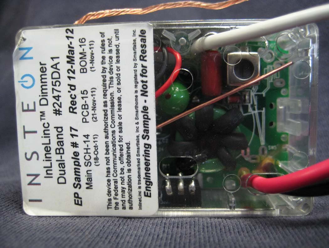
Click to zoom
Application Details
- Equipment Class
- DXT - Part 15 Low Power Transceiver, Rx Verified
- Date of Grant
- May 15, 2012
- Application Purpose
- Original Equipment
- Date of Application
- May 13, 2012
- Equipment Note
- In-Line Hardwired Light Dimming Module
- Frequency Range
- 914.90000000 - 915.10000000
- Company
- Insteon Technologies, LLC
- Country
- United States
Documents & Files
Document Text
Text extracted from the exhibit documents filed with the FCC. Open a document above to read the original.
Users Manual
April 20, 2012 In-Line Hardwired Light Dimming Module Model: 2475DA1 FCC ID: SBP2475DA1 IC: 5202A-2475DA1 The owner’s manual below may be accessed freely via the Internet with any web browser and supports the PDF format. www.smarthome.com/2475DA1.html Complies with Section 5 of FCC document 784748 D01 Labeling Part 15 18 Guidelines v07 where cautionary statements in the user manual may be provided over the Internet. On-Line Owner’s Manual Containing Cautionary FCC & IC Statements Page 1 of 14 2475DA1 - Rev: 4/20/2012 4:35 PM In-LineLinc™ Dimmer INSTEON ® In-LineLinc Dimmer, Dual-Band Owner’s Manual (#2475DA1) Page 2 of 14 2475DA1 - Rev: 4/20/2012 4:35 PM In-LineLinc Dimmer Dual-Band ................................................................................................................. 3 Features and Benefits................................................................................................................................. 3 What’s in the Box?..................................................................................................................................... 3 Installation ................................................................................................................................................... 4 Identifying the Electrical Wires in your Home............................................................................................ 4 Tools Needed ............................................................................................................................................ 4 Installing In-LineLinc Dimmer Dual-Band .................................................................................................. 5 Using In-LineLinc Dimmer Dual-Band ...................................................................................................... 6 LEDs .......................................................................................................................................................... 6 Using the ON and OFF Buttons ................................................................................................................ 6 Button Functions........................................................................................................................................ 6 Local On-Level .......................................................................................................................................... 6 Beeper Behavior.......................................................................................................................................... 7 Setting Up an INSTEON Scene .................................................................................................................. 7 Adding In-LineLinc Dimmer Dual-Band to a Scene as an INSTEON Responder ..................................... 7 Removing In-LineLinc Dimmer Dual-Band from a Scene as an INSTEON Responder............................ 7 Advanced Features ..................................................................................................................................... 8 Using In-LineLinc Dimmer Dual-Band as a Phase Bridge ........................................................................ 8 Power Restoration ..................................................................................................................................... 8 X10 Programming ....................................................................................................................................... 8 Factory Reset ............................................................................................................................................ 8 Local Ramp Rate....................................................................................................................................... 9 Specifications ............................................................................................................................................ 10 Troubleshooting ........................................................................................................................................ 13 Certification and Warranty ....................................................................................................................... 14 Certification.............................................................................................................................................. 14 FCC and Industry Canada Compliance Statement................................................................................. 14 Limited Warranty ..................................................................................................................................... 14 Limitations ............................................................................................................................................ 14 Page 3 of 14 2475DA1 - Rev: 4/20/2012 4:35 PM In-LineLinc Dimmer Dual-Band Congratulations on your purchase of the elegant, high-quality In-LineLinc Dimmer Dual-Band. In-LineLinc Dimmer Dual-Band installs in-line to provide INSTEON control of individual dimmable lighting fixtures. Additionally, In-LineLinc Dimmer Dual-Band eliminates the need for a conventional light switch, reducing the “switch sprawl” common to automation projects. You can also use In-LineLinc Dimmer Dual-Band for INSTEON signal repeating and phase bridging (like an Access Point, #2443). In-LineLinc Dimmer Dual- Band supports voltages from 100-277V, 50/60Hz and loads up to 400W, making it the perfect energy- saving, wireless controller. Features and Benefits Once installed, INSTEON setup is easy Controls incandescent loads up to 400W Supports up to 400 scene memberships Shows INSTEON setup mode activity with beeper and dual-color Status LED Communicates simultaneously over both radio frequency (RF) and the powerline Acts as an Access Point for RF-only …
Text truncated - open the document above for the full version.
ID Label/Location Info
April 20, 2012 Subject: Unit Label In-Line Hardwired Light Dimming Module Model: 2475DA1 FCC ID: SBP2475DA1 IC: 5202A-2475DA1 Specs: Width – 1.50 inches (38.1mm) Height – 1.57 inches (40mm) Surface Material: gloss white polyester face stock with a smooth, absorbent ink-receptive top coating Surface Material Thickness - .050 mm ± 10% ISO534 Base Material – Super-Calendared White Glassine Paper Base Thickness - 0.070mm ± 10% ISO534 Adhesive Base – Acrylic .025mm Thickness 24 hour 90° Peel (st,st)-FTM 2: 7.5 Service Temperature Range: -40°C~+80°C (when applied to polycarbonate) UL Recognized Listing # MH47798 Unit Label
ID Label/Location Info
April 20, 2012 In-Line Hardwired Light Dimming Module Model: 2475DA1 FCC ID: SBP2475DA1 IC: 5202A-2475DA1 Unit label placed on back of plastic case. Unit Label Location
Test Report
This report contains a total of 35 pages and may be reproduced in full only. Partial reproduction may only be done with the written consent of CKC Laboratories, Inc. SmartLabs, Inc. TEST REPORT FOR In-Line Dual-Band Hardwired Light Dimming Module, 2475DA1 Tested To The Following Standards: FCC Part 15 Subpart C Sections 15.207, 15.209, 15.249 and RSS 210 Issue 8 Report No.: 92708-4 Date of issue: April 11, 2012 This test report bears the accreditation symbol indicating that the testing performed herein meets the test and reporting requirements of ISO/IEC 17025 under the applicable scope of EMC testing for CKC Laboratories, Inc. We strive to create long-term, trust based relationships by providing sound, adaptive, customer first testing services. We embrace each of our customers’ unique EMC challenges, not as an interruption to set processes, but rather as the reason we are in business. Page 2 of 35 Report No.: 92708-4 TABLE OF CONTENTS Administrative Information ........................................................................................................................................... 3 Test Report Information ............................................................................................................................................ 3 Report Authorization ................................................................................................................................................. 3 Test Facility Information ............................................................................................................................................ 4 Site Registration & Accreditation Information .......................................................................................................... 4 Summary of Results ................................................................................................................................................... 5 Conditions During Testing.......................................................................................................................................... 5 Equipment Under Test ............................................................................................................................................... 6 Peripheral Devices ..................................................................................................................................................... 6 FCC Part 15 Subpart C .................................................................................................................................................... 7 15.31(e) Voltage Variations ....................................................................................................................................... 7 15.207 AC Conducted Emissions ................................................................................................................................ 8 15.249(a) RF Power Output ..................................................................................................................................... 15 15.249(b) Field Strength of Harmonics .................................................................................................................... 17 -20dBc Occupied Bandwidth ................................................................................................................................... 21 Bandedge ................................................................................................................................................................. 23 15.249(d) / 15.209 Field Strength of Radiated Spurious Emissions ......................................................................... 26 RSS-210 ........................................................................................................................................................................ 31 99 % Bandwidth ....................................................................................................................................................... 31 Supplemental Information .......................................................................................................................................... 34 Measurement Uncertainty ...................................................................................................................................... 34 Emissions Test Details .............................................................................................................................................. 34 Page 3 of 35 Report No.: 92708-4 ADMINISTRATIVE INFORMATION Test Report Information REPORT PREPARED FOR: REPORT PREPARED BY: SmartLabs, Inc. 16542 Millikan Ave. Irvine, CA 92606 Dianne Dudley CKC Laboratories, Inc. 5046 Sierra Pines Drive Mariposa, CA 95338 Representative: John Lockyer Project Number: 92708 Customer Reference Number: 12-3JL0117-03 DATE OF EQUIPMENT RECEIPT: April 3, 2012 DATE(S) OF TESTING: April 3-9, 2012 Report Authorization The test data contained in this report documents the observed testing parameters pertaining to and are relevant for only the sample equipment tested in the agreed upon operational mode(s) and configuration(s) as identified herein. Compliance assessment remains the client’s responsibility. This report may not be used to claim product endorsement by A2LA or any government agencies. This test report has been authorized for release under quality control from CKC Laboratories, Inc. Steve Behm Director of Quality Assurance & Engineering Services CKC Laboratories, Inc. Page 4 of 35 Report No.: 92708-4 Test Facility Information Our laboratories are configured to effectively test a wide variety of product types. CKC utilizes first class test equipment, anechoic chambers, data acquisition and information services to create accurate, repeatable and affordable test results. TEST LOCATION(S): CKC Laboratories, Inc. 110 Olinda Place Brea, CA 92823 Site R…
Text truncated - open the document above for the full version.
Contact Information
Applicant
John Lockyer(Suite 105-665)
Technical Contact
Smartlab, Inc.John Lockyer
[email protected]949-221-0037
16542 Millikan Ave. · Irivne, California · United States
Test Firm
CKC Laboratories, Inc.Steve Behm
Technical Specifications
| # | Rule Parts | Frequency Range | Power Output |
|---|---|---|---|
| 1 | 15C | 914.9 MHz - 915.1 MHz | - |
Other Applications from Insteon Technologies, LLC

SBP-MS01
Nov 28, 2020Multi Sensor
Equipment Class
DXX - Part 15 Low Power Communication Device Transmitter
SBP-BC01
Sep 10, 2020Bridge Controller
Equipment Class
DSS - Part 15 Spread Spectrum Transmitter
SBP-WR01
Mar 21, 2020Smart Outlet
Equipment Class
DXX - Part 15 Low Power Communication Device Transmitter
SBP-WALL
Mar 19, 2020Smart Wall Switch
Equipment Class
DXX - Part 15 Low Power Communication Device Transmitter
SBP26632
Sep 30, 2014On/Off Outlet
Equipment Class
DXT - Part 15 Low Power Transceiver, Rx Verified