SBP2477DSwitchLinc tm - INSTEON Dimmer Switch (Dual-Band)
Insteon Technologies, LLC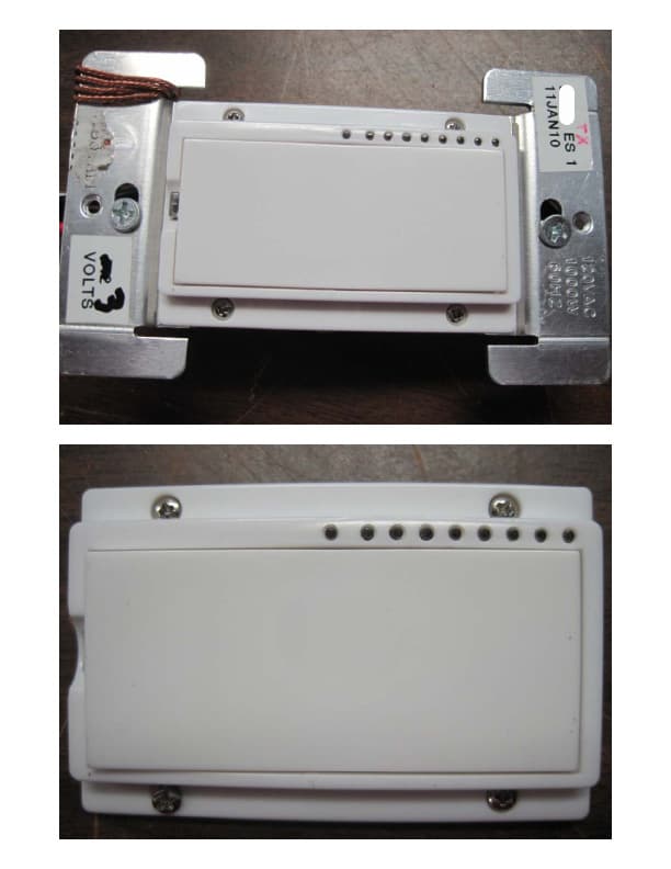
Click to zoom
Application Details
- Equipment Class
- DXT - Part 15 Low Power Transceiver, Rx Verified
- Date of Grant
- Aug 10, 2010
- Application Purpose
- Original Equipment
- Date of Application
- Aug 10, 2010
- Equipment Note
- SwitchLinc tm - INSTEON Dimmer Switch (Dual-Band)
- Frequency Range
- 914.90000000 - 915.10000000
- Company
- Insteon Technologies, LLC
- Country
- United States
Documents & Files
Document Text
Text extracted from the exhibit documents filed with the FCC. Open a document above to read the original.
Users Manual
Page 1 of 2 Rev. 04-02-2010 Quick-Start Guide SwitchLinc TM Dimmer – INSTEON ® Remote Control Dimmer Switch (Dual-Band) Model: 2477D Preparation Installation should be performed only by a qualified electrician or by a homeowner who is familiar and comfortable with electrical circuitry. If you have any questions regarding installation, we suggest consulting an electrician. If you have any questions regarding setup, contact Smarthome Tech Support. LED bar Set button Figure 1 Introduction Remotely control any light in your home at the touch of a button. Use the paddle on SwitchLinc to control other Linked INSTEON devices. Or send commands to SwitchLinc from an INSTEON Controller. SwitchLinc also works as an INSTEON signal repeater and can be used to bridge the power phases in your home (like an Access Point, #2443). Use indoors only. Using SwitchLinc Tap the paddle top to turn your light on (to its programmed On-Level and Ramp Rate) Tap the paddle bottom to turn your light off (at its programmed Ramp Rate) Press & hold the paddle top to brighten your light Press & hold the paddle bottom to dim your light Double-tap the paddle top to turn your light to full-bright instantly Double-tap the paddle bottom to turn your light off instantly Paddle bottom (OFF/DIM) Paddle top (ON/BRIGHT) Tools Needed • Phillips and Standard screwdriver • Wire cutter / stripper • Voltage tester to identify wires inside the junction box Installation (Typical, 2-Way Circuit) Note: For Multi-Way Circuit installation, refer to the Owner’s Manual. 1) At the circuit breaker or fuse panel, disable the circuit supplying power to the switch 2) Remove the faceplate from the existing switch, then unscrew the switch and pull it out from the junction box 3) Disconnect the wires from the switch you are replacing and ensure you have 1/2” of bare wire on the ends 4) To correctly identify the LINE, LOAD, NEUTRAL, and GROUND wires, enable power to the switch from the circuit breaker or fuse panel, use a line voltage meter, then turn the breaker off again. See Figure 1 to properly connect your wires to the INSTEON device. Note: Mechanical switches don’t utilize NEUTRAL wires, but they are usually available in the back of the switch box. 5) Ensure that all wire connectors are firmly attached and that there is no exposed copper except for the GROUND wire 6) Orient SwitchLinc with the LED bar at the left, gently place it into the junction box, and then screw it into place 7) Enable power to the switch from the circuit breaker or fuse panel 8) Test that SwitchLinc is working properly by turning the light on and off 9) Reinstall the faceplate Page 2 of 2 Rev. 04-02-2010 Quick-Start Guide SwitchLinc Dimmer (Dual-Band) Complete Instructions, Troubleshooting, and Tech Support Owner’s Manual: http://wiki.smarthome.com/index.php?title=2477D_Manual Call: Tech Support @ 1-800-SMARTHOME (800-762-7846) Contact Us Online: http://www.smarthome.com/contactus.html Using SwitchLinc as a Responder 1) Select an INSTEON-compatible Controller and activate its Linking Mode. You will have 4 minutes to complete the next step. 2) Press & hold the paddle top on SwitchLinc until the unit double-beeps (about 10 seconds) The top LED will flash, and then turn on solid green if the controlled light is on and solid red if the light is off 3) Confirm the Link was successful by tapping the On and Off buttons you just Linked to SwitchLinc should respond appropriately Using SwitchLinc as a Controller 1) Press & hold the paddle top until the unit beeps (about 10 seconds) The top LED will begin blinking green and the controlled light will flash You will have 4 minutes to complete the next step. 2) Select the INSTEON device you would like to control and activate its Linking Mode SwitchLinc will double-beep and its LED will stop blinking and turn on solid green if the controlled light is on or solid red if the light is off 3) Confirm the Link was successful by tapping the SwitchLinc paddle top on and off The device SwitchLinc is controlling should respond appropriately SmartLabs Limited Warranty – SmartLabs warrants to original consumer of this product for a period of 2 years from date of purchase, this product will be free from defects in material & workmanship & will perform in substantial conformity with its Owner's Manual. Warranty shall not apply to defects caused by misuse or neglect. U.S. Patent No. 7,345,998, International patents pending © Copyright 2010 SmartLabs, 16542 Millikan Ave., Irvine, CA 92606, 1-800-SMARTHOME (800-762-7846) Using SwitchLinc to Bridge Phases SwitchLinc can help bridge the phases in your home like an Access Point, allowing RF-only devices (e.g., RemoteLinc) access to power line-only devices (e.g., ApplianceLinc). For the best INSTEON network performance, it is recommended that you install at least two dual-band products. Search for dual-band INSTEON products at http://www.smarthome.com/dualband. Use the following procedure to test that the phases have been bridged. 1) Start Phase Bridging Detection Mode by tapping the SwitchLinc Set button 4 times quickly SwitchLinc will begin beeping continuously once per second and the LED will be solid green 2) Check the LED behavior of your other dual-band devices. Verify at least one of your dual-band device’s LEDs responds as follows: Your other dual-band device LED will blink green, or be bright solid white or blue 3) If none of your dual-band devices exhibit the behavior in step 2, they are on the same power phase. Try: • Following steps 1 and 2 with other dual-band devices to see if they are bridging the phases • Moving your other dual-band devices to other locations until they exhibit the desired LED behavior 4) Tap the Set button on SwitchLinc to exit Phase Bridging Detection Mode SwitchLinc will stop beeping ETL/UL Warning CAUTION - To reduce the risk of overheating and possible damage to other equipment do not install to control a receptacle, a motor-operated appliance, a fluorescent …
Text truncated - open the document above for the full version.
Cover Letter(s)
CKC Certifications Services - Confidential E10-000024-FCC EP04 1 of 13 Rev 10 EP04 CKC Certification Services Evaluation/Application Report For Application: E10-000024-FCC Date of Report: March 26, 2010 Report Number: EV10-024 CKC Certifications Services - Confidential E10-000024-FCC EP04 2 of 13 Rev 10 Written by: Randal Clark Reviewed and Approved by: Name Title Signature MarDell Kendall President * *PDF copy with approval signatures on file in QA. Revision History 7/2/03 Rev 0 Original Release 10/24/03 Rev 1 Created word template from original form. Added new section 3 Restructured document layout and required fields for new section. Added standard text for conclusion section. 3/23/04 Rev2 Restructured document to accommodate Industry Canada requirements. Formatted document into a template format. All future revision tracking will be logged in the Visual Basic Editor Notes. 12/3/04 Rev 3 History is located in the “AutoNew” module notes 1/10/04 Rev 4 Refer to AutoNew module notes for revision history. 5/17/05 Rev 5 Refer to AutoNew module notes for revision history. 2/10/06 Rev 6 Refer to AutoNew module notes for revision history. 4/11/06 Rev 7 Refer to AutoNew module notes for revision history. 2/13/07 Rev 8 Refer to AutoNew module notes for revision history. 6/23/07 Rev 9 Refer to AutoNew module notes for revision history. 5/9/08 Rev 10 Refer to AutoNew module notes for revision history. 8/7/08 Rev 11 Refer to AutoNew module notes for revision history. CKC Certifications Services - Confidential E10-000024-FCC EP04 3 of 13 Rev 10 Table of Contents 1 ADMINISTRATIVE SUMMARY ......................................................................................................... 4 2 LIST OF CKC CS PERSONNEL INVOLVED WITH APPLICATION ........................................... 5 2.1 EXEMPTED PERSONS ........................................................................................................................... 5 2.2 REVIEWERS AND DECISION MAKERS .................................................................................................. 5 3 CONCLUSIONS / RECOMMENDATIONS......................................................................................... 6 3.1 US RADIO EQUIPMENT AUTHORIZATION ............................................................................................ 6 4 US APPLICATION FOR RADIO EQUIPMENT AUTHORIZATION ............................................. 7 4.1 APPLICATION CHECKLIST ................................................................................................................... 7 4.2 APPLICATION INFORMATION .............................................................................................................. 7 APPENDIX A ................................................................................................................................................. 10 APPENDIX Z ................................................................................................................................................. 12 CKC Certifications Services - Confidential E10-000024-FCC EP04 4 of 13 Rev 10 1 Administrative Summary Report Issued By: CKC Certification Services 4933 Sierra Pines Dr. Mariposa, CA 95338 Phone: (209) 742-2378 Fax: (866) 779-9776 International Fax: +1 858-300-5341 Applicant Information: SmartLabs, Inc. 16542 Millikan Ave. Irvine, CA 92606 USA Phone: 949-221-0037 Fax: 949-221-9241 Description of Services: Evaluation of SwitchLinc™ - INSTEON Dimmer Switch (Dual- Band) for equipment authorization according to the applicable rules as defined by the services requested. Evaluation Procedure Documents: TCB03 TCB35 Certification Numbers FCC ID: IC: iDA: EU: SBP2477D WO Number: 90456 CKC Certifications Services - Confidential E10-000024-FCC EP04 5 of 13 Rev 10 2 List of CKC CS Personnel Involved with Application It is CKC Certification Services policy that each decision on certification is taken by a person(s) different from those who carried out the evaluation. No person acting as an agent or technical or non-technical contact (i.e. as listed on the 731 Form) shall perform any certification functions. Refer also to procedures TCB04 Section 3 (Certification Committee Operating Procedures) Any person employed by CKC Certification Services or by CKC Laboratories who performs functions for CKC Certification Services who has a direct involvement with the applicant, such as a person acting as an agent for the applicant or a person who has performed testing for this application is exempt from the certification decision and must have their name listed below. Persons performing multiple functions need only be listed once. Note: Evaluation may be performed by persons involved with other functions, however certification decision may not. 2.1 Exempted Persons Function Name Comments Non-Technical Contact Jessina Hunter Technical Contact Jessina Hunter Agent Jessina Hunter Test Engineer Shaminderjit Hundal CKC - Brea Consultant Other 2.2 Reviewers and Decision Makers All persons responsible for this application and their role within the evaluation are to be listed. Function Name Comments Admin Evaluator(s) Randal Clark Technical Evaluator(s) Randal Clark Person(s) issuing recommendataion Certifier(s) Amrinder Brar Person(s) issuing certification decision CKC Certifications Services - Confidential E10-000024-FCC EP04 6 of 13 Rev 10 3 Conclusions / Recommendations 3.1 US Radio Equipment Authorization Results of evaluation for Certification pursuant to the procedures outlined in 47 CFR Part 2 for a Grant of Equipment Authorization to be issued by CKC Certification Services as a TCB acting under the authority of the Federal Communications Commission: Approval: The review of this application and all the exhibits it contains demonstrate compliance to the applicable regulations set forth by the FCC for a grant of equipment authorization. It is my recommendation that this application be approved. CKC Certifications Services -…
Text truncated - open the document above for the full version.
Test Report
This report contains a total of 39 pages and may be reproduced in full only. Partial reproduction may only be done with the written consent of CKC Laboratories, Inc. SmartLabs, Inc. TEST REPORT FOR SwitchLinc™ ‐ INSTEON Dimmer Switch (Dual‐Band), 2477D Tested To The Following Standards: FCC Part 15 Subpart C Sections 15.207 & 15.249 and RSS‐210 Version 7 Report No.: 90456‐4 Date of issue: March 8, 2010 TESTING CERT #803.01, 803.02, 803.05, 803.06 This test report bears the accreditation symbol indicating that the testing performed herein meets the test and reporting requirements of ISO/IEC 17025 under the applicable scope of EMC testing for CKC Laboratories, Inc. We strive to create long‐term, trust based relationships by providing sound, adaptive, customer first testing services. We embrace each of our customers’ unique EMC challenges, not as an interruption to set processes, but rather as the reason we are in business. Page 2of 39 Report No.: 90456‐4 TABLE OF CONTENTS Administrative Information ........................................................................................................................................... 3 Test Report Information ............................................................................................................................................ 3 Report Authorization ................................................................................................................................................. 3 Test Facility Information ............................................................................................................................................ 4 Site Registration & Accreditation Information .......................................................................................................... 4 Summary of Results ................................................................................................................................................... 5 Conditions During Testing ......................................................................................................................................... 5 Equipment Under Test ............................................................................................................................................... 6 Peripheral Devices ..................................................................................................................................................... 6 FCC Part 15 Subpart C .................................................................................................................................................... 7 Temperature And Humidity During Testing............................................................................................................... 7 15.31(e) Voltage Variation ......................................................................................................................................... 7 15.31(m) Number Of Channels .................................................................................................................................. 7 15.33(a) Frequency Ranges Tested ............................................................................................................................ 7 15.203 Antenna Requirements .................................................................................................................................. 7 EUT Operating Frequency .......................................................................................................................................... 7 15.207 AC Conducted Emissions................................................................................................................................ 8 2.1046/15.249(a) Field Strength of Fundamental ................................................................................................... 16 2.1049 Occupied Bandwidth.................................................................................................................................... 19 2.1053/15.249(a) Field Strength of Harmonics ....................................................................................................... 22 2.1053/2.249(d) Field Strength of Spurious Emissions ............................................................................................ 26 Band Edge ................................................................................................................................................................ 32 99% Bandwidth/RSS‐210 ......................................................................................................................................... 35 Supplemental Information .......................................................................................................................................... 38 Measurement Uncertainty ...................................................................................................................................... 38 Emissions Test Details .............................................................................................................................................. 38 Page 3of 39 Report No.: 90456‐4 ADMINISTRATIVE INFORMATION Test Report Information REPORT PREPARED FOR: REPORT PREPARED BY: SmartLabs, Inc. 16542 Millikan Ave. Irvine, CA 92606 Dianne Dudley CKC Laboratories, Inc. 5046 Sierra Pines Drive Mariposa, CA 95338 Representative: John Lockyer Project Number: 90456 Customer Reference Number: 10‐3JL0210‐01 DATE OF EQUIPMENT RECEIPT: February 12,2010 DATE(S) OF TESTING: February 12 –March 3, 2010 Report Authorization The test data contained in this report documents the observed testing parameters pertaining to and are relevant for only the sample equipment tested in the agreed upon operational mode(s) and configuration(s) as identified herein. Compliance assessment remains the client’s responsibility. This report may…
Text truncated - open the document above for the full version.
Contact Information
Applicant
John Lockyer(Suite 105-665)
Technical Contact
CKC Certification Services, LLCJessina Hunter
[email protected]209-966-5240
5046 Sierra Pines Dr. · Mariposa, California · United States
Test Firm
CKC Laboratories, Inc.Steve Behm
Technical Specifications
| # | Rule Parts | Frequency Range | Power Output |
|---|---|---|---|
| 1 | 15C | 914.9 MHz - 915.1 MHz | - |
Other Applications from Insteon Technologies, LLC

SBP-MS01
Nov 28, 2020Multi Sensor
Equipment Class
DXX - Part 15 Low Power Communication Device Transmitter
SBP-BC01
Sep 10, 2020Bridge Controller
Equipment Class
DSS - Part 15 Spread Spectrum Transmitter
SBP-WR01
Mar 21, 2020Smart Outlet
Equipment Class
DXX - Part 15 Low Power Communication Device Transmitter
SBP-WALL
Mar 19, 2020Smart Wall Switch
Equipment Class
DXX - Part 15 Low Power Communication Device Transmitter
SBP26632
Sep 30, 2014On/Off Outlet
Equipment Class
DXT - Part 15 Low Power Transceiver, Rx Verified