SBP2477SADual-Band Load Controller with Phase Coupler
Insteon Technologies, LLC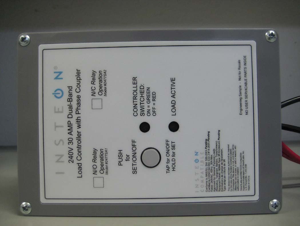
Click to zoom
Application Details
- Equipment Class
- DXT - Part 15 Low Power Transceiver, Rx Verified
- Date of Grant
- Feb 18, 2010
- Application Purpose
- Original Equipment
- Date of Application
- Feb 11, 2010
- Equipment Note
- Dual-Band Load Controller with Phase Coupler
- Frequency Range
- 914.90000000 - 915.10000000
- Company
- Insteon Technologies, LLC
- Country
- United States
Documents & Files
Document Text
Text extracted from the exhibit documents filed with the FCC. Open a document above to read the original.
Users Manual
Page 1 of 2 Rev. 02-02-2010 SmartLabs Limited Warranty – SmartLabs warrants to original consumer of this product for a period of 2 years from date of purchase, this product will be free from defects in material & workmanship & will perform in substantial conformity with its Owner's Manual. Warranty shall not apply to defects caused by misuse or neglect. U.S. Patent No. 7,345,998, International patents pending © Copyright 2010 SmartLabs, 16542 Millikan Ave., Irvine, CA 92606, 1-800-SMARTHOME (800-762-7846) Set button Installation 1) At the circuit breaker or fuse panel, disable the circuit supplying power to the electrical junction box that is wired to the appliance you wish to control with 240V Load Controller 2) Remove the cover of the junction box and disconnect the two supply lines coming from the circuit breaker, ensuring that you have ½” bare and clean copper wire on the ends. 3) See Figure 1 on the next page to properly connect 240V Load Controller to your appliance and the junction box. Connect the 240V Load Controller wires to the wires of the same color on your appliance and junction box wherever possible. 4) Ensure that all wire connectors are firmly attached and that there is not exposed copper except for the GROUND wire 5) Enable power to the junction box from the circuit breaker or fuse panel 6) Test that 240V Load Controller is working properly by pressing the Set button to toggle your appliance off, and then on Quick-Start Guide INSTEON ® 240V 30 AMP Load Controller (Dual-Band) Models: 2477SA1 – Normally Open Relay 2477SA2 – Normally Closed Relay Preparation Because this product involves high voltage levels, it is recommended that installation be performed only by a qualified electrician or by a homeowner who is extremely knowledgeable and familiar with electrical circuitry. Please take an extra level of precaution when installing this product. If you have any questions regarding installation, we suggest consulting an electrician. Tools Needed • Screwdriver (to remove cover of junction box) • Wire cutter / stripper • Various tools to mount 240V Load Controller to a wall Introduction Remotely control your appliances that run on voltages between 120 and 240 volts, up to 30 Amps. Weatherproof case allows for use with appliances located outdoors. Load Active LED Status LED Using 240V Load Controller Use the Set button on 240V Load Controller to toggle the attached load on and off The Status LED will be solid green when the attached load is on and solid red when the load is off The Load Active LED will be solid amber or green as long as the appliance is wired to 240V Load Controller Page 2 of 2 Rev. 02-02-2010 SmartLabs Limited Warranty – SmartLabs warrants to original consumer of this product for a period of 2 years from date of purchase, this product will be free from defects in material & workmanship & will perform in substantial conformity with its Owner's Manual. Warranty shall not apply to defects caused by misuse or neglect. U.S. Patent No. 7,345,998, International patents pending © Copyright 2010 SmartLabs, 16542 Millikan Ave., Irvine, CA 92606, 1-800-SMARTHOME (800-762-7846) Quick-Start Guide INSTEON 240V Load Controller (Dual-Band) Complete Instructions, Troubleshooting, and Tech Support Owner’s Manual: http://wiki.smarthome.com/index.php?title=2477SA_Manual Call: Tech. Support @ 1-800-SMARTHOME (800-762-7846) Contact Us Online: http://www.smarthome.com/contactus.html Linking 240V Load Controller as a Responder to an INSTEON Controller 1) Select the INSTEON-compatible Controller you would like to use to control 240V Load Controller and set it to Linking Mode. (For most Controllers, press & hold the On or Scene button for 10 seconds, or the Set button for 3 seconds.) You will have 4 minutes to complete the next step. 2) Press & hold the Set button on 240V Load Controller until the unit double-beeps (about 3 seconds) The 240V Load Controller Status LED will turn on solid green if the attached load is on or solid red if the attached load is off 3) Test that Linking was successful by tapping the On/Off buttons on your Controller you just Linked to 240V Load Controller 240V Load Controller should respond appropriately FCC Compliance Statement This device complies with FCC Rules Part 15.Operation is subject to 2 conditions: (1) This device may not cause harmful interference, and (2) This device must accept any interference that may be received or that may cause undesired operation. The digital circuitry of this device has been tested and found to comply with the limits for a Class B digital device, pursuant to Part 15 of the FCC Rules. These limits are designed to provide reasonable protection against harmful interference in residential installations. This equipment generates, uses, and can radiate radio frequency energy and, if not installed and used in accordance with the instructions, may cause harmful interference to radio and television reception. However, there is no guarantee that interference will not occur in a particular installation. If this device does cause such interference, which can be verified by turning the device off and on, the user is encouraged to eliminate the interference by one or more of the following measures: • Re-orient or re-locate the receiving antenna of the device experiencing the interference • Increase the distance between this device and the receiver • Connect the device to an AC outlet on a circuit different from the one that supplies power to the receiver • Consult the dealer or an experienced radio/TV technician WARNING! Changes or modifications to this unit not expressly approved by the party responsible for compliance could void the user's authority to operate the e quipment.
Cover Letter(s)
Non-Conformities FCC ID : SBP2477SA (CKC CS Ref # E10-000013-FCC-01) The items listed below represent requests for information following review of this application for certification under United S tates (FCC) regulations. Further question may arise pending review of responses to these items. OK ID # Non-Conformity or Comment Subm itted Response Respondent / Date of Response X C 1 Please confirm that the verification testing for the AC power line, carrier current system portion of this equipment has been performed , or provide a statement that the testing will be performed. Provided statement that we will perform and verify carried current test on the product in the future. John Lockyer 2/11/10 X C 2 The equipment operat es with two antennas, do both antennas operate simultaneously? The unit does operate with the two antennas simultaneously in all modes. John Lockyer 2/11/10 X TL 3 Please provide information on vo ltage variations in accordance with 15.31(e). Information regarding section 15.31(e) can be found on page 7 of the report. Stuart Yamamoto 2/11/10 4 5 6 The items indicated above must be submitted before processing can continue on the referenced application. Failure to provide t he requested information within 60 days may result in application dismissal pursuant to Section 2.917(c) and forfeiture of the filing fee pursuant to Se ction 1.1106. How to read the table: OK column indicates closure by CKC CS. ID column is for use with Agents to assist in identifying the probable source for closure. A – Application issue TL – Test lab issue C – Client issue R – Retesting may be necessary # column indicates unique or separate non-conformity items (note some items may be related). Non-Conformity or Comment column indicates the evaluators specific question or comment. Submitted response column indicates the response or a summary of the response provided. Respondent / Date of Response column indicates the responding party or agent and the date of the response was either received or logged.
Test Report
This report contains a total of 38 pages and may be reproduced in full only. Partial reproduction may only be done with the written consent of CKC Laboratories, Inc. SmartLabs, Inc. TEST REPORT FOR INSTEON 240V 30 AMP LOAD CONTROLLER (Dual‐Band) MODEL: 2477SA1 Tested To The Following Standards: FCC PART 15 SUBPART C SECTIONS 15.207 & 15.249 AND RSS‐210 VERSION 7 Report No.: 90412‐3 Date of issue: February 5, 2010 TESTING CERT #803.01, 803.02, 803.05, 803.06 This test report bears the accreditation symbol indicating that the testing performed herein meets the test and reporting requirements of ISO/IEC 17025 under the applicable scope of EMC testing for CKC Laboratories, Inc. We strive to create long‐term, trust based relationships by providing sound, adaptive, customer first testing services. We embrace each of our customers’ unique EMC challenges, not as an interruption to set processes, but rather as the reason we are in business. Page 2of 38 Report No.: 90412‐3 TABLE OF CONTENTS Administrative Information .......................................................................................................................... 3 Test Report Information ............................................................................................................................................ 3 Report Authorization ................................................................................................................................................. 3 Test Facility Information ............................................................................................................................................ 4 Site Registration & Accreditation Information .......................................................................................................... 4 Summary of Results ................................................................................................................................................... 5 Conditions During Testing ......................................................................................................................................... 5 Equipment Under Test ............................................................................................................................................... 6 Peripheral Devices ..................................................................................................................................................... 6 FCC Part 15 Subpart C ................................................................................................................................... 7 Temperature And Humidity During Testing............................................................................................................... 7 15.31(e) Voltage Variation ......................................................................................................................................... 7 15.31(m) Number Of Channels .................................................................................................................................. 7 15.33(a) Frequency Ranges Tested ............................................................................................................................ 7 15.203 Antenna Requirements .................................................................................................................................. 7 EUT Operating Frequency .......................................................................................................................................... 7 15.207 AC Conducted Emissions................................................................................................................................ 8 15.249(a)‐ Field Strength of Fundamental ............................................................................................................... 16 15.249(a) ‐ Field Strength of Harmonics .................................................................................................................. 20 15.249(d) ‐ Field Strength of Spurious Radiation ..................................................................................................... 24 FCC 2.1049 ‐ Occupied Bandwidth .......................................................................................................................... 29 Band Edge Compliance ............................................................................................................................................ 31 RSS‐210 99% ‐ Bandwidth ....................................................................................................................................... 34 Supplemental Information .......................................................................................................................... 37 Measurement Uncertainty ...................................................................................................................................... 37 Emissions Test Details .............................................................................................................................................. 37 Page 3of 38 Report No.: 90412‐3 ADMINISTRATIVE INFORMATION Test Report Information REPORT PREPARED FOR: REPORT PREPARED BY: SmartLabs, Inc. 16542 Millikan Ave. Irvine, CA 92606 Dianne Dudley CKC Laboratories, Inc. 5046 Sierra Pines Drive Mariposa, CA 95338 Representative: John Lockyer Project Number: 90412 Customer Reference Number: 10‐3JL0127‐01 DATE OF EQUIPMENT RECEIPT: February1, 2010 DATE(S) OF TESTING: February1, 2010 Report Authorization The test data contained in this report documents the observed testing parameters pertaining to and are relevant for only the sample equipment tested in the agreed upon operational mode(s) and configuration(s) as identified herein. Compliance assessment remains the client’s responsibility. This report may not be used to claim product endorsement by A…
Text truncated - open the document above for the full version.
Contact Information
Applicant
John Lockyer(Suite 105-665)
Technical Contact
CKC Certification Services, LLCJessina Hunter
[email protected]209-966-5240
5046 Sierra Pines Dr. · Mariposa, California · United States
Test Firm
CKC Laboratories, Inc.Steve Behm
Technical Specifications
| # | Rule Parts | Frequency Range | Power Output |
|---|---|---|---|
| 1 | 15C | 914.9 MHz - 915.1 MHz | - |
Other Applications from Insteon Technologies, LLC

SBP-MS01
Nov 28, 2020Multi Sensor
Equipment Class
DXX - Part 15 Low Power Communication Device Transmitter
SBP-BC01
Sep 10, 2020Bridge Controller
Equipment Class
DSS - Part 15 Spread Spectrum Transmitter
SBP-WR01
Mar 21, 2020Smart Outlet
Equipment Class
DXX - Part 15 Low Power Communication Device Transmitter
SBP-WALL
Mar 19, 2020Smart Wall Switch
Equipment Class
DXX - Part 15 Low Power Communication Device Transmitter
SBP26632
Sep 30, 2014On/Off Outlet
Equipment Class
DXT - Part 15 Low Power Transceiver, Rx Verified