SBP2634222On/Off Outdoor Module
Insteon Technologies, LLC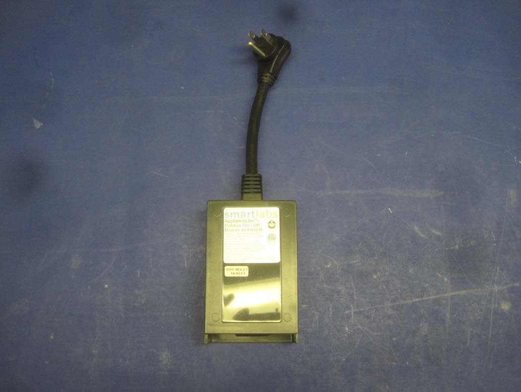
Click to zoom
Application Details
- Equipment Class
- DXT - Part 15 Low Power Transceiver, Rx Verified
- Date of Grant
- Oct 31, 2012
- Application Purpose
- Original Equipment
- Date of Application
- Oct 31, 2012
- Equipment Note
- On/Off Outdoor Module
- Frequency Range
- 914.90000000 - 915.10000000
- Company
- Insteon Technologies, LLC
- Country
- United States
Documents & Files
Document Text
Text extracted from the exhibit documents filed with the FCC. Open a document above to read the original.
Users Manual
Quick Start Guide INSTEON ® On/Off Outdoor Module Model: 2634-222 Introduction On/Off Outdoor Module allows you to remotely control any appliance/device outside your home at the touch of a button while retaining local control via load sensing (see Owner’s Manual). Can be used with incandescent lamps up to 1800 Watts and inductive loads up to 15 Amps. Installing On/Off Outdoor Module 1) Plug appliance/device (also called the load) you want to control into On/Off Outdoor Module outlet 2) Plug On/Off Outdoor Module into unswitched wall outlet Status LED will turn on solid green The load will turn on. (If load does not turn on, tap Set button.) 3) Allow On/Off Outdoor Module to hang down from outlet (see image) Make On/Off Outdoor Module a Responder 1) Press and hold controller Set button until it beeps Controller LED will start blinking green You will have four minutes to complete the next steps before linking mode times out 2) Use On/Off Module Set button to adjust load to desired level (on or off) 3) Press and hold On/Off Module Set button until it double-beeps Controller will double-beep and its LED will stop blinking 4) Test link by tapping controller button on and off Load connected to On/Off Module will respond appropriately Make On/Off Outdoor Module a Controller 1) Press and hold On/Off Module Set button until it beeps On/Off Module LED will start blinking green 2) Adjust responder to desired brightness state (such as on, 50% or even off) 3) Press and hold responder Set button until it double-beeps On/Off Module LED will stop blinking 4) Test by tapping On/Off Module Set button to turn on/off Responder will respond appropriately Owner’s Manual and Tech Support Owner’s Manual and current Quick Start Guide: http://www.insteon.com/support Call: INSTEON Support Line at 800-762-7845 FCC Compliance This device complies with FCC Rules and Industry Canada license-exempt RSS standard(s). Operation is subject to the following two conditions: (1) this device may not cause harmful interference, and (2) this device must accept any interference, including interference that may cause undesired operation of the device. Le present appareil est conforme aux CNR d'Industrie Canada applicables aux appareils radio exempts de licence. L'exploitation est autorise aux deux conditions suivantes: (1) l'appareil ne doit pas produire de brouillage, et (2) l'utilisateur de l'appareil doit accepter tout brouillage radiolectrique subi, mme si le brouillage est susceptible d'en compromettre le fonctionnement. The digital circuitry of this device has been tested and found to comply with the limits for a Class B digital device, pursuant to Part 15B of the FCC Rules. These limits are designed to provide reasonable protection against harmful interference in residential installations. This equipment generates, uses, and can radiate radio frequency energy and, if not installed and used in accordance with the instructions, may cause harmful interference to radio and television reception. However, there is no guarantee that interference will not occur in a particular installation. If this device does cause such interference, which can be verified by turning the device off and on, the user is encouraged to eliminate the interference by one or more of the following measures: - Re-orient or relocate the receiving antenna of the device experiencing the interference - Increase the distance between this device and the receiver - Connect the device to an AC outlet on a circuit different from the one that supplies power to the receiver - Consult the dealer or an experienced radio/TV technician WARNING: Changes or modifications to this device not expressly approved by the party responsible for compliance could void the user’s authority to operate the equipment. Outlet Status LED Set button
ID Label/Location Info
October 20, 2012 Subject: Unit Label On/Off Outdoor Module Model: 2634-222 FCC ID: SBP2634222 IC: 5202A-2634222 Specs: Width – 3.19 inches (81mm) Height – 1.57 inches (40mm) Suitable where exposed indoors to high humidity or occasionally exposed to water. Maximum temperature rating 80 C (176 F) Minimum temperature rating -23 C (-10 F) UL Recognized Listing # MH13600 Unit Label
ID Label/Location Info
October 22, 2012 On/Off Outdoor Module Model: 2634-222 FCC ID: SBP2634222 IC: 5202A-2634222 Label Size: 81mm x 40mm Manufacturing date code, revision, and ID number placed on unit label Unit label placed on back of plastic case. Unit Label Location
Test Report
This report contains a total of 35 pages and may be reproduced in full only. Partial reproduction may only be done with the written consent of CKC Laboratories, Inc. SmartLabs, Inc. TEST REPORT FOR On/Off Outdoor Module Model: 2634-222 Tested To The Following Standards: FCC Part 15 Subpart C Sections 15.249 and RSS 210 Issue 8 Report No.: 93569-3 Date of issue: October 18, 2012 This test report bears the accreditation symbol indicating that the testing performed herein meets the test and reporting requirements of ISO/IEC 17025 under the applicable scope of EMC testing for CKC Laboratories, Inc. We strive to create long-term, trust based relationships by providing sound, adaptive, customer first testing services. We embrace each of our customers’ unique EMC challenges, not as an interruption to set processes, but rather as the reason we are in business. Page 2 of 35 Report No.: 93569-3 TABLE OF CONTENTS Administrative Information ........................................................................................................................................... 3 Test Report Information ............................................................................................................................................ 3 Report Authorization ................................................................................................................................................. 3 Test Facility Information ............................................................................................................................................ 4 Site Registration & Accreditation Information .......................................................................................................... 4 Summary of Results ................................................................................................................................................... 5 Conditions During Testing.......................................................................................................................................... 5 Equipment Under Test ............................................................................................................................................... 6 Peripheral Devices ..................................................................................................................................................... 6 FCC Part 15 Subpart C .................................................................................................................................................... 7 15.31(e) Voltage Variations ....................................................................................................................................... 7 15.207 AC Conducted Emissions ................................................................................................................................ 9 15.249(a) RF Power Output ..................................................................................................................................... 16 -20dBc Occupied Bandwidth / RSS-210 99% Bandwidth ......................................................................................... 19 Bandedge ................................................................................................................................................................. 22 15.249(d) Radiated Spurious Emissions ................................................................................................................... 27 Supplemental Information .......................................................................................................................................... 34 Measurement Uncertainty ...................................................................................................................................... 34 Emissions Test Details .............................................................................................................................................. 34 Page 3 of 35 Report No.: 93569-3 ADMINISTRATIVE INFORMATION Test Report Information REPORT PREPARED FOR: REPORT PREPARED BY: SmartLabs, Inc. 16542 Millikan Ave. Irvine, CA 92606 Dianne Dudley CKC Laboratories, Inc. 5046 Sierra Pines Drive Mariposa, CA 95338 Representative: John Lockyer Project Number: 93569 Customer Reference Number: 12-3JL0926 DATE OF EQUIPMENT RECEIPT: October 16, 2012 DATE(S) OF TESTING: October 16, 2012 Report Authorization The test data contained in this report documents the observed testing parameters pertaining to and are relevant for only the sample equipment tested in the agreed upon operational mode(s) and configuration(s) as identified herein. Compliance assessment remains the client’s responsibility. This report may not be used to claim product endorsement by A2LA or any government agencies. This test report has been authorized for release under quality control from CKC Laboratories, Inc. Steve Behm Director of Quality Assurance & Engineering Services CKC Laboratories, Inc. Page 4 of 35 Report No.: 93569-3 Test Facility Information Our laboratories are configured to effectively test a wide variety of product types. CKC utilizes first class test equipment, anechoic chambers, data acquisition and information services to create accurate, repeatable and affordable test results. TEST LOCATION(S): CKC Laboratories, Inc. 110 Olinda Place Brea, CA 92823 Site Registration & Accreditation Information Location CB # Taiwan Canada FCC Japan Brea A US0060 SL2-IN-E-1146R 3082D-1 90473 R-2945 C-3248 T-1572 Page 5 of 35 Report No.: 93569-3 SUMMARY OF RESULTS Standard / Specification: FCC Part 15 Subpart C 15.249 and RSS 210 Issue 8 Description Test Procedure/Method Results Voltage Variation FCC Part 15 Subpart C Section 15.31(e) Pass Conducted Emissions FCC Part 15 Subpart C Section 15.207 / ANSI C63.4 (2003) Pass RF Power Output FCC Part 15 Subpart C Section 15.249(a) Pass -20dBc / 99% Occupied Bandwi…
Text truncated - open the document above for the full version.
Contact Information
Applicant
John Lockyer(Suite 105-665)
Technical Contact
Test Firm
CKC Laboratories, Inc.Steve Behm
Technical Specifications
| # | Rule Parts | Frequency Range | Power Output |
|---|---|---|---|
| 1 | 15C | 914.9 MHz - 915.1 MHz | - |
Other Applications from Insteon Technologies, LLC

SBP-MS01
Nov 28, 2020Multi Sensor
Equipment Class
DXX - Part 15 Low Power Communication Device Transmitter
SBP-BC01
Sep 10, 2020Bridge Controller
Equipment Class
DSS - Part 15 Spread Spectrum Transmitter
SBP-WR01
Mar 21, 2020Smart Outlet
Equipment Class
DXX - Part 15 Low Power Communication Device Transmitter
SBP-WALL
Mar 19, 2020Smart Wall Switch
Equipment Class
DXX - Part 15 Low Power Communication Device Transmitter
SBP26632
Sep 30, 2014On/Off Outlet
Equipment Class
DXT - Part 15 Low Power Transceiver, Rx Verified