SBP28422INSTEON Wireless Motion Sensor
Insteon Technologies, LLC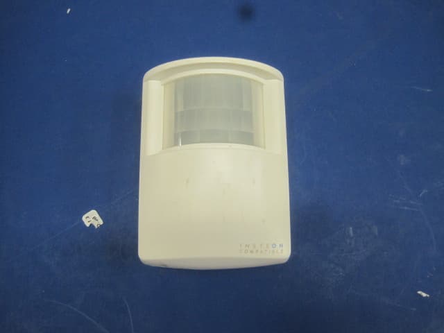
Click to zoom
Application Details
- Equipment Class
- DXT - Part 15 Low Power Transceiver, Rx Verified
- Date of Grant
- Apr 29, 2012
- Application Purpose
- Original Equipment
- Date of Application
- Apr 24, 2012
- Equipment Note
- INSTEON Wireless Motion Sensor
- Frequency Range
- 914.90000000 - 915.10000000
- Company
- Insteon Technologies, LLC
- Country
- United States
Documents & Files
Document Text
Text extracted from the exhibit documents filed with the FCC. Open a document above to read the original.
Users Manual
BEST LOCATIONS Select a detector location that will provide the required coverage. Keep the following potential problems in mind: 1. Reflective surfaces - Do not aim the detector at reflective surfaces such as mirrors or windows. This may distort the coverage pattern or reflect sunlight directly onto the detector. 2. Air flow - Avoid locations that are subject to direct high air flow, such as near an air duct outlet. 3. Moisture - Do not place the detector ne ar sources of steam or oil. 4. Sunlight - Do not aim the detector where it will receive direct or reflected (mirror) sunlight. 5. Obstruction - Do not place the detector near large objects (such as plants or filing cabinets) that will limit or block sensor coverage. 6. Pet rejection - Do not aim the detector at a stairway to which a pet has access. Do not place furniture or objects higher than what a pet can climb onto (about 3 ft/0.9 m) or closer than 6 ft/1.8 m away from the detector. 7. Fireplace - Do not place the detector near a fireplace as the light and heat may interfere with Motion Sensor’s detection ability. 8. Snow/ice – Snow or ice on the Fresnel lens may interfere with Motion Sensor’s detection ability. 9. Dirt – Dirt on the Fresnel lens may interfere with Motion Sensor’s detection ability. 6. LOCATION TIPS INSERT BATTERY Use a small Phillips head screwdriver to remove screw and cover from battery compartment on back of unit. A ttach the included 9-volt battery. Do not replace compartment cover until instru cted to do so later in this guide. Wait 5 minutes for the circuit to stabiliz e. To confirm unit is functioning, tap the Set button a couple of times while watching the front of the unit. Each time you tap the Set button, a red LED behind the sensor lens will flash. Don’t worry if the LED flashes when you are not tapping the Set button; it is simply indicating that motion is being detected. (Close-up of battery compartment) ACCESS POINTS Motion Sensor requires at least one INSTEON Access Point (#2443) or other dual-band product installed in your home. To confirm the Motion Sensor is within RF range of your Access Point, have a friend watch the LED on the side of your Access Point while you tap the Set button on the Sensor (while holding it where you plan to install it). Access Point’s LED will flash a couple times every time you tap the Set button if it is within range. Indoor/Outdoor INSTEON™ Motion Sensor Model #2842-2 1. INTRODUCTION The INSTEON Motion Sensor is an indoor/outdoor motion sensor that will turn INSTEON controlled lights on and off in response to movement around your home. The sensor also contains a photocell, allowing you to configure the unit to operate your lights only at night. Pair the Motion Sensor with INSTEON software for almost limitle ss device automation possibilities. In this package you will find the Motion Sensor, a 9V battery, a swivel mount and two screws. Motion Sensor 9V Battery Swivel Mount 2- 3x18 Screws 3. SETUP 4. SETUP INSTEON DEVICE CONTROL LINKING TO INSTEON RESPONDERS 1. Press and hold the Set button on Mo tion Sensor for 5 seconds (until red LED behind sensor lens begins blinking steadily.) You now have 4 minutes to complete step 2) 2. Press and hold the Set button 1 for 5 seconds on the INSTEON responder you would like the Motion Sensor to control (its LED may blink). 3. The Motion Sensor LED will stop blinking (if not, try step 2 again). 4. Test by tapping the Set button on Motion Sensor. Each tap should toggle the device you linked on and off. (The Motion Sensor LED will flash each time the Set button is tapped.) 5. Repeat this procedure for up to 32 responders. 1 For multi-button responders (e.g., KeypadLinc™), tap the button you wish to control before pressing and holding its Set button. 8 . AD JUS T DETE C TI O N ARE A AIMING AND SENSITIVITY 1. Tap the Set button on Motion Sensor until the linked responder(s) turn OFF. 2. Within 10 seconds, walk far out of detection area. 3. Wait 20 seconds. 4. Walk into and near your detection area. Your linked responders will turn ON (LED will flash upon initial motion, then once every 8 seconds during motion). a. If LED does not flash while you are moving within the desired detection area, readjust Sensor (usually means pointing the Sensor upward) b. If LED flashes while you’re moving outside detection area i. Readjust Sensor to dec rease range (usually means aiming the Sensor downward) ii. If aiming sensor does not generate desired results place jumper 1 on both pins (see SETUP MODES section). Set button 2. OPERATION WHEN MOTION IS SENSED 1. When motion is sensed the Motion Sensor will send an ON command to up to 30 linked INSTEON responders and flash its LED (unless it is daytime and unit is in night-only mode). 2. Sensor will begin its automatic countdown. 3. Whenever motion is sensed during countdown, the countdown will be reset to easily allow you to create “occupied” versus “unoccupied” modes for your home. 4. When countdown expires the Sensor will send an OFF command to all linked responders (unless it is in ON-only mode). APPLICATIONS 1. Turn on driveway or front step lights when visitors approach. 2. Have your fountain always on when you are around (and off when you are away). 3. Save money by having HVAC and lighting automatically go into energy savings mode when no one is around. MOUNTING (See Location Tips for help) 1. Use the two small screws (include d) to secure the swivel mounting bracket at your desired location. 2. Slide Motion Sensor onto the swivel mounting bracket (sliding to the right) until you hear a click. 3. Aim Motion Sensor towards the area in which you wish to detect motion (detection area). 4. Test by walking through the area. Linked responders should turn ON when motion is sensed and OFF one minute after last motion sensed. 7. MOUNT SENSOR 5. DETECTING ARE A 11. TR OU BLE S H OO TIN G Symptom Resolution Sensor won’t link to responders Move a dual-band INSTEON device (e.g., Access Point) closer to the M…
Text truncated - open the document above for the full version.
ID Label/Location Info
April 3, 2012 Subject: Unit Label Location INSTEON ® Wireless Motion Sensor #2842-2 INSTEON ® Wireless Motion Sensor #2842-3 FCC ID: SBP28422 IC: 5202A-28422 Unit Label Location
Test Report
This report contains a total of 25 pages and may be reproduced in full only. Partial reproduction may only be done with the written consent of CKC Laboratories, Inc. SmartLabs, Inc. TEST REPORT FOR INSTEON Wireless Motion Sensor, 2842-2 Tested To The Following Standards: FCC Part 15 Subpart C Sections 15.249 and RSS 210 Issue 8 Report No.: 92580-10 Date of issue: March 6, 2012 This test report bears the accreditation symbol indicating that the testing performed herein meets the test and reporting requirements of ISO/IEC 17025 under the applicable scope of EMC testing for CKC Laboratories, Inc. We strive to create long-term, trust based relationships by providing sound, adaptive, customer first testing services. We embrace each of our customers’ unique EMC challenges, not as an interruption to set processes, but rather as the reason we are in business. Page 2 of 25 Report No.: 92580-10 TABLE OF CONTENTS Administrative Information ........................................................................................................................................... 3 Test Report Information ............................................................................................................................................ 3 Report Authorization ................................................................................................................................................. 3 Test Facility Information ............................................................................................................................................ 4 Site Registration & Accreditation Information .......................................................................................................... 4 Summary of Results ................................................................................................................................................... 5 Conditions During Testing.......................................................................................................................................... 5 Equipment Under Test ............................................................................................................................................... 6 Peripheral Devices ..................................................................................................................................................... 6 FCC Part 15 Subpart C .................................................................................................................................................... 7 15.31(e) Voltage Variations ....................................................................................................................................... 7 15.249(a)(b) RF Power Output ................................................................................................................................... 9 -20dBc Occupied Bandwidth ................................................................................................................................... 11 Bandedge ................................................................................................................................................................. 13 15.249(d) Radiated Spurious Emissions ................................................................................................................... 17 RSS-210 ........................................................................................................................................................................ 21 99 % Bandwidth ....................................................................................................................................................... 21 Supplemental Information .......................................................................................................................................... 24 Measurement Uncertainty ...................................................................................................................................... 24 Emissions Test Details .............................................................................................................................................. 24 Page 3 of 25 Report No.: 92580-10 ADMINISTRATIVE INFORMATION Test Report Information REPORT PREPARED FOR: REPORT PREPARED BY: SmartLabs, Inc. 16542 Millikan Ave. Irvine, CA 92606 Dianne Dudley CKC Laboratories, Inc. 5046 Sierra Pines Drive Mariposa, CA 95338 Representative: Matthew Meyer Project Number: 92580 Customer Reference Number: 12-3MM0126-02 DATE OF EQUIPMENT RECEIPT: February 16, 2012 DATE(S) OF TESTING: February 16-21, 2012 Report Authorization The test data contained in this report documents the observed testing parameters pertaining to and are relevant for only the sample equipment tested in the agreed upon operational mode(s) and configuration(s) as identified herein. Compliance assessment remains the client’s responsibility. This report may not be used to claim product endorsement by A2LA or any government agencies. This test report has been authorized for release under quality control from CKC Laboratories, Inc. Steve Behm Director of Quality Assurance & Engineering Services CKC Laboratories, Inc. Page 4 of 25 Report No.: 92580-10 Test Facility Information Our laboratories are configured to effectively test a wide variety of product types. CKC utilizes first class test equipment, anechoic chambers, data acquisition and information services to create accurate, repeatable and affordable test results. TEST LOCATION(S): CKC Laboratories, Inc. 110 Olinda Place Brea, CA 92823 Site Registration & Accreditation Information Location CB # Taiwan Canada FCC Japan Brea D US0060 SL2-IN-E-1146R 3082D-2 100638 R-1256 C-1319 T-1660 G-255 Page 5 of 25 Report No.: 92580-10 SUMMARY OF RESULTS Standard / Specification: FCC Part 15 Subpart C 15.249 and RSS 210 Issue 8 Description Test Procedure/Method Results Voltage…
Text truncated - open the document above for the full version.
Contact Information
Applicant
John Lockyer(Suite 105-665)
Technical Contact
SmartLabs, Inc.Matt Meyer
[email protected]949-221-0037
16542 Milikan Ave · Irvine, California · United States
Test Firm
CKC Laboratories, Inc.Steve Behm
Technical Specifications
| # | Rule Parts | Frequency Range | Power Output |
|---|---|---|---|
| 1 | 15C | 914.9 MHz - 915.1 MHz | - |
Other Applications from Insteon Technologies, LLC

SBP-MS01
Nov 28, 2020Multi Sensor
Equipment Class
DXX - Part 15 Low Power Communication Device Transmitter
SBP-BC01
Sep 10, 2020Bridge Controller
Equipment Class
DSS - Part 15 Spread Spectrum Transmitter
SBP-WR01
Mar 21, 2020Smart Outlet
Equipment Class
DXX - Part 15 Low Power Communication Device Transmitter
SBP-WALL
Mar 19, 2020Smart Wall Switch
Equipment Class
DXX - Part 15 Low Power Communication Device Transmitter
SBP26632
Sep 30, 2014On/Off Outlet
Equipment Class
DXT - Part 15 Low Power Transceiver, Rx Verified