SBP28432INSTEON Wireless Window and Door Sensor
Insteon Technologies, LLC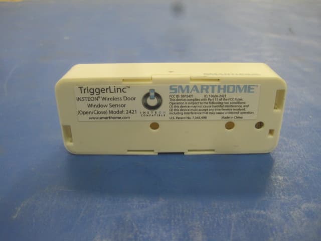
Click to zoom
Application Details
- Equipment Class
- DXT - Part 15 Low Power Transceiver, Rx Verified
- Date of Grant
- May 15, 2012
- Application Purpose
- Original Equipment
- Date of Application
- May 14, 2012
- Equipment Note
- INSTEON Wireless Window and Door Sensor
- Frequency Range
- 914.90000000 - 915.10000000
- Company
- Insteon Technologies, LLC
- Country
- United States
Documents & Files
Document Text
Text extracted from the exhibit documents filed with the FCC. Open a document above to read the original.
Users Manual
TriggerLinc INSTEON ® Wireless Door Window Sensor (Open/Close) Model : 2843-2 TriggerLinc Owner’s Manual TABLE OF CONTENTS ABOUT TRIGGERLINC................................................................................................................................ 3 Key TriggerLinc Features .......................................................................................................................... 3 What is Included with TriggerLinc ............................................................................................................. 3 WHAT IS INSTEON?.................................................................................................................................... 4 INSTALLATION ............................................................................................................................................ 5 TriggerLinc Hardware ................................................................................................................................ 5 Installing TriggerLinc ................................................................................................................................. 6 Connecting an External Sensor to TriggerLinc ......................................................................................... 6 CONTROLLING INSTEON RESPONDERS FROM TRIGGERLINC........................................................... 7 Linking TriggerLinc to an INSTEON Responder ....................................................................................... 7 Unlinking an INSTEON Responder from TriggerLinc................................................................................7 Using TriggerLinc’s Multi-Scene Mode...................................................................................................... 8 CREATING INSTEON SCENES .................................................................................................................. 9 ADVANCED FEATURES ............................................................................................................................. 9 Advanced Use of External Sensors with TriggerLinc ................................................................................ 9 Restoring Power to TriggerLinc ................................................................................................................. 9 Resetting TriggerLinc to its Factory Default Settings .............................................................................. 10 ABOUT INSTEON ...................................................................................................................................... 10 Using Dual-Band INSTEON Devices to Upgrade Your Network............................................................. 10 Important Note about INSTEON Networks; Split Single-Phase vs. 3-Phase Installation ....................... 10 Further Enhancing Reliability .................................................................................................................. 11 ADDITIONAL RESOURCES ...................................................................................................................... 11 SPECIFICATIONS, CERTIFICATION, AND WARRANTY ........................................................................ 11 Specifications .......................................................................................................................................... 11 FCC & Industry Canada Compliance Statement.....................................................................................11 Limited Warranty ..................................................................................................................................... 12 TriggerLinc Owner’s Manual Page 3 of 12 ABOUT TRIGGERLINC TriggerLinc can wirelessly control lights or appliances throughout your home. Program any INSTEON device to react when the magnetic contact is broken and re-established on TriggerLinc. Useful for doors, windows, drawers, cabinets, or anything else that opens. You can optionally connect an external contact closure sensor of any type (e.g., hidden contacts or doorbell button). Key TriggerLinc Features Installs and Links to other INSTEON devices in minutes Operates via radio frequency (RF) to eliminate unsightly and inconvenient wiring Battery-operated for easy installation Wires standard security sensors to TriggerLinc to monitor several doors or windows Excellent range – up to 150 feet from the nearest access point Indicates INSTEON setup mode activity and operational states with a Status LED Stores setup state in memory so settings aren’t lost when batteries are removed Two-year warranty What is Included with TriggerLinc TriggerLinc – INSTEON Wireless Door Window Sensor (Open/Close) Magnet One (1) AA battery Quick-Start Guide Status LED Main case Magnet Indicator arrows TriggerLinc Owner’s Manual Page 4 of 12 WHAT IS INSTEON? Since its inception in 2005, INSTEON has become a best-selling home-control networking technology, offering more reliability and flexibility than any other home management system on the market. INSTEON systems are simple, reliable, and affordable. Simple, because each device takes mere minutes to install. Reliable, because every INSTEON device works as a network repeater, ensuring your commands will not be lost. Affordable, because INSTEON can be integrated into any number of devices easily and at a very low cost. An INSTEON home grows in value with each added INSTEON device, making life more convenient, safe, and fun. How Does INSTEON Work? What makes INSTEON the most reliable home automation network is its dual-mesh network. INSTEON devices use both radio frequency (RF) signals and the home’s existing wiring to talk to each other. In an INSTEON network, every INSTEON device also acts as a repeater, receiving and sending every message to all other devices in the network. So by integrating…
Text truncated - open the document above for the full version.
ID Label/Location Info
April 18, 2012 Subject: Unit Label Location TriggerLinc - INSTEON® Wireless Window and Door Sensor #2843-2 TriggerLinc - INSTEON® Wireless Window and Door Sensor #2843-3 FCC ID: SBP28432 IC: 5202A-28432 Unit Label Location
ID Label/Location Info
April 3, 2012 Subject: Unit Label TriggerLinc - INSTEON® Wireless Window and Door Sensor #2843-2 TriggerLinc - INSTEON® Wireless Window and Door Sensor #2843-3 FCC ID: SBP28432 IC: 5202A-28432 Unit Label
Test Report
This report contains a total of 26 pages and may be reproduced in full only. Partial reproduction may only be done with the written consent of CKC Laboratories, Inc. SmartLabs, Inc. TEST REPORT FOR TriggerLinc - INSTEON Window and Door Sensor, 2843-2 Tested To The Following Standards: FCC Part 15 Subpart C Sections 15.249 and RSS 210 Issue 8 Report No.: 92578-10 Date of issue: March 2, 2012 This test report bears the accreditation symbol indicating that the testing performed herein meets the test and reporting requirements of ISO/IEC 17025 under the applicable scope of EMC testing for CKC Laboratories, Inc. We strive to create long-term, trust based relationships by providing sound, adaptive, customer first testing services. We embrace each of our customers’ unique EMC challenges, not as an interruption to set processes, but rather as the reason we are in business. Page 2 of 26 Report No.: 92578-10 TABLE OF CONTENTS Admi ni s trati ve Informati on............................................................................................................................................................ 3 Tes t R eport Informati on............................................................................................................................................................. 3 Report Authori zati on .................................................................................................................................................................. 3 Tes t Facili ty Informati on............................................................................................................................................................. 4 Si te Regi s trati on & Accredi tati on Informati on....................................................................................................................... 4 Summary of R es ul ts .................................................................................................................................................................... 5 Condi ti ons Duri ng Tes ti ng .......................................................................................................................................................... 5 Equipment Und er Tes t................................................................................................................................................................ 6 Peri pheral Devi ces ....................................................................................................................................................................... 6 FCC Part 15 Subpart C ..................................................................................................................................................................... 7 15.31(e) Vol tage Vari ati ons ....................................................................................................................................................... 7 15.249(a)(b) RF Power Output .................................................................................................................................................. 9 -20dBc Occupi ed Bandwi dth ...................................................................................................................................................11 Bandedge ....................................................................................................................................................................................13 15.249(d) Radiated Spuri ous Emissi ons ................................................................................................................................18 RSS-210 ............................................................................................................................................................................................22 99 % Bandwi dth .........................................................................................................................................................................22 Suppl emen tal Informati on ...........................................................................................................................................................25 Meas uremen t Unc ertai nty ......................................................................................................................................................25 Emi ssi ons Tes t Detai ls...............................................................................................................................................................25 Page 3 of 26 Report No.: 92578-10 ADMINISTRATIVE INFORMATION Test Report Information REPORT PREPARED FOR: REPORT PREPARED BY: SmartLabs, Inc. 16542 Mi l l ikan Ave. Irvi ne, CA 92606 Di anne Dudl ey CKC Laboratori es , Inc. 5046 Si erra Pi nes Dri ve Mari pos a, CA 95338 Repres entati ve: Matthew Meyer Proj ect Number: 92578 Cus tomer Reference Number: 12-3MM0126-01 DATE OF EQUIPMENT RECEIPT: February 16, 2012 DATE(S) OF TESTING: February 16-21, 2012 Report Authorization The tes t data contai ned i n thi s report documents the obs erved tes ti ng parameters pertai ni ng to and are rel evant for onl y the s ampl e equi pment tes ted i n the agreed upon operati onal mode(s ) and confi gurati on(s ) as i denti fi ed herei n. Compl i ance as s es s ment remai ns the client’s responsibility. Thi s report may not be us ed to cl ai m product endors ement by A2LA or any government agenci es . Thi s tes t report has been authori zed for rel eas e under qual i ty control from CKC Laboratori es , Inc. Steve Behm Director of Quality Assurance & Engineering Services CKC Laboratories, Inc. Page 4 of 26 Report No.: 92578-10 Test Facility Information Our l aboratori es are confi gured to effecti vel y tes t a wi de vari ety of product types . CKC uti l i zes fi rs t cl as s tes t equi pment, anechoi c chambers , data acqui s i ti on and i nformati o…
Text truncated - open the document above for the full version.
Contact Information
Applicant
John Lockyer(Suite 105-665)
Technical Contact
SmartLabs, Inc.Matt Meyer
[email protected]949-221-0037
16542 Millikan Ave · Irvine, California · United States
Test Firm
CKC Laboratories, Inc.Steve Behm
Technical Specifications
| # | Rule Parts | Frequency Range | Power Output |
|---|---|---|---|
| 1 | 15C | 914.9 MHz - 915.1 MHz | - |
Other Applications from Insteon Technologies, LLC

SBP-MS01
Nov 28, 2020Multi Sensor
Equipment Class
DXX - Part 15 Low Power Communication Device Transmitter
SBP-BC01
Sep 10, 2020Bridge Controller
Equipment Class
DSS - Part 15 Spread Spectrum Transmitter
SBP-WR01
Mar 21, 2020Smart Outlet
Equipment Class
DXX - Part 15 Low Power Communication Device Transmitter
SBP-WALL
Mar 19, 2020Smart Wall Switch
Equipment Class
DXX - Part 15 Low Power Communication Device Transmitter
SBP26632
Sep 30, 2014On/Off Outlet
Equipment Class
DXT - Part 15 Low Power Transceiver, Rx Verified