SG70512C1000CDMA 2000 1X Mobile Phone
Haier Telecom (Qingdao) Co., Ltd.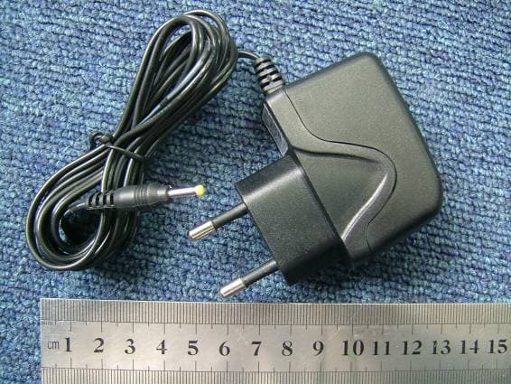
Click to zoom
Application Details
- Equipment Class
- TNE - Licensed Non-Broadcast Transmitter Held to Ear
- Date of Grant
- Feb 07, 2006
- Application Purpose
- Original Equipment
- Date of Application
- Feb 07, 2006
- Equipment Note
- CDMA 2000 1X Mobile Phone
- Frequency Range
- 825.25000000 - 847.75000000
- Country
- China
Documents & Files
Document Text
Text extracted from the exhibit documents filed with the FCC. Open a document above to read the original.
Users Manual
Error! No index entries found. C1000 USER GUIDE i _______________________________________ Trademark Statement: “‘HaierC1000’, ‘iPAS’, and the HaierC1000 logo are trademarks of HaierC1000, Inc.” Copyright Statement: “©HaierC1000, Inc. 2005. All rights reserved. No part of this publication may be reproduced in any form or by any means without the prior written permission of HaierC1000, Inc.” Warranty Language: “The contents of this manual, whether in whole or in part, do not constitute any express or implied warranty with respect to any products of HaierC1000, Inc., or its subsidiaries.” ii Table of Contents SAFETY PRECAUTIONS.................................................... 1 SAFETY NOTES................................................................................... 1 NOTICE............................................................................................... 1 SAR INFORMATION.............................................................................. 2 PERSONAL.......................................................................................... 2 MOBILE PHONE................................................................................... 3 BATT ERY............................................................................................. 3 ON THE ROAD..................................................................................... 4 ON AN AIRPLANE................................................................................. 4 1. GETTING STARTED....................................................... 5 1.1 BATTERY....................................................................................... 5 1.1.1 Removing and installing the battery.................................................6 1.1.2 Charging the battery........................................................................6 1.1.3 Using the battery..............................................................................7 1.1.4 Battery charge level.........................................................................7 1.2 CONNECTING TO THE NETWORK..................................................... 7 1.2.1 UIM card..........................................................................................7 1.2.2 Inserting the UIM card......................................................................8 1.2.3 Unlocking the UIM...........................................................................9 1.2.4 Connecting to the network.............................................................10 1.3 STANDBY SCREEN AND CONTENT.................................................. 10 1.4 BUTTON FUNCTIONS.................................................................... 11 1.5 FIGURE AND CHARACTER INPUT.................................................... 13 1.6 PHONE LOCK............................................................................... 13 1.7 INPUT METHOD............................................................................ 14 1.7.1 Editing window...............................................................................14 1.7.2 Switch between input methods......................................................14 1.7.3 Digit input method..........................................................................15 1.7.4 ABC input method..........................................................................15 1.7.5 abc input method...........................................................................15 1.7.6 Smart ABC input method...............................................................15 1.7.7 Smart abc input method.................................................................16 iii 2. DIALING AND ANSWERING........................................ 17 2.1 POWER ON/OFF.......................................................................... 17 2.2 DIALING...................................................................................... 17 2.2.1 Dialing directly...............................................................................17 2.2.2 Dialing from the phone book..........................................................18 2.2.3 Dialing by location..........................................................................19 2.3 ANSWERING A CALL...................................................................... 19 2.4 IN-CALL OPTIONS......................................................................... 19 2.4.1 Making a call to a telephone extension..........................................20 2.4.2 Adjusting the volume......................................................................20 2.4.3 Option............................................................................................20 2.4.4 Hanging up....................................................................................21 2.4.5 New SMS.......................................................................................21 2.4.6 Answering an incoming call while in-call........................................21 2.4.7 Making a new call while in-call.......................................................21 2.4.8 Call meeting...................................................................................21 3. MENU OPERATION...................................................... 22 3.1 MENU STRUCTURE....................................................................... 22 3.2 MENU OPERATION........................................................................ 22 3.3 OTHER OPERATION...................................................................... 22 3.4 MENU FUNCTION LIST.................................................................. 23 4. CONTACTS................................................................... 26 4.1 SEARCH...................................................................................... 26 4.2 ADD............................................................................................ 26 4.3 GROUP LIST..........................…
Text truncated - open the document above for the full version.
Cover Letter(s)
Federal Communications Commission Authorization and Evaluation Division Equipment Authorization Branch 7435 Oakland Mills Road, Columbia, MD 21046, U.S.A. Subject: Authorization Letter FCC ID: SG70512C1000 Applicant: Qingdao Haier Telecom Co., LTD Model: C1000 Part 22 Certification To whom it may concern: We, the undersigned, hereby authorized M o r la b. to act on our behalf in all manners relating to application for equipment authorization, including signing of all documents relating to these manners. Any and all acts carried out by SIEMIC INC., on our behalf shall have the same effect as acts of our own. This authorization is va lid until Feb. 31, 2006. Sincerely Yours, Qingdao Telecom Co. Ltd. No. 1 Haier Road, Hi-tech Zone, Qingdao, 266101, PR China Tel. No. : +86 (532) 893 9618; Fax No.: +86 (532) 893 9727 http://mobile .haier.com Type Approval M anager Qingdao Haier Telecom Co. Ltd Date:Dec 25, 2005 Eddie Wang
Cover Letter(s)
Federal Communications Commission Authorization and Evaluation Division Equipment Authorization Branch 7435 Oakland Mills Road, Columbia, MD 21046, U.S.A. Subject: Request for Confidentiality FCC ID: SG70512C1000 Applicant: Qingdao Haier Telecom Co., LTD Model: C1000 Part 22 Certification Gentlemen: In accordance with 0.459 of CFR 47, Qingdao Haier Telecom Co., LTD hereby requests confidentiality of the Block Diagrams attachment, Schematic Diagrams attachment, Operational Description attachment, and Part List/Tune-Up Procedure attachment for the above-referenced Certification application. These documents contain detailed system and equipment description and related information about the product which Haier considers to be proprietary, confidential, and a custom design and, otherwise, would not release to the general public. Since this design is a basis from which future technological products will evolve, Haier feels this information would be of benefit to its competitors, and that the disclosure of the information in these documents would give our competitors an unfair advantage in the market. Sincerely Yours, Qingdao Telecom Co. Ltd. No. 1 Haier Road, Hi-tech Zone, Qingdao, 266101, PR China Tel. No. : +86 (532) 8893 9618; Fax No.: +86 (532) 8893 9585 http://mobile .haier.com Type Approval M anager Qingdao Haier Telecom Co. Ltd Date:Dec 25, 2005 Eddie Wang
External Photos
External Photos 1. Front View of EUT 2. Back View of EUT 3. Bottom View of EUT 4. AC adapter
ID Label/Location Info
Label Label Location
Internal Photos
Internal Photos
RF Exposure Info
No. SAR06-002 Page 3 of 47 Contents 1. GENERAL CONDITIONS 2. ADMINISTRATIVE DATA 2.1. Identification of the Responsible Testing Laboratory 2.2. Identification of the Responsible Testing Location(s) 2.3. Organization Item 2.4. Identification of Applicant 2.5. Identification of Manufacture 3. EQUIPMENT UNDER TEST (EUT) 3.1. Identification of the Equipment under Test 3.2. Identification of all used Test Sample of the Equipment under Test 4. OPERATIONAL CONDITIONS DURING TEST 4.1. Schematic Test Configuration 4.2. SAR Measurement System 5. CHARACTERISTICS OF THE TEST 5.1. Applicable Limit Regulations 5.2. Applicable Measurement Standards 6. LABORATORY ENVIRONMENT 7. TEST RESULTS 7.1. Dielectric Performance 7.2. Summary of Measurement Results 7.3. Conclusion 8. MEASUREMENT UNCERTAINTY 9. MAIN TEST INSTRUMENTS This Test Report consists of the following Annexes: Annex A: Accreditation Certificate Annex B: Test Layout Annex C: Sample Photographs Annex D: Graph Test Results No. SAR06-002 Page 4 of 47 1GENERAL CONDITIONS 1.1 This report only refers to the item that has undergone the test. 1.2 This report standalone dose not constitute or imply by its own an approval of the product by the certification Bodies or competent Authorities. 1.3 This document is only valid if complete; no partial reproduction can be made without written approval of Shenzhen Electronic Product Quality Testing Center. 1.4 This report cannot be used partially or in full for publicity and/or promotional purposes without previous written approval of Shenzhen Electronic Product Quality Testing Center and the Accreditation Bodies, if it applies. No. SAR06-002 Page 5 of 47 2. Administrative Date 2.1. Identification of the Responsible Testing Laboratory Company Name: ShenZhen Electronic Product Quality Testing Center Department: Testing Department Address: Electronic Testing Building, ShaHe Road, NanShan District, ShenZhen, P. R. China Telephone: +86-755-26628676 Fax: +86-755-26627238 Responsible Test Lab Managers: Mr. Wang Keqin 2.2. Identification of the Responsible Testing Location(s) Company Name: ShenZhen Electronic Product Quality Testing Center Address: Electronic Testing Building, ShaHe Road, NanShan District, ShenZhen, P. R. China 2.3. Organization Item S.E.T Report No.: SAR06_002 S.E.T Project Leader: Mr. Li Sixiong S.E.T Responsible for accreditation scope: Mr. Wang Keqin Start of Testing: 2005-12-28 End of Testing: 2006-1-10 2.4. Identification of Applicant Company Name: Qingdao Haier Telecom Co.Ltd Address: No.1,Haier Road, Qingdao 266101P.R.China Contact person: Xu jun Telephone: 86-13608968228 Fax: 86-532-88939585 2.5. Identification of Manufacture Company Name: Qingdao Haier Telecom Co.Ltd Address: No.1,Haier Road, Qingdao 266101P.R.China Contact person: Xu jun Telephone: 86-13608968228 Fax: 86-532-88939585 Notes: This data is based on the information by the applicant. No. SAR06-002 Page 6 of 47 3. Equipment Under Test (EUT) 3.1. Identification of the Equipment under Test Brand Name: Haier Type Name: C1000 Marking Name: C1000 Test frequency CDMA 800MHz Battery type H11052 Battery specification 720mAh 3.7V Antenna specification Build inside Operation mode Call established Modulation mode CDMA General description: Max. Power(EIRP) 0.443w(26.46dBm) 3.2. Identification of all used Test Sample of the Equipment under Test EUT Code ESN Hardware Version Software Version MIN 50010C01 0524008A P1 R01.03 000000000005514 No. SAR06-002 Page 7 of 47 4 OPERATIONAL CONDITIONS DURING TEST 4.1 Schematic Test Configuration During SAR test, EUT is in Traffic Mode (Channel Allocated) at Normal Voltage Condition. A communication link is set up with a System Simulator (SS) by air link, and a call is established. The TCH is allocated to 9, 384 and 758 respectively in the case of CDMA 800 MHz. The EUT is commanded to operate at maximum transmitting power. The EUT shall use its internal transmitter. The antenna(s), battery and accessories shall be those specified by the manufacturer. The EUT battery must be fully charged and checked periodically during the test to ascertain uniform power output. If a wireless link is used, the antenna connected to the output of the base station simulator shall be placed at least 50 cm away from the handset. The signal transmitted by the simulator to the antenna feeding point shall be lower than the output power level of the handset by at least 35 dB. 4.2 SAR Measurement System The SAR measurement system being used is the IndexSAR SARA2 system, which consists of a Figure1. SAR Lab Test Measurement Set-up Mitsubishi RV-E2 6-axis robot arm and controller, IndexSAR probe and amplifier and SAM phantom No. SAR06-002 Page 8 of 47 Head Shape. The system is controlled remotely from a PC, which contains the software to control the robot and data acquisition equipment. The software also displays the data obtained from test scans, and determine the averaged SAR values (averaging region 1 gram or 10 gram) for compliance testing. The measurements are done by two scan: first a coarse scan (2-Division) determines the region of the maximum SAR, afterwards the averaged SAR is measured in a second san within the shape of a cube. The measurement time takes about 20 minutes. 4.2.1 Robot system specification The robot is used to articulate the probe to programmed positions inside the phantom head to obtain the SAR readings from the DUT. 4.2.2 Probe and amplifier specification IXP-050 Indexsar isotropic immersible SAR probe The probes are constructed using three orthogonal dipole sensors arranged on an interlocking, triangular prism core. The probes have built-in shielding against static charges and are contained within a PEEK No. SAR06-002 Page 9 of 47 cylindrical enclosure material at the tip (showed in figure 2). The system uses diode compression potential (DCP) to determine SAR values for different types of modulation. Crest factor is not used for determining SAR values. The DCP for different types of modulation is determined…
Text truncated - open the document above for the full version.
Test Report
Report No. FCC06-8006 Page 2 of 41 Table of Contents 1 Test Report Certification ...............................................................................................................4 2 General Information ......................................................................................................................5 2.1 Description of EUT ...............................................................................................................5 2.2 Objective ...............................................................................................................................6 2.3 Test Standards and Results ....................................................................................................6 2.4 List of Equipments Used .......................................................................................................7 2.5 Test Facility ...........................................................................................................................7 2.6 Environmental conditions .....................................................................................................7 3 Conducted Emission Measurement...............................................................................................8 3.1 Limits of Conducted Emission..............................................................................................8 3.2 Test Procedure .......................................................................................................................8 3.3 Test Setup ..............................................................................................................................9 3.4 EUT Setup and Operating Conditions...................................................................................9 3.5 Test Results ...........................................................................................................................9 4 Radiated Emission Test ............................................................................................................... 11 4.1 Limits of Radiated Emission ............................................................................................... 11 4.2 Test Procedure ..................................................................................................................... 11 4.3 Test Setup ............................................................................................................................12 4.4 EUT Setup and Operating Conditions.................................................................................12 4.5 Test Results .........................................................................................................................12 5 Frequencies .................................................................................................................................14 5.1 Frequency Blocks Available for Cellular Service ...............................................................14 5.2 Test Procedure .....................................................................................................................14 5.3 Test Setup ............................................................................................................................15 5.4 EUT Setup and Operating Conditions.................................................................................15 5.5 Test Results .........................................................................................................................16 6 Transmitter Radiated Power (ERP) Test .....................................................................................17 6.1 Limits of ERP......................................................................................................................17 Report No. FCC06-8006 Page 3 of 41 6.2 Test Procedure .....................................................................................................................17 6.3 Test Setup ............................................................................................................................17 6.4 EUT Setup and Operating Conditions.................................................................................17 6.5 Test Results .........................................................................................................................17 7 Occupied Bandwidth ...................................................................................................................18 7.1 Definition ............................................................................................................................18 7.2 Test Procedure .....................................................................................................................18 7.3 Test Setup ............................................................................................................................18 7.4 EUT Setup and Operating Conditions.................................................................................18 7.5 Test Results .........................................................................................................................19 8 Conducted Spurious Emission Test.............................................................................................21 8.1 Limits of Conducted Spurious Emission.............................................................................21 8.2 Test Procedure .....................................................................................................................21 8.3 Test Setup ............................................................................................................................21 8.4 EUT Setup and Operating Conditions.................................................................................21 8.5 Test Results ..........................................................................…
Text truncated - open the document above for the full version.
Test Setup Photos
Test Setup Photos 1. CE 2. CSE 3. RE 4. RSE
Contact Information
Applicant
David Yang(Certification Manager)
Test Firm
ShenZhen Electronic Product Quality Testing CenterXingsun Lin
Technical Specifications
| # | Rule Parts | Frequency Range | Power Output | Emission | Tolerance |
|---|---|---|---|---|---|
| 1 | 22H | 825.25 MHz - 847.75 MHz | 270.00 mW | 1M25F9W | 2.5000000000 ppm |
Other Applications from Haier Telecom (Qingdao) Co., Ltd.
SG7201511L50
Dec 07, 2015Mobile Phone
Equipment Class
DTS - Digital Transmission System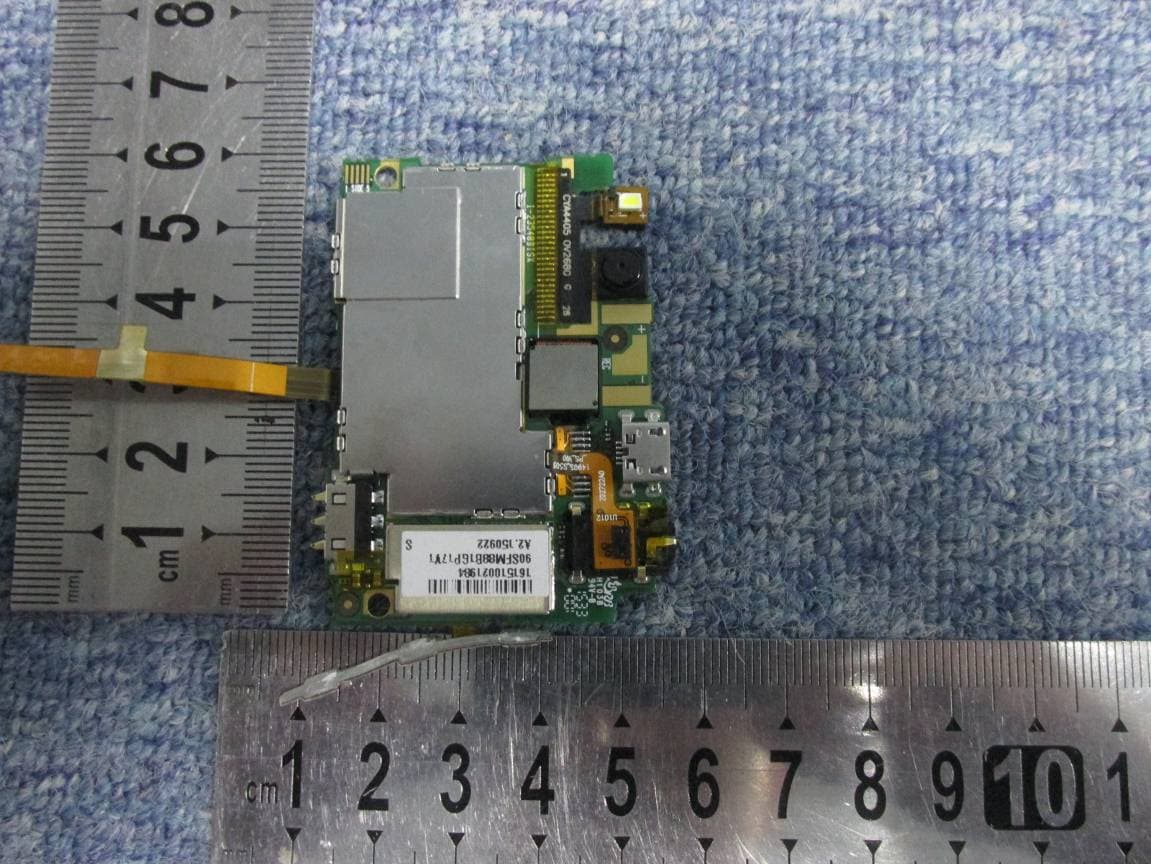
SG7201511L32
Dec 03, 2015Mobile Phone
Equipment Class
PCE - PCS Licensed Transmitter held to ear
SG71507L51
Dec 03, 2015L51
Equipment Class
DTS - Digital Transmission System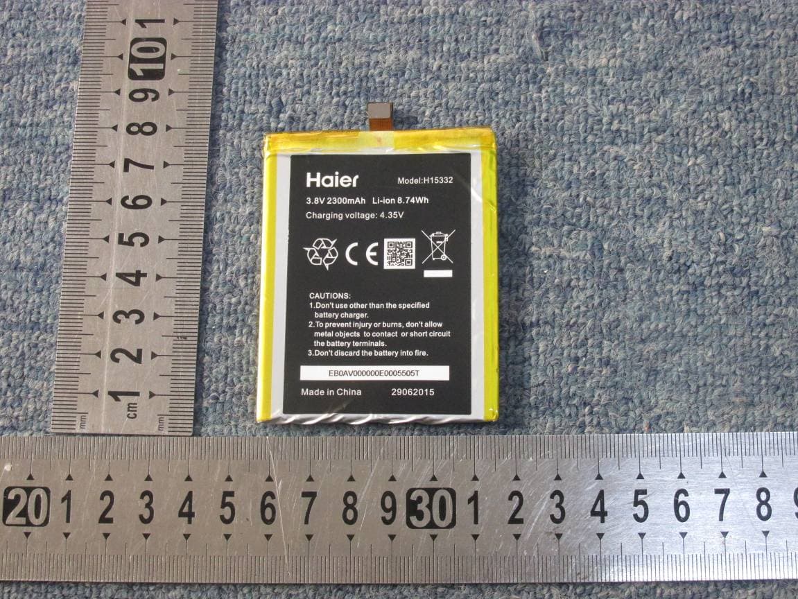
SG720151015I70
Nov 03, 2015Smart phone
Equipment Class
PCE - PCS Licensed Transmitter held to ear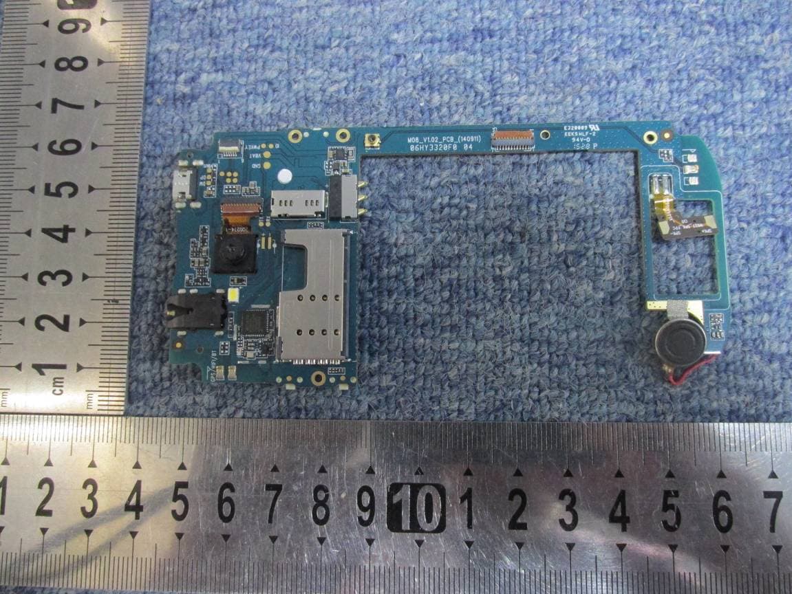
SG720151010G10
Oct 22, 2015Mobile phone
Equipment Class
DSS - Part 15 Spread Spectrum Transmitter