SG70803HC-C200MOBILE PHONE
Haier Telecom (Qingdao) Co., Ltd.
Click to zoom
Application Details
- Equipment Class
- TNE - Licensed Non-Broadcast Transmitter Held to Ear
- Date of Grant
- Apr 02, 2008
- Application Purpose
- Original Equipment
- Date of Application
- Mar 31, 2008
- Equipment Note
- MOBILE PHONE
- Frequency Range
- 825.25000000 - 847.75000000
- Country
- China
Documents & Files
Document Text
Text extracted from the exhibit documents filed with the FCC. Open a document above to read the original.
Users Manual
Welcome to use C200 mobile phone from [ Company ] Technologies Co.., Ltd. [ Company ] ® C200 CDMA Mobile Phone User Manual Copyright©2007 [ Company ] Technologies Co.., Ltd All Rights Reserved Reproduction, transfer, distribution or storage of part or all of the cont ents in this document in any form without the prior written permission as [ Company ] Technologies Co.., Ltd. Statement The contents of this manual maybe different wi th the cell phone please according the cell phone. [ Company ] reserves the right to revi se this document or withdraw it at any time without prior notice. Safety Precautions Please read these simple guidelines. Not following them may be dangerous or illegal. For further information, see the secti on of “Warnings and Precautions”. Do not switch the phone on when Mobile Phone use is prohibited or when it may cause interference or danger. Do not place your phone and its accessories in containers with strong electromagnetic field. Obey all local laws. Always keep your hands free to operate the vehicle while driving. Your first consideration while driving should be road safety. Hospitals or health care facilities may be using equipment that could be sensitive to external radio frequency energy. Follow any regulations or rules in force. Do not use the phone at a refueling point. Do not use near fuel or chemicals. Follow any restrictions. Wireless devices can cause interference in aircraft. Keep the phone and all its parts, includi ng accessories, out of the reach of small children. Use only approved batteries and charger s. Disconnect the charger from the power source when it is not in use. Do not leave the battery connected to a charger for more than a week, since overcharging may shorten its lift. Only qualified personnel should service the phone or install the phone in a vehicle. Faulty installation or service may be dangerous and may invalidate any warranty applicable to the device. i Contents 1 Getting to Know Your Phone..................................................................................... 1 Packing list ................................................................................................................... ... 1 Basic specif ication ........................................................................................................... 1 Mobile phon e appear ance ............................................................................................... 2 2 Getting Started............................................................................................................ 7 Install and char ge the p hone ........................................................................................... 7 3 Basic Functions ........................................................................................................... 8 Switching On/Off.............................................................................................................. 8 Making pho ne ca ll............................................................................................................ 8 Answering the ca ll.......................................................................................................... 10 Operations dur ing a call................................................................................................. 11 Keypad lock ................................................................................................................... 11 4 Text Entry.................................................................................................................. 12 Text input method .......................................................................................................... 12 ii Change the in put method .............................................................................................. 13 5 Contacts..................................................................................................................... 14 Add ne w........................................................................................................................ . 14 List ........................................................................................................................... ...... 15 Search ......................................................................................................................... .. 15 Groups ......................................................................................................................... .. 16 Multicopy ...................................................................................................................... . 17 Speed dial..................................................................................................................... . 17 Dele te ......................................................................................................................... ... 18 Storage lo cation ............................................................................................................. 18 Memory stat us ............................................................................................................... 19 My number..................................................................................................................... 19 6 Messages .................................................................................................................... 20 Text mess age (SMS ) ..................................................................................................... 20 Text mess age m enus ..................................................................................................... 21 Write and send SMS mess ages..................................................................................... 22 Text mess age optio ns .................................................................................................... 23 iii Templa tes ....................…
Text truncated - open the document above for the full version.
Cover Letter(s)
Date: 03/31/2008 To: Federal Communications Commission, Authorization & Evaluation Division, 7435 Oakland Mills Road, Columbia, MD 21046 To Whom It May Concern: The Haier Telecom (Qingdao) Co., Ltd. , the undersigned, hereby authorizes Mr. Wu Xuewen from Shenzhen Morlab Communications Technology Co., Ltd., to act on the behalf of the Haier Telecom (Qingdao) Co., Ltd. solely in matters relating to the application for an FCC equipment authorization for FCC ID # SG70803HC-C200 including the signing of documents in connection with this Application. Necessary acts carried out by Haier Telecom (Qingdao) Co., Ltd. on our behalf of the Haier Telecom (Qingdao) Co., Ltd. in connection with the Application shall have the same effect as acts of the Haier Telecom (Qingdao) Co., Ltd.. The Haier Telecom (Qingdao) Co., Ltd. also hereby certify that no party to this application is subject to a denial of benefits, including FCC benefits, pursuant to Section 5301 of the Anti-Drug Abuse Act of 1988, 21 U.S.C. 853(a). Thank you for your attention to this matter. Sincerely Yours, James Shi Type Approval Manager Haier Telecom (Qingdao) Co., Ltd.
Cover Letter(s)
Date: 03/31/2008 To: Federal Communications Commission, Authorization & Evaluation Division, 7435 Oakland Mills Road, Columbia, MD 21046 Re: Haier Telecom (Qingdao) Co., Ltd. FCC ID: SG70803HC-C200 FCC Part 22H Certification Confidentiality Request Gentlemen: This letter is to comply with 47 CFR 0.457 and 0.459 pertaining to confidentiality material. Haier Telecom (Qingdao) Co., Ltd. requests that the following documents regarding this submission for FCC ID: SG70803HC-C200 be kept confidential: Exhibit Type File Name Block Diagram Block Diagram.pdf Schematics Circuit Diagram.pdf Operational Description Operational Description.pdf Part list BOM.pdf Tune-Up-Procedure Tune up procedure.pdf Those documents contain detailed system and equipment description and related information about the product which Haier Telecom (Qingdao) Co., Ltd. considers to be confidential proprietary, a custom design and, otherwise, not releasable to the general public. Since this design is a basis form which future technological products will evolve, Haier Telecom (Qingdao) Co., Ltd. considers this information would be of benefit to its competitors, and that the disclosure of the information in these documents would give competitors an unfair advantage in the market. James Shi Type Approval Manager Haier Telecom (Qingdao) Co., Ltd.
Cover Letter(s)
TIMCO ENGINEERING INC From: Bruno Clavier [[email protected]] Sent: Tuesday, April 01, 2008 10:38 AM To: Randa Kotait Subject: FW: TIMCO-TCB/Request for additional info - HAIER TELECOM (QINGDAO) CO., LTD. - FCC ID: SG70803HC-C200 Randa, Please pdf this reply and mark the 731 Form, so Alexis will know that this reply must be uploaded with this filing. Regards, Bruno -----Original Message----- From: xuewen.wu [mailto:[email protected]] Sent: Tuesday, April 01, 2008 12:23 AM To: 'TEI' Cc: 'Bruno Clavier'; 'Timco - Gilbert Lui' Subject: RE: TIMCO-TCB/Request for additional info - HAIER TELECOM (QINGDAO) CO., LTD. - FCC ID: SG70803HC-C200 SUBJECT: HAIER TELECOM (QINGDAO) CO., LTD. - FCC ID: SG70803HC-C200 REFERENCE: JOB 631CC8 Dear Bruno, Thanks for your mail very much. Please review my answer below: 1. BLOCK DIAGRAM: resubmit, you will find the resubmit documents. 2. It is not available for end-user to connect mobile phone to computer. It is not a Class B computer. 3. Revised and resubmitted. Best Regards! Xuewen Wu MORLAB :::CCCCEFCCRoHSGCFULOTATELECBluetooth::: Shenzhen Morlab Communications Technology Co., Ltd. Electronic Testing Building, Shahe Road, Xili, Nanshan District, Shenzhen, Guangdong Province, P. R. China 518055 Phone: +86 0755 8613 0298-3011 Mobile: +86 (0) 13352901006 Fax: +86 0755 8613 0218 Email: [email protected] file:///X|/H/HAIER_SG7/631CC8/CUSTOMER%20CORRESPONDANCE.htm (1 of 3)4/1/2008 2:29:03 PM TIMCO ENGINEERING INC http://www.morlab.cn From: Bruno Clavier [mailto:[email protected]] Sent: Tuesday, April 01, 2008 3:31 AM To: [email protected] Cc: Gilbert Lui Subject: TIMCO-TCB/Request for additional info - HAIER TELECOM (QINGDAO) CO., LTD. - FCC ID: SG70803HC-C200 Importance: High TIMCO ENGINEERING INC. TCB & FCB 849 NW State Road 45 FCC Approvals Newberry, Florida 32669 Industry Canada Approvals http://www.timcoengr.com Notified Body for Europe 888.472.2424 F 352.472.2030 email: [email protected] 3/31/2008 MR. WU XUEWEN SHENZHEN MORLAB COMMUNICATIONS TECHNOLOGY CO., LTD. +86-755-86120268 +86-755-86120218 [email protected]; [email protected] SUBJECT: HAIER TELECOM (QINGDAO) CO., LTD. - FCC ID: SG70803HC-C200 REFERENCE: JOB 631CC8 Dear MR. XUEWEN: This application is on hold until these questions are resolved. Please answer all question(s) together and only respond to [email protected]. Any other method will cause unnecessary delay. DO NOT HIT REPLY! Your response should be sent ONLY to [email protected]. Any additional exhibits that are sent should be UPLOADED at our web site – please do not attach files to your email. Responses should also contain the job number, applicant name and FCC ID of the device. If an acceptable response is not received within 2 weeks the job will be closed & there will be additional charges to reopen. Answer all questions. Be sure to number or identify your answer with the corresponding file:///X|/H/HAIER_SG7/631CC8/CUSTOMER%20CORRESPONDANCE.htm (2 of 3)4/1/2008 2:29:03 PM TIMCO ENGINEERING INC question. If you are referring to another document, be sure to give the page number and paragraph reference where your response can be found. Based upon our review of this application we have the following questions: 1. BLOCK DIAGRAM: Please provide us with a Block Diagram that is easily read. The Block Diagram we received is blurry and unreadable even when “zoomed in” on. 2. Please explain whether this device has provisions for connection to a class B personal computer. If it can connect to a class B personal computer, the computer peripheral portion of this product is subject to the Declaration of Conformity (DoC) or Certification procedure. Please provide EITHER: A) An attestation from the Grantee stating that the “Declaration of conformity procedure will be applied” OR B) A 731 form (JBP equipment class) along with a part 15 subpart B test report and exhibits required under 2.1033(b). 3. Operational/circuit description (tune-up procedure): The power listed for this device is 22.8dBm +/-0.2dB, whereas the maximum measured conducted output power is 27.33dBm. The measured conducted power should not exceed the tune-up power level. Please explain or revise accordingly. Sincerely, Bruno Clavier Timco Engineering, Inc. __________ NOD32 2988 (20080331) ÐÅÏ¢ __________ Õâ ̧öÏûÏ¢ÒѾ-Í ̈¹ýÁË NOD32 ·À¶¾Ïμͳμļì²â. http://www.eset.com file:///X|/H/HAIER_SG7/631CC8/CUSTOMER%20CORRESPONDANCE.htm (3 of 3)4/1/2008 2:29:03 PM
External Photos
External Photos 1. Front View of EUT 2. Back View of EUT 3. Side View of EUT
ID Label/Location Info
Label Label Location
ID Label/Location Info
Date: 03/31/2008 Equipment Authorization Division Office of Engineering and Technology Federal Communications Commission 7435 Oakland Mills Road Columbia, MD 21046 Ref: FCC ID: SG70803HC-C200 Dear Sirs: Haier Telecom (Qingdao) Co., Ltd. requests acceptance of the labeling proposal described below for cell phone bearing FCC identifier SG70803HC-C200. The subject cell phone are compact handheld models as shown in figure 1, authorized under 47CFR Part 22 Subpart H for CDMA mobile services. Figure 1. Because the majority of the cell phone housing is composed of display, speaker, operating controls, camera and a removable battery pack, there is extremely limited space available to attach the required label carrying the FCC identifier. Attaching the label to the battery pack is not acceptable because the battery pack is a removable item. For this reason, Haier Telecom proposes placing the label carrying the FCC identifier inside the battery compartment as shown in figure 2. Figure 2. The consumer packaging for these models includes the battery pack as a separate item, NOT installed on the radio. As such, the FCC identifier will be readily visible to the user before the battery pack is installed and whenever the battery pack is removed or replaced. In this location, the label will also be protected from physical abuse and remain readable for the anticipated life of the device. The consumer packaging for these models is a "gift box" which does not allow the transceiver to be seen at time of purchase. In order to meet the requirements of 47CFR Part 2.925 (d), Haier Telecom will add the FCC identifier " SG70803HC-C200" to the outside of the consumer "gift box" packaging. Thank you for your attention to this matter. James Shi Type Approval Manager Haier Telecom (Qingdao) Co., Ltd.
Internal Photos
Internal Photos
RF Exposure Info
IMMERSIBLE SAR PROBE CALIBRATION REPORT Part Number: IXP – 050 S/N 0201 June 2007 Indexsar Limited Oakfield House Cudworth Lane Newdigate Surrey RH5 5BG Tel: +44 (0) 1306 632 870 Fax: +44 (0) 1306 631 834 e-mail: [email protected] Page 1 of 19 Page 2 of 19 Oakfield House F e-ma Indexsar Limited Cudworth Lane Newdigate Surrey RH5 5BG Tel: +44 (0) 1306 632 870 ax: +44 (0) 1306 631 834 il: [email protected] Calibration Certificate 0706/0201 Dosimetric E-field Probe ype: IXP-050 T anufacturer: IndexSAR, UK M Serial Number: 0201 Place of Calibration: IndexSAR, UK IndexSAR Limited hereby declares that the IXP-050 Probe named above has been e calibrated for conformity to the IEEE 1528 and CENELEC EN 50361 standards on th date shown below. Date of Initial Calibration: 22 nd June 2007 The probe named above equire a calibration checwill rk on the date shown below. Next Calibration Date: June 2008 The calibration was carried out using the methods described in the calibration cable, the standards used in the calibration process are traceable to the Calibrated By: document. Where appli UK’s National Physical Laboratory. Approved By: Please keep this certificate with the calibration document. When the probe is sent for a calibration check, please include the calibration document. Page 3 of 19 TRODUCTION his Report presents measured calibration data for a particular Indexsar SAR dexsar probes are characterised using procedures that, where applicable, cal ach step of the calibration procedure and the equipment used is described in ALIBRATION PROCEDURE . Objectives IN T probe (S/N 0201) and describes the procedures used for characterisation and calibration. In follow the recommendations of CENELEC [1] and IEEE [2] standards. The procedures incorporate techniques for probe linearisation, isotropy assessment and determination of liquid factors (conversion factors). Calibrations are determined by comparing probe readings with analyti computations in canonical test geometries (waveguides) using normalised power inputs. E the sections below. C 1 he calibration process comprises four stages ity factors which optimise the 2) lar offset of 3) o sets of channel sensitivity factors 4) y of interest, application of these channel a tors . Probe output T 1) Determination of the channel sensitiv probe’s overall rotational isotropy in 900MHz brain fluid Determination of the channel sensitivity factors and angu the X channel which together optimise the probe’s spherical isotropy in 900MHz brain fluid Numerical combination of the tw to give both acceptable rotational isotropy and acceptable spherical isotropy values At each frequenc sensitivity factors to model the exponential decay of SAR in waveguide fluid cell, and hence derive the liquid conversion fac at that frequency 2 he probe channel output signals are linearised in the manner set out in Refs U lin = U o/p + U o/p / DCP (1) where U lin is the linearised signal, U o/p is the raw output signal in voltage units CP is determined from fitting equation (1) to measurements of U lin versus T [1] and [2]. The following equation is utilized for each channel: 2 and DCP is the diode compression potential in similar voltage units. D source feed power over the full dynamic range of the probe. The DCP is a characteristic of the Schottky diodes used as the sensors. For the IXP-050 probes with CW signals the DCP values are typically 0.10V (or 20 in the voltage units used by Indexsar software, which are V*200). Page 4 of 19 In turn, measurements of E-field are determined using the following equation (where output voltages are also in units of V*200): E liq 2 (V/m) = U linx * Air Factor x * Liq Factor x + U liny * Air Factor y * Liq Factor y + U linz * Air Factor z * Liq Factor z (3) Here, “Air Factor” represents each channel’s sensitivity, while “Liq Factor” represents the enhancement in signal level when the probe is immersed in tissue-simulant liquids at each frequency of interest. 3. Selecting channel sensitivity factors to optimise isotropic response After manufacture, the first stage of the calibration process is to balance the three channels’ Air Factor values, thereby optimising the probe’s overall axial response (“rotational isotropy”). To do this, a 900MHz waveguide containing head-fluid simulant is selected. Like all waveguides used during probe calibration, this particular waveguide contains two distinct sections: an air-filled launcher section, and a liquid cell section, separated by a dielectric matching window designed to minimise reflections at the air-liquid interface. The waveguide stands in an upright position and the liquid cell section is filled with 900MHz brain fluid to within 10 mm of the open end. The depth of liquid ensures there is negligible radiation from the waveguide open top and that the probe calibration is not influenced by reflections from nearby objects. During the measurement, a TE 01 mode is launched into the waveguide by means of an N-type-to-waveguide adapter. The probe is then lowered vertically into the liquid until the tip is exactly 10mm above the centre of the dielectric window. This particular separation ensures that the probe is operating in a part of the waveguide where boundary corrections are not necessary. Care must also be taken that the probe tip is centred while rotating. The exact power applied to the input of the waveguide during this stage of the probe calibration is immaterial since only relative values are of interest while the probe rotates. However, the power must be sufficiently above the noise floor and free from drift. The dedicated Indexsar calibration software rotates the probe in 10 degree steps about its axis, and at each position, an Indexsar ‘Fast’ amplifier samples the probe channels 500 times per second for 0.4 s. The raw U o/p data from each sample are packed into 10 bytes and transmitted back to the PC controller via an optical cable. U linx , U liny and U linz are derived from the raw U o/p values…
Text truncated - open the document above for the full version.
RF Exposure Info
No.SAR08-025 Page 3 of 56 Contents 1. GENERAL CONDITIONS 2. ADMINISTRATIVE DATA 2.1. Identification of the Responsible Testing Laboratory 2.2. Identification of the Responsible Testing Location(s) 2.3. Organization Item 2.4. Identification of Applicant 2.5. Identification of Manufacture 3. EQUIPMENT UNDER TEST (EUT) 3.1. Identification of the Equipment under Test 3.2. Identification of all used Test Sample of the Equipment under Test 4. OPERATIONAL CONDITIONS DURING TEST 4.1. Schematic Test Configuration 4.2. SAR Measurement System 5. CHARACTERISTICS OF THE TEST 5.1. Applicable Limit Regulations 5.2. Applicable Measurement Standards 6. LABORATORY ENVIRONMENT 7. 3G MEASUREMENT PROCEDURES 8. TEST RESULTS 8.1. Dielectric Performance 8.2. Summary of Measurement Results 8.3. Conclusion 9. MEASUREMENT UNCERTAINTY 10. MAIN TEST INSTRUMENTS This Test Report consists of the following Annexes: Annex A: Accreditation Certificate Annex B: Test Layout Annex C: Sample Photographs Annex D: Graph Test Results Annex E: System Performance Check Data No.SAR08-025 Page 4 of 56 1ˊGENERAL CONDITIONS 1.1 This report only refers to the item that has undergone the test. 1.2 This report standalone dose not constitute or imply by its own an approval of the product by the certification Bodies or competent Authorities. 1.3 This document is only valid if complete; no partial reproduction can be made without written approval of Shenzhen Electronic Product Quality Testing Center. 1.4 This report cannot be used partially or in full for publicity and/or promotional purposes without previous written approval of Shenzhen Electronic Product Quality Testing Center and the Accreditation Bodies, if it applies. No.SAR08-025 Page 5 of 56 2. Administrative Date 2.1. Identification of the Responsible Testing Laboratory Company Name: ShenZhen Electronic Product Quality Testing Center Department: Testing Department Address: Electronic Testing Building, ShaHe Road, NanShan District, ShenZhen, P. R. China Telephone: +86-755-26628676 Fax: +86-755-26627238 Responsible Test Lab Managers: Mr. Wu Li’an 2.2. Identification of the Responsible Testing Location(s) Company Name: ShenZhen Electronic Product Quality Testing Center Address: Electronic Testing Building, ShaHe Road, NanShan District, ShenZhen, P. R. China 2.3. Organization Item S.E.T Report No.: SAR08-025 S.E.T Project Leader: Mr. Li Sixiong S.E.T Responsible for accreditation scope: Mr. Wu Li’an Start of Testing: 2008-3-05 End of Testing: 2008-3-27 2.4. Identification of Applicant Company Name: QINGDAO HAIER TELECOM CO., LTD. Address: No.1,Haier Road,Hi-tech Zone,Qingdao,266101,P.R.China Contact person: XuJun Telephone: +86(532)88936513 Fax: +86(532)88936513 2.5. Identification of Manufacture Company Name: QINGDAO HAIER TELECOM CO., LTD. Address: No.1,Haier Road,Hi-tech Zone,Qingdao,266101,P.R.China Contact person: XuJun Telephone: +86(532)88936513 Fax: +86(532)88936513 Notes: This data is based on the information by the applicant. No.SAR08-025 Page 6 of 56 3. Equipment Under Test (EUT) 3.1. Identification of the Equipment under Test Brand Name: Haier Ty pe Na me: HC-C200 Marking Name: HC-C200 Test frequency CDMA 800MHz Development Stage Identical Prototype Accessories Charger Battery Battery type H24138 Battery specification 800 mAh 3.7V Antenna type Build inside Operation mode Call established General description: Modulation mode CDMA NOTE: 1. The EUT is a model of CDMA Mobile Station (“MS” for short in this report) operating in CDMA 800MHz band. 2. Please refer to Appendix C for the photographs of the EUT. For a more detailed features description about the EUT, please refer to User’s Manual. 3.2. Identification of all used Test Sample of the Equipment under Test EUT Code ESN Hardware Version Software Version / / SP HA200MT01 No.SAR08-025 Page 7 of 56 4 OPERATIONAL CONDITIONS DURING TEST 4.1 Schematic Test Configuration During SAR test, EUT is in Traffic Mode (Channel Allocated) at Normal Voltage Condition. A communication link is set up with a System Simulator (SS) by air link, and a call is established. The TCH is allocated to 25, 600 and 1175 respectively in the case of CDMA 800 MHz. The EUT is commanded to operate at maximum transmitting power. The EUT shall use its internal transmitter. The antenna(s), battery and accessories shall be those specified by the manufacturer. The EUT battery must be fully charged and checked periodically during the test to ascertain uniform power output. If a wireless link is used, the antenna connected to the output of the base station simulator shall be placed at least 50 cm away from the handset. The signal transmitted by the simulator to the antenna feeding point shall be lower than the output power level of the handset by at least 35 dB. 4.2 SAR Measurement System The SAR measurement system being used is the IndexSAR SARA2 system, which consists of a Figure1. SAR Lab Test Measurement Set-up Mitsubishi RV-E2 6-axis robot arm and controller, IndexSAR probe and amplifier and SAM phantom No.SAR08-025 Page 8 of 56 Head Shape. The system is controlled remotely from a PC, which contains the software to control the robot and data acquisition equipment. The software also displays the data obtained from test scans. In operation, the system first does an area (2D) scan at a fixed depth within the liquid from the inside wall of the phantom. When the maximum SAR point has been found, the system will then carry out a 3D scan centred at that point to determine volume averaged SAR level. 4.2.1 Robot system specification The robot is used to articulate the probe to programmed positions inside the phantom head to obtain the SAR readings from the DUT. 4.2.2 Probe and amplifier specification IXP-050 Indexsar isotropic immersible SAR probe The probes are constructed using three orthogonal dipole sensors arranged on an interlocking, triangular prism core. The probes have built-in shielding against static charges and are contained within a PEEK No.SAR08-025 Page 9…
Text truncated - open the document above for the full version.
Test Report
Report No.: SZ08030018E01 Page 2 of 51 TABLE OF CONTENTS 1.TEST RESULT CERTIFICATION ..........................................................................................4 2.GENERAL INFORMATION ....................................................................................................5 2.1Equipment under Test (EUT) Description ...............................................................................5 2.2Test Standards and Results ........................................................................................................6 2.3Facilities and Accreditations ......................................................................................................6 2.3.1Facilities ....................................................................................................................................6 2.3.2Test Equipments ........................................................................................................................6 2.3.3Test Environment Conditions....................................................................................................6 3.47 CFR PART 15B REQUIREMENTS ....................................................................................6 3.1General Information...................................................................................................................6 3.1.1Test Mode..................................................................................................................................6 3.1.2Test Setup ..................................................................................................................................6 3.2Conducted Emission ...................................................................................................................6 3.2.1Requirement ..............................................................................................................................6 3.2.2Test Procedure ...........................................................................................................................6 3.2.3Test Result .................................................................................................................................6 3.3Radiated Emission ......................................................................................................................6 3.3.1Requirement ..............................................................................................................................6 3.3.2Test Procedure ...........................................................................................................................6 3.3.3Test Result .................................................................................................................................6 4.47 CFR PART 2, PART 22H REQUIREMENTS ....................................................................6 4.1General Information...................................................................................................................6 4.1.1Conducted Related Tests ........................................................................…
Text truncated - open the document above for the full version.
Contact Information
Applicant
David Yang(Certification Manager)
Test Firm
Shenzhen Morlab Communications Technology Co.,LtdShu Luan
Technical Specifications
| # | Rule Parts | Frequency Range | Power Output | Emission | Tolerance |
|---|---|---|---|---|---|
| 1 | 22H | 825.25 MHz - 847.75 MHz | 340.00 mW | 1M25F9W | 0.1000000000 ppm |
Other Applications from Haier Telecom (Qingdao) Co., Ltd.
SG7201511L50
Dec 07, 2015Mobile Phone
Equipment Class
DTS - Digital Transmission System
SG7201511L32
Dec 03, 2015Mobile Phone
Equipment Class
PCE - PCS Licensed Transmitter held to ear
SG71507L51
Dec 03, 2015L51
Equipment Class
DTS - Digital Transmission System
SG720151015I70
Nov 03, 2015Smart phone
Equipment Class
PCE - PCS Licensed Transmitter held to ear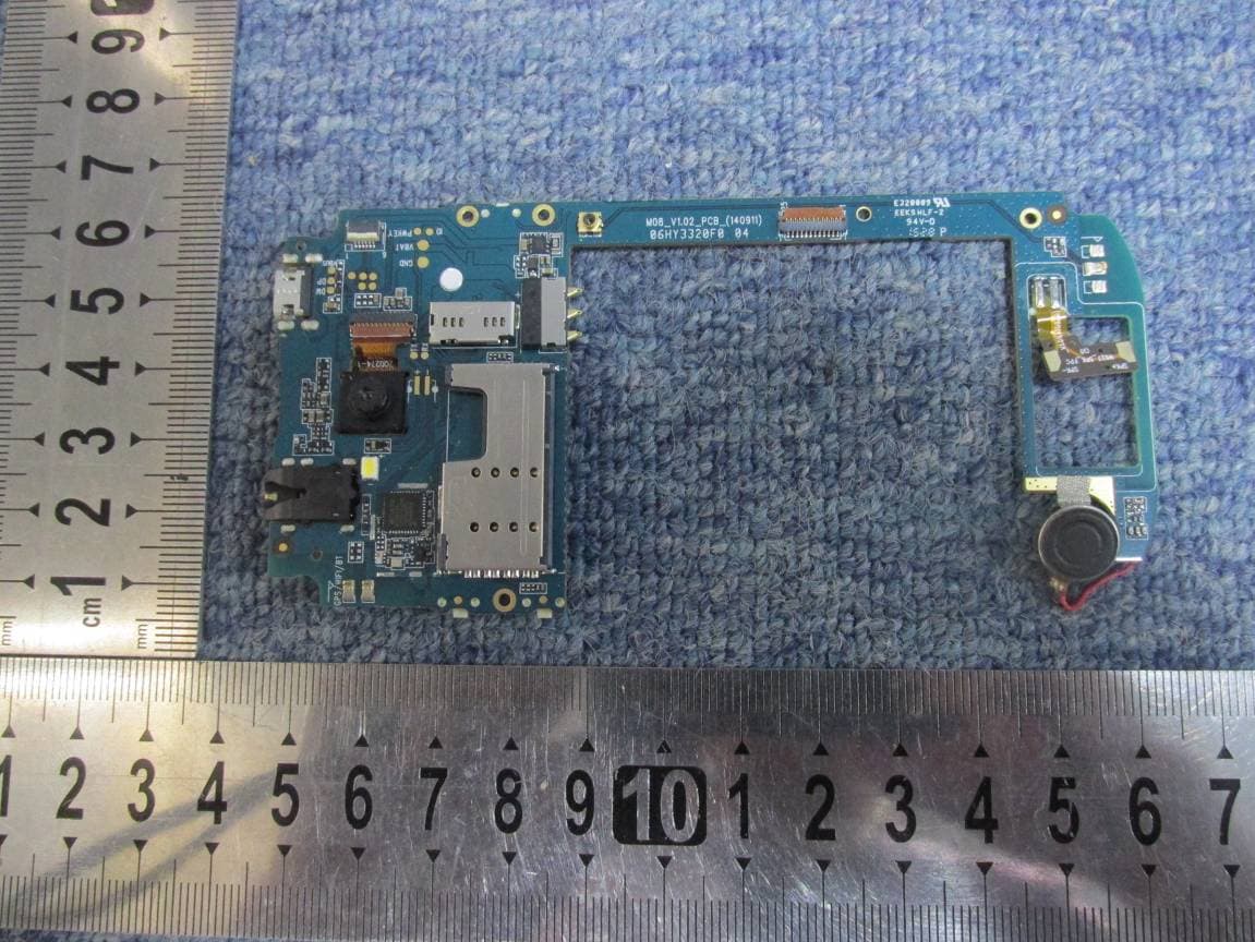
SG720151010G10
Oct 22, 2015Mobile phone
Equipment Class
DSS - Part 15 Spread Spectrum Transmitter