SG7Z3000BGSM/GPRS 1900 MHz Mobile Phone
Haier Telecom (Qingdao) Co., Ltd.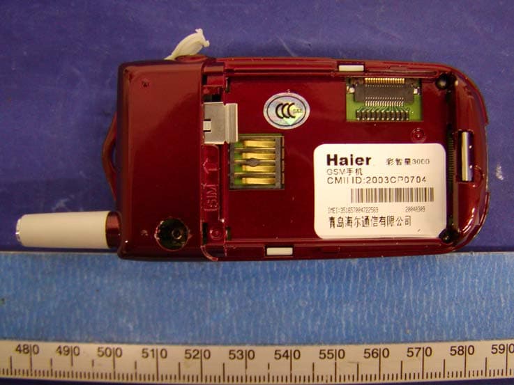
Click to zoom
Application Details
- Equipment Class
- PCE - PCS Licensed Transmitter held to ear
- Date of Grant
- Nov 01, 2004
- Application Purpose
- Original Equipment
- Date of Application
- Nov 01, 2004
- Equipment Note
- GSM/GPRS 1900 MHz Mobile Phone
- Frequency Range
- 1850.20000000 - 1909.80000000
- Country
- China
Documents & Files
Document Text
Text extracted from the exhibit documents filed with the FCC. Open a document above to read the original.
Users Manual
Haier Mobile Phone Caizhixing Z3000B Color Screen GPRS User’s Guide Notice to Users Thank you for purchasing Haier mobile phone. It blends into a unity high technology, stylish shape and versatility and is sure to add fun to your life. For safe and efficient use of your mobile phone, please read this manual carefully and keep it in a safe place for later reference. The user’s guide serves as a manual of operation instructions instead of a quality certificate. Haier reserves the power of interpretation of any misprint, discrepancy from the update, software upgrading and product improvement. Information contained herein is subject to change without notice. Compiled and printed by Qingdao Haier Telecommunication Co., Ltd. All rights reserved. Table of Contents 1. General information 1.1 Keypad 1.1.1 Number keys 1.1.2 Control keys 1.1.3 Key operation in standby mode 1.2 Display 1.3 Installing the battery 1.4 Installing the SIM card 1.5 Charging the battery 1.6 256-color cool light 2. Basic operation 2.1 Turning on the mobile phone 2.2 Turning off the mobile phone 2.3 Placing a call 2.4 Answering a call 2.5 Text input methods 2.5.1 T9 intelligent English input 2.5.2 Symbol input 2.5.3 Number input 2.6 Phonebook 2.6.1 Searching an entry 2.6.2 Creating an entry 2.6.3 Phonebook list 2.6.4 Checking the phonebook capacity 2.6.5 Deleting all entries 2.6.6 Copying all entries 2.6.7 Moving all entries 2.6.8 Group setting 2.6.9 Selecting memory 2.6.10 IP call service number 2.6.11 Personal information 2.8 Data transfer between phone and PC 2.8.1 Download MIDI ring 2.8.2 Download standby screen display 2.8.3 Transfer phone to PC 3. Menu operation 3.5 Text message (network dependent) 3.5.1 Inbox 3.5.2 Outbox 3.5.3 Composing a text message 3.5.4 Setting up the text message box 3.5.5 Deleting text messages 3.5.6 Checking the capacity 3.5.7 Voicemail 3.5.8 Text message broadcast 3.1 Call record 3.1.1 Dialed calls 3.1.2 Answered numbers 3.1.3 Missed calls 3.1.4 Deleting a call list 3.1.5 Call meters 3.3. Quick settings 3.2 Mode settings 3.2.1 Personalized settings 3.4 Phone settings 3.4.1 Ringer types 3.4.2 Volume adjustment 3.4.3 Phone settings 3.4.4 Call settings 3.4.5 Time setting 3.4.6 Security 3.4.7 Safeguard 3.4.8 Network 3.4.9 Factory setting 3.3 Call forward (network dependent) 3.5.1 Unconditional call forward 3.5.2 Call forward when busy 3.5.3 Call forward when not answered 3.5.4 Call forward when not reachable 3.5.5 Canceling call forward 3.5.6 Checking status 3.8 Advanced operations 3.8.1 Organizer 3.8.2 Alarm clock 3.8.3 Calculator 3.8.4 Stopwatch 3.8.5 Timer 3.8.6 World time 3.6.7 Biological clock 3.6 Entertainment 3.6.1 Camera 3.6.2 Game 3.6.2 Mobile QQ (network dependent) 3.6.4 Biological clock 3.7 WAP (network dependent) 3.7.1 Homepage 3.7.2 Bookmark 3.7.3 Webpage visited last time 3.7.4 Navigation 3.7.5 Settings 3.9 STK service (network dependent) 4. Accessories 4.1 Earphones 4.2 Charger 4.3 Data cable 4.4 5. Safety precautions 6. Care and maintenance 1. General information External camera / earphone jack Antenna Left softkey Volume key Left key Send key / answer Clear key Built-in speaker Up key Right softkey Enter key Right key Down key Power/End key Number keys Microphone 1.1 Keypad Your mobile phone has 25 keys and can be divided into two parts: z Number/letter keys, 12 keys in all z Control keys, 13 keys in all 1.1.1 Number/letter keys There are 12 number/letter keys, that is, 0 to 9 and the "*" key and "#" key. You can use these keys to input numbers or letters/symbols and pressing a key may correspond to different results as listed below: Editor input Letter Number Calculator Key icon Capital letter Small letter Press briefly Press and hold 1 Space Space * Conversion among input modes Conversion among input modes # Press briefly: conversion between capital and small letters Press and hold: symbol input Press briefly: conversion between capital and small letters Press and hold: symbol input 1.1.2 Control keys Power/End key Red key in the right part of the keypad. z Press to power on the phone. Press and hold during the charging process. z Press and hold to power off the phone. z Press briefly to return to the standby mode from a menu or editing mode. z Press to end a call. z Press to refuse to answer a call. Send key / Answer key Green key in the left part of the keypad. Press to place or answer a call. From standby mode, press to access dialed calls. Left softkey and right softkey The left softkey is in the upper left corner of the keypad and the right softkey is in the upper right corner of the keypad. Their functions are indicated at the bottom of the screen. Navigation Keys There are four navigation keys, namely, Right, Left, Up and Down. Up and Down: z Scroll to show the letters/symbols available for selection in the editor. z Scroll to view menus and lists. z Scroll to read messages or other texts. Note: The Up/Down keys feature auto repeat. When pressing and holding either one of these two keys, it acts as being pressed many times, i.e. when pressing the key firmly, after a lapse of time, the auto repeat function will be activated. The lapse of time required to activated the function has been preset and cannot be modified. Left and Right: z Scroll to move the cursor in the editor. Enter Key (Ok key) The key in the center of the navigation keys. Press to confirm. Clear Key Also known as Back key. When editing, press briefly to delete the previous character, or if there is no previous character, delete the subsequent characters in sequence. Press and hold to delete all the characters. Press to return to the previous display. Press and hold to return to the standby mode. When viewing menus, pess briefly to return to the previous menu. Press and hold to return to the standby mode. Side Keys z When the flip is closed and the earphone is attached, press briefly any of them to answer an incoming call. z When the flip is closed, press and hold to stop ringer, vibrator or backlight, whe…
Text truncated - open the document above for the full version.
Cover Letter(s)
Qingdao Haier Telecommunication Co., Ltd. Federal Communications Commission Authorization and Evaluation Division Confidentiality Request regarding application for certification of FCC ID: SG7Z3000B Pursuant to Sections 0.457 and 0.459 of the Commission’s Rules, we hereby request confidential treatment of information accompanying this application as outlined below: Technical Specification & Description Schematics Block Diagram Part List The above materials contain trade secrets and proprietary information not customarily released to the public. The public disclosure of these materials may be harmful to the applicant and provide unjustified benefits to its competitors. The applicant understands that pursuant to Section 0.457 of the Rules, disclosure of this application and all accompanying documentation will not be made before the date of the Grant for this application. Sincerely, Yuan Jin Yi
ID Label/Location Info
EXHIBIT A - FCC ID LABELING AND WARNING STATEMENT Proposed FCC ID Label Specifications: Text is black or white in color and is left justified. Labels are silk-screened and shall be “permanently affixed” at a conspicuous location on the EUT. Proposed Label Location on EUT Battery Off View of the EUT/Proposed ID Label Location FCC Warning Statement A FCC Warning Statement is provided in the product manual. FCC ID: SG7Z3000B
Internal Photos
EXHIBIT C - EUT INTERNAL PHOTOGRAPHS EUT – Battery Off View EUT – Solder View EUT – Component View
Parts List/Tune Up Info
Model: Z3000B Vision: Version 2.0 Qingdao Haier Telecommunication Co., Ltd. Date: 2004-04-12 Tuning Up procedure & Operational Manual Page No.: Page 1of 56 The information disclosed herein is proprietary to and is not to be used by or disclosed to unauthorized person(s) without the written consent of CEC Wireless. The recipient of this document shall respect the security status of the information CONTENT 1.0 Objective 2.0 Abbreviation and glossary 3.0 Tuning up procedure 4.0 Reference 5.0 Operational Manual Model: Z3000B Vision: Version 2.0 Qingdao Haier Telecommunication Co., Ltd. Date: 2004-04-12 Tuning Up procedure & Operational Manual Page No.: Page 2of 56 The information disclosed herein is proprietary to and is not to be used by or disclosed to unauthorized person(s) without the written consent of CEC Wireless. The recipient of this document shall respect the security status of the information 1.0 Objective This document is intended for FCC testing; it mainly includes Tuning Up Procedure and Operational Manual. It describes the key principles of C570&K570; their tuning up, their operation among the interfaces and their different antenna features. 2.0 Abbreviation and glossary 3WBUS Three-Wired BUS (Signalname) AUXADC AUXilary Analog Digital Converter (Signalname) AUXDAC AUXilary Digital Analog Converter (Signalname) BB Baseband BAI Baseband Audio Interface COMBO Multi chip package consisting FLASH and SRAM CPU Central Processing Unit CSx Chip Select (Signalname) DAI Digital Audio Interface DCS Digital Cellular System EEPROM Electrically Erasable Programmable Read-Only Memory EVITA Evaluation, Verification, Integration, Test and Application platform FLASH special kind of programmable memory devices GPIO General Purpose Input/Output (Signalname) GPON General Power ON (Signalname) GPRS General Packet Radio Service GSM Global System for Mobil Communication IrDA Infra-red Data Adapter IIC Inter-IC (Signalname) JTAG IEEE standardized test interface for ICs (Signalname), abb. from Join Test Action Groupe KBIO KeyBoard Input/Output (Signalname) LCD Liquid Crystal Display LED Light Emitting Diode MMI Man Machine Interface PA Power Amplifier PCB Printed Circuit Board PCS Personal Communications System PROM Programmable Read Only Memory PMU Power Management Unit Model: Z3000B Vision: Version 2.0 Qingdao Haier Telecommunication Co., Ltd. Date: 2004-04-12 Tuning Up procedure & Operational Manual Page No.: Page 3of 56 The information disclosed herein is proprietary to and is not to be used by or disclosed to unauthorized person(s) without the written consent of CEC Wireless. The recipient of this document shall respect the security status of the information RFSIG Signal lines to control the function of the RF parts (Signalname) SIM Subscriber Identity Module SIOX Serial Input/Output interface for baseband (Signalname) SIOY Serial Input/Output interface for audio (Signalname) SRAM Static Random Access Memory TC Transceiver UART Universal Asynchronous Receiver / Transmitte 3.1 Principle of Rx Circuit 3.1.1 C570 supports three bands: EGSM 900/DCS 1800/PCS 1900. PCS: Channel Range :512-810 Downlink:1930MHZ-1990MHZ Uplink:1850MHZ-1910MHZ Duplexer:80 MHZ Bandwidth:200 KHZ Power Level Range:0-15 3.1.2 C570 Block Diagram for Receive Path: Model: Z3000B Vision: Version 2.0 Qingdao Haier Telecommunication Co., Ltd. Date: 2004-04-12 Tuning Up procedure & Operational Manual Page No.: Page 4of 56 The information disclosed herein is proprietary to and is not to be used by or disclosed to unauthorized person(s) without the written consent of CEC Wireless. The recipient of this document shall respect the security status of the information Antenna HY102 U201 EGSM SAW Filter LNA RF CONN RF_SW PCS SAW Filter RX_VCO P101 DCS SAW Filter MIXER I&Q Receiver CPU DSP U301 Block Diagram of Rx 3.1.3 Signal is coming from the RF Connector. RF Connector is designed for testing; with the RF cable and equipment our test engineers can analyze the Rx/Tx signal through the RF Connector. The Signal goes into RF_Switch from the RF Connector to control the working status. Model: Z3000B Vision: Version 2.0 Qingdao Haier Telecommunication Co., Ltd. Date: 2004-04-12 Tuning Up procedure & Operational Manual Page No.: Page 5of 56 The information disclosed herein is proprietary to and is not to be used by or disclosed to unauthorized person(s) without the written consent of CEC Wireless. The recipient of this document shall respect the security status of the information EGSM OUT DCS OUT PCS OUT RF IN Model: Z3000B Vision: Version 2.0 Qingdao Haier Telecommunication Co., Ltd. Date: 2004-04-12 Tuning Up procedure & Operational Manual Page No.: Page 6of 56 The information disclosed herein is proprietary to and is not to be used by or disclosed to unauthorized person(s) without the written consent of CEC Wireless. The recipient of this document shall respect the security status of the information After the signal comes out from RF_Switch, it goes into the related Saw Filter, and the signal turns into two signals. U201 is the transceiver, a very important chip set. For the receive part, it mainly completes: LNA(Low Noise Amplifier)?Mixer?baseband filter and so on. For example: signal from EGSM path comes out GSMA and GSMB. After LNA,they go into the mixer and are being demodulated perpendicularly with RX-VCO. The output baseband signals (IA?IB?QA?QB) after amplifier?filter come out of Pin6?Pin7?Pin8?Pin9 and input to the J13?J14?H13?H14 of CPU. EGSM PCS DCS EGSMA EGSMB PCSA PCSB DCSA DCSB Model: Z3000B Vision: Version 2.0 Qingdao Haier Telecommunication Co., Ltd. Date: 2004-04-12 Tuning Up procedure & Operational Manual Page No.: Page 7of 56 The information disclosed herein is proprietary to and is not to be used by or disclosed to unauthorized person(s) without the written consent of CEC Wireless. The recipient of this document shall respect the security status of the information The baseband signals inside the CPU will be proceeded with ana…
Text truncated - open the document above for the full version.
Parts List/Tune Up Info
Model: Z3000B Vision: Version 2.0 Qingdao Haier Telecommunication Co., Ltd. Date: 2004-04-12 Tuning Up procedure & Operational Manual Page No.: Page 24of 56 The information disclosed herein is proprietary to and is not to be used by or disclosed to unauthorized person(s) without the written consent of CEC Wireless. The recipient of this document shall respect the security status of the information Model: Z3000B Vision: Version 2.0 Qingdao Haier Telecommunication Co., Ltd. Date: 2004-04-12 Tuning Up procedure & Operational Manual Page No.: Page 25of 56 The information disclosed herein is proprietary to and is not to be used by or disclosed to unauthorized person(s) without the written consent of CEC Wireless. The recipient of this document shall respect the security status of the information Model: Z3000B Vision: Version 2.0 Qingdao Haier Telecommunication Co., Ltd. Date: 2004-04-12 Tuning Up procedure & Operational Manual Page No.: Page 26of 56 The information disclosed herein is proprietary to and is not to be used by or disclosed to unauthorized person(s) without the written consent of CEC Wireless. The recipient of this document shall respect the security status of the information Notes:TYPE I:Input signal O:Output signal I/O:Duplexer signal P:Power G:Ground Model: Z3000B Vision: Version 2.0 Qingdao Haier Telecommunication Co., Ltd. Date: 2004-04-12 Tuning Up procedure & Operational Manual Page No.: Page 27of 56 The information disclosed herein is proprietary to and is not to be used by or disclosed to unauthorized person(s) without the written consent of CEC Wireless. The recipient of this document shall respect the security status of the information Model: Z3000B Vision: Version 2.0 Qingdao Haier Telecommunication Co., Ltd. Date: 2004-04-12 Tuning Up procedure & Operational Manual Page No.: Page 28of 56 The information disclosed herein is proprietary to and is not to be used by or disclosed to unauthorized person(s) without the written consent of CEC Wireless. The recipient of this document shall respect the security status of the information U500: Memory chip adopts AM42BDS6408GT89I. It integrates with 64M Bit Flash Memory and 8M Bit SRAM? Model: Z3000B Vision: Version 2.0 Qingdao Haier Telecommunication Co., Ltd. Date: 2004-04-12 Tuning Up procedure & Operational Manual Page No.: Page 29of 56 The information disclosed herein is proprietary to and is not to be used by or disclosed to unauthorized person(s) without the written consent of CEC Wireless. The recipient of this document shall respect the security status of the information Model: Z3000B Vision: Version 2.0 Qingdao Haier Telecommunication Co., Ltd. Date: 2004-04-12 Tuning Up procedure & Operational Manual Page No.: Page 30of 56 The information disclosed herein is proprietary to and is not to be used by or disclosed to unauthorized person(s) without the written consent of CEC Wireless. The recipient of this document shall respect the security status of the information Model: Z3000B Vision: Version 2.0 Qingdao Haier Telecommunication Co., Ltd. Date: 2004-04-12 Tuning Up procedure & Operational Manual Page No.: Page 31of 56 The information disclosed herein is proprietary to and is not to be used by or disclosed to unauthorized person(s) without the written consent of CEC Wireless. The recipient of this document shall respect the security status of the information Pins description is as below: A18–A0 19 Address Inputs (Common) A21–A19 3 Address Inputs (Flash) DQ15–DQ0 16 Data Inputs/Outputs (Common) CE#f Chip Enable (Flash) CE1#s Chip Enable 1 (SRAM) CE2s Chip Enable 2 (SRAM) OE# Output Enable (Common) WE# Write Enable (Common) UB#s Upper Byte Control (SRAM) LB#s Lower Byte Control (SRAM) RESET# Hardware Reset Pin, Active Low VCCf Flash 1.8 volt-only single power supply (see Product Selector Guide for speed options and voltage supply tolerances) VIOf Input & Output Buffer Power Supply must be tied to VCC. VCCs SRAM Power Supply VSSIOf Output Buffer Ground VSS Device Ground (Common) NC Pin Not Connected Internally Ready output; indicates the status of the Burst read. Low = data not valid at expected time. RDY High = data valid. CLK CLK is not required in asynchronous mode. In burst mode, after the initial word is output, subsequent active edges of CLK increment the internal address counter. Address Valid input. Indicates to device that the valid address is present on the address inputs (A21–A0). Low = for asynchronous mode, indicates valid address; for burst mode, causes starting address to be latched. AVD# High = device ignores address inputs WP# Hardware write protect input. At VIL, disables program and erase functions in the two outermost sectors. Should be at VIH for all other conditions. ACC At VID, accelerates programming; automatically places device in unlock bypass mode. At VIL, locks all sectors. Should be at VIH for all other conditions. U401:POWE-SIM-MANAGEMENT adopts PCF50601ET-C2?It mainly provides Baseband power supply, RF power supply, SIM interface and so on. Diagram and pin description are shown below: Model: Z3000B Vision: Version 2.0 Qingdao Haier Telecommunication Co., Ltd. Date: 2004-04-12 Tuning Up procedure & Operational Manual Page No.: Page 32of 56 The information disclosed herein is proprietary to and is not to be used by or disclosed to unauthorized person(s) without the written consent of CEC Wireless. The recipient of this document shall respect the security status of the information Model: Z3000B Vision: Version 2.0 Qingdao Haier Telecommunication Co., Ltd. Date: 2004-04-12 Tuning Up procedure & Operational Manual Page No.: Page 33of 56 The information disclosed herein is proprietary to and is not to be used by or disclosed to unauthorized person(s) without the written consent of CEC Wireless. The recipient of this document shall respect the security status of the information Model: Z3000B Vision: Version 2.0 Qingdao Haier Telecommunication Co., Ltd. Date: 2004-04-12 Tuning Up procedure & Operation…
Text truncated - open the document above for the full version.
Parts List/Tune Up Info
Model: Z3000B Vision: Version 2.0 Qingdao Haier Telecommunication Co., Ltd. Date: 2004-04-12 Tuning Up procedure & Operational Manual Page No.: Page 35of 56 The information disclosed herein is proprietary to and is not to be used by or disclosed to unauthorized person(s) without the written consent of CEC Wireless. The recipient of this document shall respect the security status of the information Model: Z3000B Vision: Version 2.0 Qingdao Haier Telecommunication Co., Ltd. Date: 2004-04-12 Tuning Up procedure & Operational Manual Page No.: Page 36of 56 The information disclosed herein is proprietary to and is not to be used by or disclosed to unauthorized person(s) without the written consent of CEC Wireless. The recipient of this document shall respect the security status of the information 3.4.2 Logic circuit tuning up: Cannot power on a. Turn on power supply,test the pin-VBAT of U401,if the voltage is not correct; check the battery or the power supply voltage. b. Check the battery contacts and see if it was cold soldered or unsoldered. c. Check the Baseband supply and RF power supply of U401,change another U401 if necessary. d. Test if 32KHz crystal oscillator clock works, otherwise change Q401, and check C408, C405,R404,U401 Model: Z3000B Vision: Version 2.0 Qingdao Haier Telecommunication Co., Ltd. Date: 2004-04-12 Tuning Up procedure & Operational Manual Page No.: Page 37of 56 The information disclosed herein is proprietary to and is not to be used by or disclosed to unauthorized person(s) without the written consent of CEC Wireless. The recipient of this document shall respect the security status of the information e. Check if 26M crystal oscillator works, otherwise change Q201 and check with C244,C243, R217,R218,C248,C246; Check AUXDAC(2)signal;change another U201 if necessary. 13M-crystal oscillator f. Check the signal from Memory or change another U500, U301 step by step Do not vibrate 1. Check with the vibrator. And change it, if necessary. 2. Check if C708, R705, D701 are cold soldered or unsoldered. 3. Check with the supply voltage –VIBVDD. If the voltage is abnormal, change another U401. Or check the VIB of U701. Model: Z3000B Vision: Version 2.0 Qingdao Haier Telecommunication Co., Ltd. Date: 2004-04-12 Tuning Up procedure & Operational Manual Page No.: Page 38of 56 The information disclosed herein is proprietary to and is not to be used by or disclosed to unauthorized person(s) without the written consent of CEC Wireless. The recipient of this document shall respect the security status of the information No keypad function 1.Check the connection between keypad and PCB 2.Check if the key board is placed above the shielding case nicely 3.Check if the connectors of the key board are cold soldered or damaged 4.Check if the connectors in the main PCB are cold soldered or damaged 5.Check if the contacts of the keypad are being oxygenated or not smooth 6.Check the signals on the main PCB 7.If the signal is incorrect, it might be the problem with cold soldered or unsoldered No hands free function 1.Check if the pieces are cold soldered?unsoldered or damaged 2.Check with the control signals 3.Check with the relevant chipset 4. Check if the problem with earpiece’s contact or other component Model: Z3000B Vision: Version 2.0 Qingdao Haier Telecommunication Co., Ltd. Date: 2004-04-12 Tuning Up procedure & Operational Manual Page No.: Page 39of 56 The information disclosed herein is proprietary to and is not to be used by or disclosed to unauthorized person(s) without the written consent of CEC Wireless. The recipient of this document shall respect the security status of the information MIC does not work 1.Check if the MIC is placed nicely 2.Test if the signal of MIC contact is right or not 3.If the signal is incorrect,check the components of the path are soldered well or not 4.Check if voltage of MIC-BIAS is correct or not,or change U803 5.In the end check with the relevant chipset Model: Z3000B Vision: Version 2.0 Qingdao Haier Telecommunication Co., Ltd. Date: 2004-04-12 Tuning Up procedure & Operational Manual Page No.: Page 40of 56 The information disclosed herein is proprietary to and is not to be used by or disclosed to unauthorized person(s) without the written consent of CEC Wireless. The recipient of this document shall respect the security status of the information SIM card invalid 1.Check if the SIM can work 2.Check if the SIM holder is soldered well 3.Check if the contacts of the SIM can be touched 4.Check if the contacts of the SIM with the same level 5.Check the signal of the power supply 6.Check the clock of the SIM 7.Check if the data information is correct Model: Z3000B Vision: Version 2.0 Qingdao Haier Telecommunication Co., Ltd. Date: 2004-04-12 Tuning Up procedure & Operational Manual Page No.: Page 41of 56 The information disclosed herein is proprietary to and is not to be used by or disclosed to unauthorized person(s) without the written consent of CEC Wireless. The recipient of this document shall respect the security status of the information No backlight: 1. Check if the backlight is a good one 2. Check with the power supply voltage,if the voltage is not correct, change the power supply chipset U401. 3. Check with the relevant small components No color LED: 1. Check with the power supply circuit of the color LED 2. Check with control circuit of the color LED U701 3. Check with the relevant components Model: Z3000B Vision: Version 2.0 Qingdao Haier Telecommunication Co., Ltd. Date: 2004-04-12 Tuning Up procedure & Operational Manual Page No.: Page 42of 56 The information disclosed herein is proprietary to and is not to be used by or disclosed to unauthorized person(s) without the written consent of CEC Wireless. The recipient of this document shall respect the security status of the information Can not charge: 1. Check with the battery contacts 2. Check with the charge control chipset U506 3. Check with the relevant components 4. In the end, change U401,U301 st…
Text truncated - open the document above for the full version.
RF Exposure Info
Note: This test report is specially limited to the above client company and the product model only. It may not be duplicated without prior written consent of Bay Area Compliance Laboratory Corporation. This report must not be used by the client to claim product certification, approval, or endorsement by NVLAP, NIST or any agency of the U.S. Government. SAR EVALUATION REPORT For Haier Telecommunication Co., Ltd No. 1, Haier Road, Hi-tech Zone,Qingdao, 266101,P.R.China FCC ID: SG7Z3000B 2004-10-22 This Report Concerns: Original Report Equipment Type: Phone, Mobile, GSM, GPRS, 1900 MHz Test Engineer: Daniel Deng / Eric Hong Report No.: R0403294S Test Date: 2004-04-12 / 2004-04-25 Reviewed By: Ming Jing Prepared By: Bay Area Compliance Laboratory Corporation (BACL) 230 Commercial Street Sunnyvale, CA 94085 Tel: (408) 732-9162 Fax: (408) 732 9164 Haier Telecommunication Co., Ltd. FCC ID: SG7Z3000B Report #R0403294S.doc SAR Evaluation Report Page 2 of 92 TABLE OF CONTENTS SUMMARY....................................................................................................................................................................4 1 - REFERENCE ...........................................................................................................................................................5 2 - TESTING EQUIPMENT.........................................................................................................................................6 2.1 EQUIPMENTS LIST & CALIBRATION INFO...............................................................................................................6 2.2 EQUIPMENT CALIBRATION CERTIFICATE................................................................................................................6 3 - EUT DESCRIPTION .............................................................................................................................................45 4 - SYSTEM TEST CONFIGURATION...................................................................................................................46 4.1 JUSTIFICATION.....................................................................................................................................................46 4.2 EUT EXERCISE PROCEDURE................................................................................................................................46 4.3 EQUIPMENT MODIFICATIONS...............................................................................................................................46 5 – CONDUCTED OUTPUT POWER MEASUREMENTS ...................................................................................47 5.1 PROVISION APPLICABLE.......................................................................................................................................47 5.2 TEST PROCEDURE................................................................................................................................................47 5.3 TEST EQUIPMENT.................................................................................................................................................47 5.4 TEST RESULTS.....................................................................................................................................................47 6 - DOSIMETRIC ASSESSMENT SETUP...............................................................................................................49 6.1 MEASUREMENT SYSTEM DIAGRAM.....................................................................................................................50 6.2. SYSTEM COMPONENTS........................................................................................................................................51 6.3 MEASUREMENT UNCERTAINTY............................................................................................................................55 7 - EVALUATION PROCEDURE.............................................................................................................................56 7.1 SAR EVALUATION PROCEDURE...........................................................................................................................56 7.2 EXPOSURE LIMITS................................................................................................................................................57 7.3 SIMULATED TISSUE LIQUID PARAMETER CONFIRMATION.........................................................................…
Text truncated - open the document above for the full version.
Contact Information
Applicant
David Yang(Certification Manager)
Test Firm
Bay Area Compliance LaboratoryJohn Chan
Technical Specifications
| # | Rule Parts | Frequency Range | Power Output | Emission | Tolerance |
|---|---|---|---|---|---|
| 1 | 24E | 1.85 GHz - 1.91 GHz | 1 W | 245KGXW | 2.5000000000 ppm |
Other Applications from Haier Telecom (Qingdao) Co., Ltd.
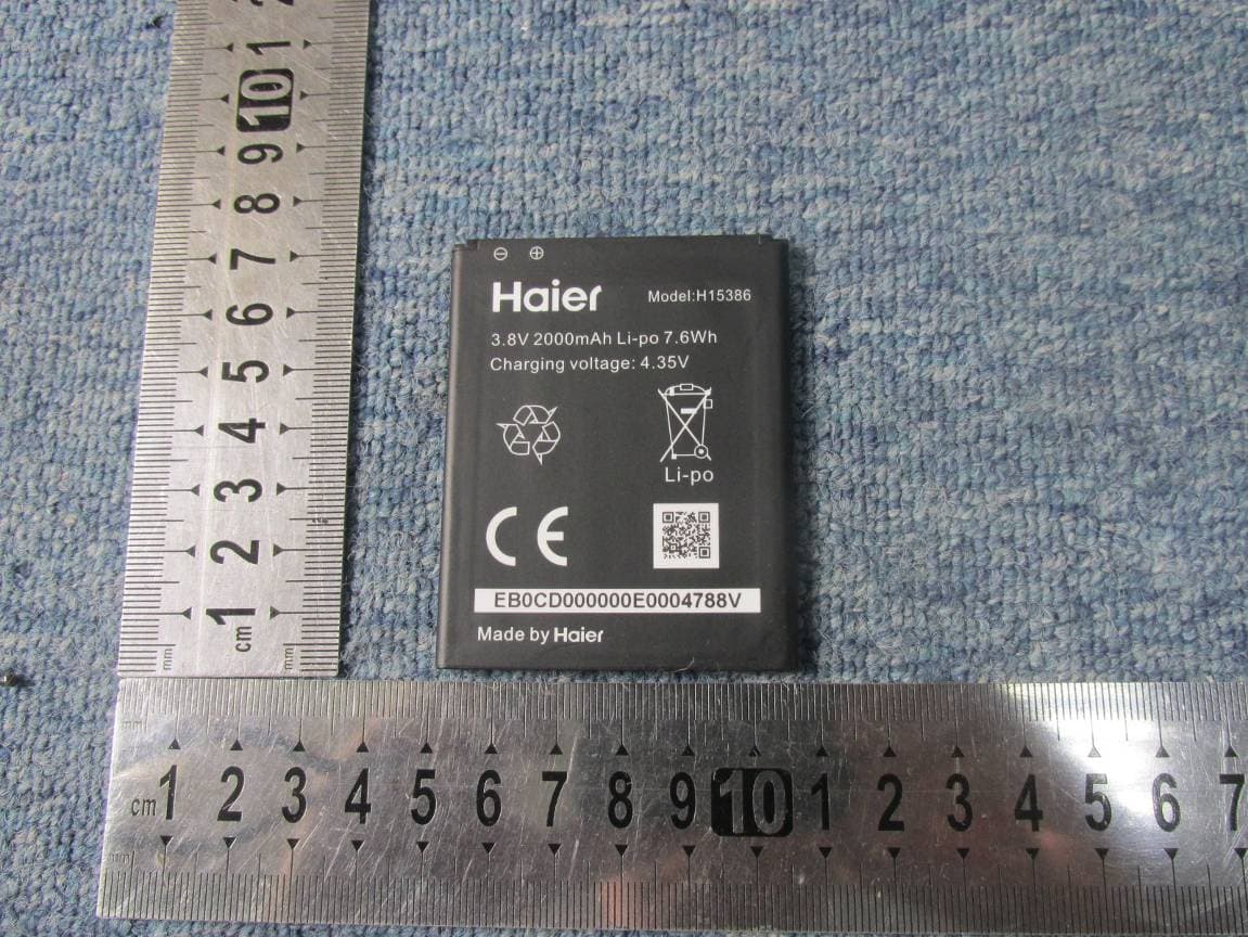
SG7201511L50
Dec 07, 2015Mobile Phone
Equipment Class
DTS - Digital Transmission System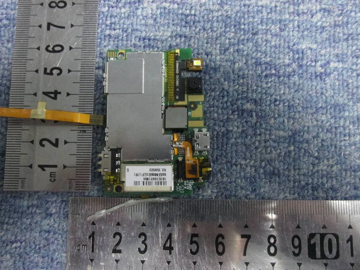
SG7201511L32
Dec 03, 2015Mobile Phone
Equipment Class
PCE - PCS Licensed Transmitter held to ear
SG71507L51
Dec 03, 2015L51
Equipment Class
DTS - Digital Transmission System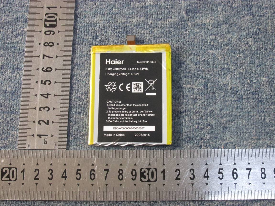
SG720151015I70
Nov 03, 2015Smart phone
Equipment Class
PCE - PCS Licensed Transmitter held to ear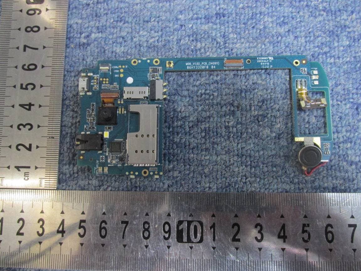
SG720151010G10
Oct 22, 2015Mobile phone
Equipment Class
DSS - Part 15 Spread Spectrum Transmitter