SGI-WL500Remote control for hearing instruments
Sivantos GmbH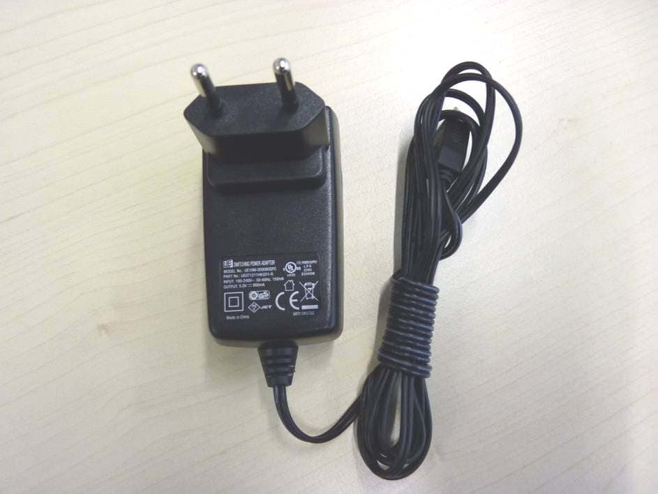
Click to zoom
Application Details
- Equipment Class
- DSS - Part 15 Spread Spectrum Transmitter
- Date of Grant
- Feb 24, 2011
- Application Purpose
- Original Equipment
- Date of Application
- Feb 24, 2011
- Equipment Note
- Remote control for hearing instruments
- Frequency Range
- 2402.00000000 - 2480.00000000
- Company
- Sivantos GmbH
- Country
- Germany
Documents & Files
Document Text
Text extracted from the exhibit documents filed with the FCC. Open a document above to read the original.
Users Manual
miniTek remote control • távirányító • telecomandă • télécommande • Fernbedienung • miniTek English Magyar Română Français Deutsch عربي 2 English3 Magyar33 Română61 Français89 Deutsch121 عربي 153 3 Content EN HU RO FR DE AR Content miniTek 4 Intended use 8 General notes on safety 9 Basic functions 12 Bluetooth 16 Using miniTek with cell phones and landline phones 17 Using the transmitter 19 Using the line-in audio input 23 Using miniTek with a third party Bluetooth transmitter 24 Using miniTek with a public loop system 26 Accessories 27 Maintenance and care 28 Disposal information 29 Technical information 30 miniTek 4 miniTek miniTek 5 EN HU RO FR DE AR ① Telephone button ② Stand-by for hearing instruments; mute ③ miniTek on/off ④ Audio source button ⑤ Volume up / volume down ⑥ Program change button ⑦ 2.5 mm stereo socket ⑧ DAI port for FM receiver ⑨ Socket for power plug ⑩ Microphone openings ⑪ Slots for fi xing the clip ⑫ Lanyard attachment ⑬ Power LED miniTek 6 Included in delivery ■ miniTek with lanyard and clip ■ Transmitter ① On/off switch ② Sound level ③ Socket for power plug ④ 2.5 mm stereo socket ⑤ LED ■ 2 Power plugs with country specifi c adapters (one for remote control, one for Transmitter) miniTek 7 EN HU RO FR DE AR ■ Cables: □ 1.8 m audio cable with 3.5 mm stereo plug on one side and a 2.5 mm stereo plug on the other side □ 0.3 m audio cable with 3.5 mm stereo plug on one side and a 2.5 mm stereo plug on the other side ■ Adapter set: □ 2.5 mm stereo plug to 3.5 mm stereo socket □ 6.3 mm stereo plug to 3.5 mm stereo socket □ RCA (cinch) to 3.5 mm stereo socket □ RCA (cinch) to SCART Intended use 8 This remote control is intended to operate hearing instruments. Read and follow the instructions of this user guide to avoid injuries or damage to remote control. Symbols: Be aware of information marked with the warning symbol WARNING, CAUTION or NOTICE! WARNING points out a situation that could lead to serious injuries, CAUTION indicates a situation that could lead to minor and moderate injuries. NOTICE NOTICE indicates possible property damage. Advice and tips on how to handle your device better. Instruction. Indicates that something has to be done. Intended use 9 EN HU RO FR DE AR General notes on safety WARNING Wireless systems may interfere with measuring devices and electronic equipment. Turn the remote control off when in hospitals or airplanes. Prior to use in conjunction with an electronic implant or life supporting system, have the electromagnetic compatibility verifi ed. NOTICE The remote control is sensitive to extreme heat, high humidity, strong magnetic fi elds (> 0.1T), X-rays and mechanical stress. Do not expose the remote control to extreme temperature or high humidity. Do not leave it in direct sunlight. Do not immerse it in water. Do not place your remote control in a micro- wave oven. NOTICE Operating temperature: charge min. 0°C to max. 45°C; discharge min. -20°C to max. 60°C Storage conditions: min. -20°C to max. 60°C; low humidity General notes on safety 10 General notes on safety In some countries restrictions for the usage of wireless equipment exist. Refer to local authorities for further informa- tion. The performance of the e2e wireless function may be affected by electromagnetic interference – e.g. from a computer monitor or fl uorescent lamp system. Move away from the source of interference if you experience diffi culty. In the event your hearing instruments can be controlled by another person's remote control, return hearing instruments and remote control to your Hearing Care Professional. WARNING Risk of interference with cardiac pacemakers. Do not use the remote control if you are fi tted with a cardiac pacemaker. WARNING Hazard of explosion in gas-fi lled spaces! Do not use your hearing instruments and re- mote control in areas where there is danger of explosions (e.g. mining). 11 EN HU RO FR DE AR General notes on safety WARNING Strangulation hazard when lanyard gets entangled in e.g. moving mechanical parts of machines. Use only the delivered breakaway lanyard. It will automatically detach when entangled. WARNING Choking hazard posed by small parts. Keep batteries, small parts and remote control out of children‘s reach. If swallowed consult a physician or hospital im- mediately. NOTICE Use only original Siemens power adapter (model no. KSAA0500080W1UV-1; input: 100-240V ~, 50- 60 Hz, 180 mA, output: 5 V, 800 mA, protection class II, only for indoor use). NOTICE Please make sure that the power plug is easily ac- cessible to remove it from power supply if neces- sary. Basic functions 12 Before fi rst use Charge miniTek before fi rst use. Charging Connect miniTek with the power plug to a power sup- ply. Charging is complete when the power LED shines green. Power LED state Battery fullBattery nearly empty miniTek offoffoff miniTek onfl ashes greenfl ashes red miniTek off/ charging green constantlyred constantly miniTek on/ charging pulses greenpulses red Turning off miniTek green / turns off slowly red / turns off slowly Turning on miniTek green for 3 seconds, then fl ashes green red for 3 seconds, then fl ashes red If you turn on miniTek and the battery is empty, the LED rapidly fl ashes red for 3 seconds, then turns off. Basic functions Basic functions 13 EN HU RO FR DE AR Wearing miniTek Wear miniTek no further than 60 cm (24 inches) away from the hearing instruments. Use lanyard or clip to wear miniTek. Turning the miniTek on/off Press for about 3 seconds to turn miniTek on. All LEDs shine for 3 seconds, then only the power LED shines. Press for about 3 seconds to turn miniTek off. All LEDs shine for 3 seconds, then turn off slowly. Changing the hearing program Press to change the hearing program. Each time you press the program button, your hearing instruments switch to the next program, confi rming each change with an acoustic signal. Changing the volume Press to increase the volume. Press to decr…
Text truncated - open the document above for the full version.
External Photos
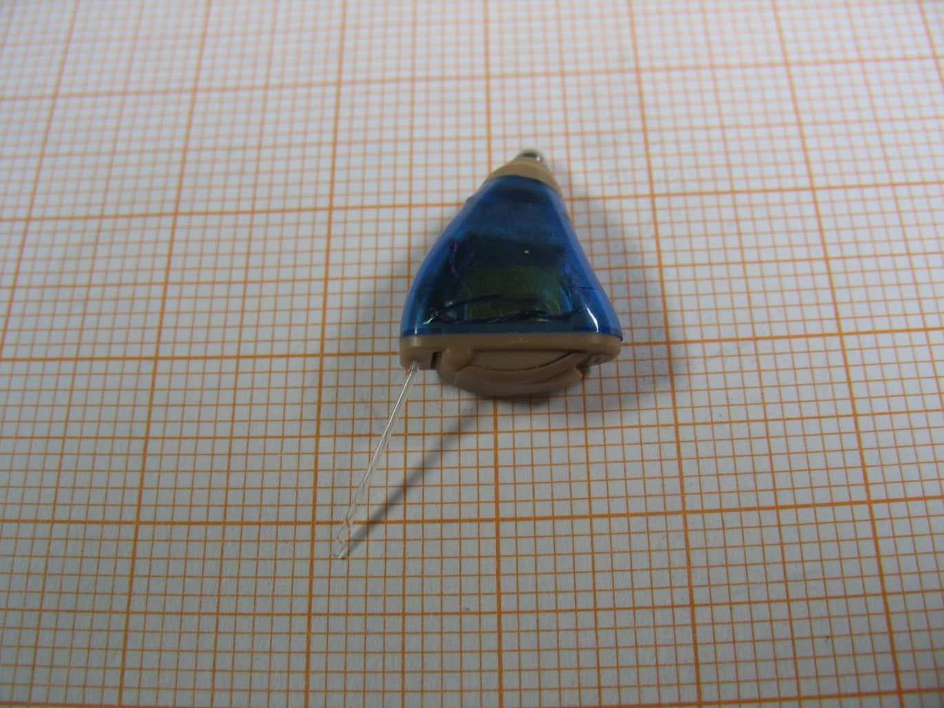
Test report no.: 1-1383-01-20/09-A 2010-12-06 Page 64 of 71 Annex B Internal and External Photographs of the EUT Photo 3 (identical in construction to tested samples): Photo 4 (identical in construction to tested samples): Test report no.: 1-1383-01-20/09-A 2010-12-06 Page 65 of 71 Photo 5 (identical in construction to tested samples): Photo 6 (identical in construction to tested samples): Test report no.: 1-1383-01-20/09-A 2010-12-06 Page 66 of 71 Photo 7 (identical in construction to tested samples): Photo 8 (identical in construction to tested samples):
Internal Photos
Test report no.: 1-1383-01-20/09-A 2010-12-06 Page 67 of 71 Photo 9 (identical in construction to tested samples): Photo 10 (identical in construction to tested samples): Test report no.: 1-1383-01-20/09-A 2010-12-06 Page 68 of 71 Photo 11 (identical in construction to tested samples): Test report no.: 1-1383-01-20/09-A 2010-12-06 Page 69 of 71 Photo 12: (conducted sample Basic Rate) Photo 13: (conducted sample Basic Rate)
Test Report
2011-02-24 Page 1 of 71 TEST REPORT Test Report No.: 1-1383-01-20/09-A Testing Laboratory Applicant CETECOM ICT Services GmbH Untertürkheimer Straße 6 – 10 66117 Saarbrücken/Germany Phone: + 49 681 5 98 - 0 Fax: + 49 681 5 98 - 9075 Internet: http://www.cetecom.com e-mail: [email protected] Accredited Test Laboratory: The test laboratory (area of testing) is accredited according to DIN EN ISO/IEC 17025 DAR registration number: DGA-PL-176/94-D1 Area of Testing: Radio Satellite Communications SIEMENS Audiologische Technik GmbH Basic Technology (AEBT) Gebbertstrasse 125 91058 Erlangen/GERMANY Fax: +49 9131 308-3207 Contact: Clemens Meythaler e-mail: [email protected] Phone: +49 9131 308-3000 Manufacturer SIEMENS Audiologische Technik GmbH Basic Technology (AEBT) Gebbertstrasse 125 91058 Erlangen/GERMANY Test Standard/s 47 CFR Part 15 Title 47 of the Code of Federal Regulations; Chapter I-Federal Communications Commission subchapter A - general, Part 15-Radio frequency devices RSS - 210 Issue 7 Spectrum Management and Telecommunications - Radio Standards Specification Low-power Licence-exempt Radiocommunication Devices (All Frequency Bands): Category I Equipment For further applied test standards please refer to section 3 of this test report. Test Item Kind of test item: MiniTEK Model name: MiniTEK / Mini Blu RCU FCC ID: SGI-WL500 IC: 267AB- WL500 Frequency [MHz]: 2402 - 2480 Power supply: 3.7V DC by Li-Ion Battery Temperature range: -20 °C to 55 °C This test report is electronically signed and valid without handwriting signature. For verification of the electronical signatures, the public keys can be requested at the testing laboratory. Test performed: Test Report authorised: Jakob Reschke Joerg Warken Test report no.: 1-1383-01-20/09-A 2011-02-24 Page 2 of 71 1 Table of contents 1 Table of contents............................................................................................................................................2 2 General Information .......................................................................................................................................3 2.1 Notes.....................................................................................................................................................3 2.2 Application details...............................................................................................................................3 3 Test standard/s ...............................................................................................................................................3 4 Test Environment ...........................................................................................................................................3 5 Test item ..........................................................................................................................................................4 6 Test Laboratories sub-contracted ................................................................................................................4 7 Summary of measurement results ...............................................................................................................5 8 RF measurement testing................................................................................................................................6 8.1 Description of test setup ....................................................................................................................6 8.1.1 Radiated measurements.............................................................................................................6 8.1.2 Conducted measurements..........................................................................................................7 8.2 Additional comments ..........................................................................................................................7 8.3 RSP100 Test Report Cover Sheet / Performance Test Data............................................................8 9 Measurement Results ....................................................................................................................................9 9.1 Antenna Gain .......................................................................................................................................9 9.2 Power Spectral Density.....................................................................................................................10 9.3 Carrier Frequency Separation ..........................................................................................................11 9.4 Number of Hopping Channels..........................................................................................................13 9.5 Time of Occupancy (Dwell Time) .....................................................................................................15 9.6 Spectrum Bandwidth of a FHSS System – 20 dB Bandwidth .......................................................16 9.7 Maximum Output Power ...................................................................................................................20 9.8 Band Edge Compliance Conducted ................................................................................................25 9.9 Band Edge Compliance Radiated ....................................................................................................33 9.10 TX Spurious Emissions Conducted .............................................................................................38 9.11 TX Spurious Emissions Radiated ................................................................................................44 9.12 RX Spurious Emissions Radiated ................................................................................................52 9.13 TX Spurious Emissions Radiated < 30 MHz ..............................................................…
Text truncated - open the document above for the full version.
Test Setup Photos
Test report no.: 1-1383-01-20/09-A 2010-12-06 Page 63 of 71 Annex A Photographs of the Test Set-up Photo 1: Photo 2:
Contact Information
Applicant
Juergen Reithinger
Test Firm
cetecom advanced GmbHGerald Schmidt
Technical Specifications
| # | Rule Parts | Frequency Range | Power Output |
|---|---|---|---|
| 1 | 15C | 2.40 GHz - 2.48 GHz | 2.20 mW |
Other Applications from Sivantos GmbH
SGI-MIM002
Mar 17, 2020NFMI Module 2
Equipment Class
DXX - Part 15 Low Power Communication Device Transmitter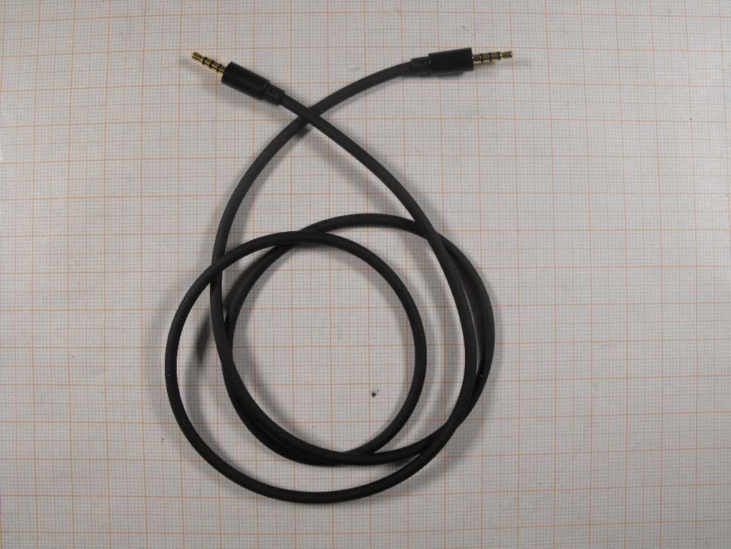
SGI-WL401
Apr 23, 2015Remote Controller
Equipment Class
DXX - Part 15 Low Power Communication Device Transmitter
SGI-WL003BTE
Jul 15, 2014BTE Hearing Aid
Equipment Class
DXX - Part 15 Low Power Communication Device Transmitter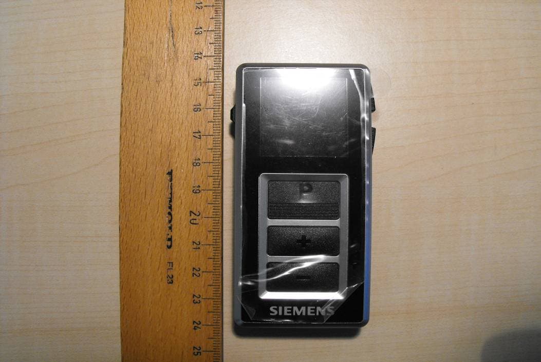
SGI-WL700
Feb 04, 2013easyPocket remote control 3.28 MHz
Equipment Class
DXX - Part 15 Low Power Communication Device TransmitterSGI-WL201AP
Jun 27, 2011Remote Control Device
Equipment Class
DXX - Part 15 Low Power Communication Device Transmitter