SH6PE1000Wireless ExpressCard Presenter
Raytac Corp.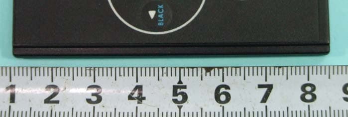
Click to zoom
Application Details
- Equipment Class
- DXX - Part 15 Low Power Communication Device Transmitter
- Date of Grant
- Apr 13, 2008
- Application Purpose
- Original Equipment
- Date of Application
- Apr 13, 2008
- Equipment Note
- Wireless ExpressCard Presenter
- Frequency Range
- 2405.00000000 - 2480.00000000
- Company
- Raytac Corp.
- Country
- Taiwan
Documents & Files
Document Text
Text extracted from the exhibit documents filed with the FCC. Open a document above to read the original.
Users Manual
1 Wireless ExpressCard Presenter (ExpressCard Size) User’s Guide Information in this document is subject to change without notice. No part of this document may be reproduced or transmitted in any form or by any means, electronic or mechanical, for any purpose, without the express written prior permission of the seller. The seller provides this document without warranty, or condition of any kind. The seller may make improvements or change in the product described in this documentation at any time. Other product and company name herein may be the trademarks of their respective owners. c 2007 All rights reserved. Be sure to carefully read this User’s Guide first for the proper use of the Wireless ExpressCardPresente r and keep it for future reference. 2 IMPORTANT SAFETY AND HEALTH INFORMATION WARNING! RISK OF INJURY! Laser beam can cause permanent damage to eyes. Do not look into the laser beam or shine the laser beam into your eyes, other peoples’ eyes, or pet’s eyes. WARNING! RISK OF INJURY! Keep this device away from Children. This is a working tool, not a toy or entertainment device. It should only be used by adults. NOTE This equipment has been tested and found to comply with the limits for a Class B digital device, pursuant to Part 15 of the FCC Rules. These limits are designed to provide reasonable protection against harmful interference in a residential installation. This equipment generates, uses and can radiated radio frequency energy and, if not installed and used in accordance with the instructions, may cause harmful interference to radio communications. However, there is no guarantee that interference will not occur in a particular installation If this equipment does cause harmful interference to radio or television reception, which can be determined by turning the equipment off and on, the user is encouraged to try to correct the interference by one or more of the following measures: -Reorient or relocate the receiving antenna. -Increase the separation between the equipment and receiver. -Connect the equipment into an outlet on a circuit different from that to which the receiver is connected. -Consult the dealer or an experienced radio/TV technician for help. Changes or modifications not expressly approved by the party responsible for compliance could void the user’s authority to operate the equipment. 3 This device complies with Part 15 of the FCC Rules. Operation is subject to the following two conditions:(1) this device may not cause harmful interference, and (2) this device must accept any interference received, including interference that may cause undesired operation. This device and its antenna(s) must not be co-located or operating in conjunction with any other antenna or transmitter. Thank you for choosing the Wireless ExpressCard Presenter —“Make Your Presentation Easier and More Effective” Introduction of Wireless ExpressCard Presenter The Wireless ExpressCard Presenter is the mixed of RF wireless control of PowerPoint shortcuts and build-in laser point. The Presenter enables the user to control presentation slides wirelessly up to 66 feet (20M). The Presenter is a USB plug-and-play device with no additional software required and featured with low-battery warning. The USB receiver is designed slim enough to snap into the main body and fit the whole wireless presenter into the ExpressCard/34 or ExpressCard/54 slot of your notebook PC. You can also use the supplied PCMCIA card boat to fit it in your PCMCIA card slot. (Please refer to "How to use the PCMCIA card boat".) What’s included Wireless ExpressCard Presenter (with USB receiver) 1 CR2032 battery 1 User’s Manual 1 PCMCIA Card Boat 1 System Requirements Windows® 2000/XP/Windows Vista TM PC 4 An available USB port How to use the PCMCIA Card Boat The Wireless ExpressCard Presenter can be stored in the ExpressCard slot directly. In case your computer is equipped with PCMCIA slot, please place the Presenter in the boat and then store it in your PCMCIA card slot. Place the Presenter in the boat Insert the bottom of the USB receiver, label upwards, into the compartment and press the USB receiver to the compartment. Take out the Presenter form the boat Pull up the Presenter from its top and take out the receiver. Initial set up for the Wireless ExpressCard Presenter Step 1: Insert the supplied battery CR2032 with (+) side up into the battery compartment in back of Presenter. Step 2: Remove the USB receiver from back of Presenter and plug into an available USB port on your PC, the Presenter is ready to use. Take out the USB receiver Pull up the USB receiver from its top and take out the receiver. Put back the USB receiver Insert the bottom of the USB receiver, label upwards, into the compartment and press the USB receiver to the compartment. 5 Operating the Wireless ExpressCard Presenter Button with white character Function How to operate LASER Press to emit the laser beam. Slides Press to start slide show. ESC Press to exit slide show. Next Press to go to next slide. Prev. Press to go to previous slide. Note: The FN button is used in combination with the other buttons (blue character) for special PowerPoint function as the following. Button with blue character Function How to operate Fn + Black screen black Press to turn the whole screen black. Press Next button returns to normal. Fn + White screen white Press to turn the whole screen white. Press Next button returns to normal. Fn + Alt+Tab Change presentation program/files Press and hold Fn button, click Alt+Tab to select the file, then release Fn button to swap to the file selected. Front ViewRear View 6 Fn + Link Change ID Please see “How to pair the Wireless ExpressCard Presenter”. Note: Implement ID change ONLY when serious RF interference causes the remote control malfunction. Note: The low battery indicator on the Presenter will light up when the power is running low, it is probably time to replace battery whenever you see the low battery i…
Text truncated - open the document above for the full version.
External Photos
FCC TEST REPORT SPORTON International Inc. PAGE NUMBER : B1 OF B5 TEL : 886-2-2696-2468 ISSUED DATE : Apr. 09, 2008 FAX : 886-2-2696-2255 APPENDIX B. Photographs of EUT FCC TEST REPORT SPORTON International Inc. PAGE NUMBER : B2 OF B5 TEL : 886-2-2696-2468 ISSUED DATE : Apr. 09, 2008 FAX : 886-2-2696-2255
ID Label/Location Info
PE1000-TX Label C A U T I O N The device complies Part 15 of the FCC Rules. RoHS LASER RADIATION-DO NOT STARE INTO BEAM MAX OUTPUT:1mW WAVE LENGTH:650±20nm CLASS II LASER PRODUCT. This product complies with 21 CFR. Made in Taiwan FCC ID:SH6PE1000 Model No.:PE1000 Trade Name: RAYTAC FCC ID:SH6PE1000 2mm 10mm 33mm CAUTION T h e d e v i c e c o m p l i e s P a r t 1 5 o f t h e F C C R u l e s . R o H S L A S E R R A D I A T I O N - D O N O T S T A R E I N T O B E A M M A X O U T P U T : 1 m W W A V E L E N G T H : 6 5 0 ± 2 0 n m C L A S S I I L A S E R P R O D U C T . T h i s p r o d u c t c o m p l i e s w i t h 2 1 C F R . M a d e i n T a i w a n F C C I D : S H 6 P E 1 0 0 0 M o d e l N o . : P E 1 0 0 0 T r a d e N a m e : R A Y T A C
Internal Photos
FCC TEST REPORT SPORTON International Inc. PAGE NUMBER : B2 OF B5 TEL : 886-2-2696-2468 ISSUED DATE : Apr. 09, 2008 FAX : 886-2-2696-2255 FCC TEST REPORT SPORTON International Inc. PAGE NUMBER : B3 OF B5 TEL : 886-2-2696-2468 ISSUED DATE : Apr. 09, 2008 FAX : 886-2-2696-2255 FCC TEST REPORT SPORTON International Inc. PAGE NUMBER : B4 OF B5 TEL : 886-2-2696-2468 ISSUED DATE : Apr. 09, 2008 FAX : 886-2-2696-2255 PIFA Antenna FCC TEST REPORT SPORTON International Inc. PAGE NUMBER : B5 OF B5 TEL : 886-2-2696-2468 ISSUED DATE : Apr. 09, 2008 FAX : 886-2-2696-2255
Test Report
FCC TEST REPORT Report No.: FR832021 SPORTON International Inc. Report Format Version: a FCC RADIO TEST REPORT according to 47 CFR FCC Part 15 Subpart C § 15.249 Equipment : Wireless ExpressCard Presenter Model No. : PE1000 Brand Name : Raytac Filing Type : New Application Applicant : Raytac Corp. 12F, No.786, Zhongzheng Rd., Zhonghe City, Taipei County 23586, Taiwan FCC ID : SH6PE1000 Manufacturer : Taicom Data Systems Co. Ltd. No. 45, Wu-Kung 5th Rd., Wu-Ku Industrial Park, Wu-Ku Hsiang, Taipei Hsien, Taiwan, R.O.C. Received Date : Mar. 27, 2008 Final Test Date : Mar. 28, 2008 Statement The test result in this report refers exclusively to the presented test model / sample. Without written approval of SPORTON International Inc., the test report shall not be reproduced except in full. The measurements and test results shown in this test report were made in accordance with the procedures and found in compliance with the limit given in ANSI C63.4-2003 and 47 CFR FCC Part 15 Subpart C. The test equipment used to perform the test is calibrated and traceable to NML/ROC. SPORTON International Inc. 6F, No. 106, Sec. 1, Hsin Tai Wu Rd., Hsi Chih, Taipei Hsien, Taiwan, R.O.C. ILAC MRA FCC TEST REPORT Report No.: FR832021 SPORTON International Inc. Page No. : i of ii TEL : 886-2-2696-2468 Issued Date : Apr. 09, 2008 FAX : 886-2-2696-2255 FCC ID : SH6PE1000 Table of Contents 1. SUMMARY OF THE TEST RESULT ...................................................................................................................... 2 2. GENERAL INFORMATION..................................................................................................................................... 3 2.1. Product Details ........................................................................................................................................................................................ 3 2.2. What’s included ....................................................................................................................................................................................... 3 2.3. Table for Carrier Frequencies ................................................................................................................................................................. 3 2.4. Table for Test Modes .............................................................................................................................................................................. 4 2.5. Table for Testing Locations ..................................................................................................................................................................... 4 2.6. Table for Supporting Units....................................................................................................................................................................... 4 2.7. Test Configurations ................................................................................................................................................................................. 5 3. TEST RESULT ........................................................................................................................................................ 7 3.1. AC Power Line Conducted Emissions Measurement.............................................................................................................................. 7 3.2. Field Strength of Fundamental Emissions Measurement...................................................................................................................... 10 3.3. 20dB Spectrum Bandwidth Measurement............................................................................................................................................. 13 3.4. Radiated Emissions Measurement........................................................................................................................................................ 16 3.5. Band Edge Emissions Measurement .................................................................................................................................................... 28 3.6. Antenna Requirements.......................................................................................................................................................................... 30 4. LIST OF MEASURING EQUIPMENTS ................................................................................................................. 31 5. TEST LOCATION.................................................................................................................................................. 32 6. TAF CERTIFICATE OF ACCREDITATION .......................................................................................................... 33 APPENDIX A. TEST PHOTOS ........................................................................................................................ A1 ~ A4 APPENDIX B. PHOTOGRAPHS OF EUT ....................................................................................................... B1 ~ B5 FCC TEST REPORT Report No.: FR832021 SPORTON International Inc. Page No. : ii of ii TEL : 886-2-2696-2468 Issued Date : Apr. 09, 2008 FAX : 886-2-2696-2255 FCC ID : SH6PE1000 History of This Test Report Original Issue Date: Apr. 09, 2008 Report No.: FR832021 ■ No additional attachment. □ Additional attachment were issued as following record: Attachment No. Issue Date Description 15.205(a) 15.209(a) 47 CFR FCC Part 15 Subpart C Further, this requirement does not apply to intentional radiators that must be professionally installed. FCC TEST REPORT Report No.: FR832021 SPORTON International Inc. Page No. : 2 of 33 TEL : 886-2-2696-2468 Issued Date : Apr. 09, 2008 FAX : 886-2-2696-2255 FCC ID : SH6PE1000 1. SUMMARY OF THE TEST RESULT Applied Standard: 47 CFR FCC Part 15 Subpart C Part Rule Section Description of Test Result …
Text truncated - open the document above for the full version.
Test Setup Photos
FCC TEST REPORT Report No.: FR832021 Page No. : A1 of A4 FCC ID : SH6PE1000 Appendix A. Test Photos FCC TEST REPORT Report No.: FR832021 Page No. : A2 of A4 FCC ID : SH6PE1000 1. Photographs of Radiated Emissions Test Configuration For radiated emissions 9kHz~30MHz FRONT VIEW REAR VIEW FCC TEST REPORT Report No.: FR832021 Page No. : A3 of A4 FCC ID : SH6PE1000 For radiated emissions 30MHz~1GHz FRONT VIEW REAR VIEW FCC TEST REPORT Report No.: FR832021 Page No. : A4 of A4 FCC ID : SH6PE1000 For radiated emissions above 1GHz FRONT VIEW REAR VIEW
Contact Information
Applicant
Lyon Liu(President)
Technical Contact
Sporton International Inc.Wayne Hsu
No. 52. Hwa Ya 1st Rd., Hwa Ya Technology Park · Tao Yuan · Taiwan
Test Firm
Sporton International Inc.Alex Chen
Technical Specifications
| # | Rule Parts | Frequency Range | Power Output |
|---|---|---|---|
| 1 | 15C | 2.40 GHz - 2.48 GHz | - |
Other Applications from Raytac Corp.
SH6MDBT42T
Nov 15, 2020BLE Module
Equipment Class
DTS - Digital Transmission System
SH6MD85XXP1
Jul 21, 2015Wireless Audio Module
Equipment Class
DTS - Digital Transmission System
SH6MDBT40
Feb 16, 2014Bluetooth Module
Equipment Class
DTS - Digital Transmission System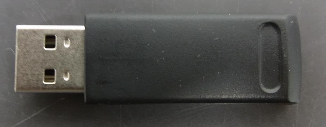
SH6MP01R
Dec 16, 2013WIRELESS PRESENTER
Equipment Class
DXX - Part 15 Low Power Communication Device Transmitter
SH6MP01
Dec 12, 2013WIRELESS PRESENTER
Equipment Class
DXX - Part 15 Low Power Communication Device Transmitter