SJC-M1010EVMWireless Tracking System
Analog Devices LLC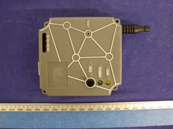
Click to zoom
Application Details
- Equipment Class
- DXX - Part 15 Low Power Communication Device Transmitter
- Date of Grant
- Sep 30, 2004
- Application Purpose
- Original Equipment
- Date of Application
- Sep 30, 2004
- Equipment Note
- Wireless Tracking System
- Frequency Range
- 903.01800000 - 926.97960000
- Company
- Analog Devices LLC
- Country
- Ireland
Documents & Files
Document Text
Text extracted from the exhibit documents filed with the FCC. Open a document above to read the original.
Users Manual
Dust Networks D1100/ M1010EVM Evaluation Kit Quick Start Guide D1100 EVALUATION KIT QUICK START GUIDE Trademarks Dust Networks, the Dust Networks logo, and SmartMesh are trademarks of Dust Networks, Inc. All third party brand and product names are the trademarks of their respective owners and are used solely for informational purposes. Copyright This documentation is protected by United States and international copyright and other intellectual and industrial property laws. It is solely owned byDust Networks, Inc. and its licensors and is distributed under a restrictive license. This product, or any portion thereof, may not be used, copied, modified, reverse assembled, reverse compiled, reverse engineered, distributed or redistributed in any form by any means without the prior written authorization of Dust Networks, Inc. RESTRICTED RIGHTS: Use, duplication, or disclosure by the U.S. Government is subject to restrictions of FAR 52.227-14(g) (2)(6/87) and FAR 52.227-19(6/87), or DFAR 252.227-7015 (b)(6/95) and DFAR 227.7202-3(a) and any and all similar and successor legislation and regulation. Disclaimer THIS DOCUMENTATION IS PROVIDED “AS IS” WITHOUT WARRANTY OF ANY KIND, EITHER EXPRESSED OR IMPLIED, INCLUDING BUT NOT LIMITED TO, THE IMPLIED WARRANTIES OF MERCHANTABILITY OR FITNESS FOR A PARTICULAR PURPOSE. THIS DOCUMENTATION MIGHT INCLUDE TECHNICAL INACCURACIES OR OTHER ERRORS. CORRECTIONS AND IMPROVEMENTS MIGHT BE INCORPORATED IN NEW VERSIONS OF THE DOCUMENTATION. FCC Warning The FCC has developed guidelines to reduce any possible hazard due to exposure of the human body to electromagnetic radiation (such as radio waves). In accordance with these guidelines, the antenna should be positioned at a distance greater than 4 cm (1.57in) from users and bystanders, 2 cm (.79 in) from hands, wrists, feet, and ankles when the device is transmitting. EMI Warning This equipment has been tested and found to comply with the limits pursuant to Part 15 of the FCC rules. These limits are designed to provide reasonable protection against harmful interference in an appropriate installation. This equipment generates, uses, and can radiate radio frequency energy and, if not installed and used in accordance with the instructions, may cause harmful interference to radio communication. However, there is no guarantee that interference will not occur in a particular installation. If this equipment does cause harmful interference to radio or television reception, which can be determined by turning the equipment off and on, the user is encouraged to try to correct the interference by one or more of the following measures: (1) Reorient or relocate the receiving antenna. (2) Increase the separation between the equipment and receiver (3) Connect the equipment into an outlet on a circuit different from that to which the receiver is connected. (4) Consult the dealer or an experienced radio or television technician for assistance. Contents D1100 EVALUATION KIT QUICK START GUIDEi About This Guide Related Documents.......................................................................... iii Conventions Used.............................................................................. iii 1 M1010 Evaluation Module M1010 Evaluation Module........................................................... 1 Connector P1.......................................................................................... 2 Connector P2.......................................................................................... 3 Serial Interface.................................................................................... 4 Power Supply......................................................................................... 4 Absolute Maximum Ratings........................................................ 4 Recommended Operating Conditions................................. 5 Wireless Specifications.................................................................. 5 Antenna...................................................................................................... 5 Regulatory Information................................................................ 6 2 SmartMesh Manager Description............................................................................................... 7 Connections............................................................................................. 8 Technical Specifications................................................................ 8 Regulatory Information................................................................ 9 3 Setting Up a Network Setting Up the SmartMesh Manager................................. 11 Setting Up the Network............................................................... 11 TABLE OF CONTENTS iiD1100 EVALUATION KIT QUICK START GUIDE D1100 EVALUATION KIT QUICK START GUIDEiii About This Guide This guide provides information required to successfully demonstrate the capabilities of the D1100 Evaulation Kit. It provides various pinout and connector information for attaching sensors to a M1010 Evaluation Module and instructions for setting up a network. Related Documents The following documents are available for a SmartMesh Network: •D1100 Evaluation Kit Quick Start Guide (this guide) •SmartMesh Manager Application Programming Interface (API) Guide •M1010 Mote Integration Guide •SmartMesh Network Planning Guide •SmartMesh Network Administration Guide Conventions Used The following conventions are used in this guide: •Computer type indicates information that you enter, such as specifying a URL. •Bold type indicates buttons, fields, and menu commands. •Italic type is used to introduce a new term. dNote: Notes provide more detailed information about concepts. bCautions: Cautions advise you about actions that might result in a loss of data. cWarning! Warnings advise you about actions that may cause physical harm to the hardware or your person. CHAPTER 1 - ABOUT THIS GUIDEConvention…
Text truncated - open the document above for the full version.
Cover Letter(s)
2560 Ninth Street, Suite 220 Berkeley, California 94710 www.dustnetworks.com September 27, 2004 Bay Area Compliance Laboratory Corp. 230 Commercial Street Sunnyvale, CA 94085 Re: Confidentiality of FCC Filings Dear Sir/Madam, We, Dust Networks, Inc. request that you file the appropriate paperwork requesting for confidentiality of the data contained in the applications for the following project(s): SmartMesh™ Manager - D1100 M1010 Mote Evaluation Module - M1010EVM Specifically, we would like any documents that contain schematics, block diagrams, circuit descriptions, technical specifications, or any other data that can be maintained confidential under FCC rules. Sincerely, Jonathan Simon Dir. Hardware Engineering
External Photos
EXHIBIT C - EUT EXTERNAL PHOTOGRAPHS EUT – Top View EUT – Bottom View
ID Label/Location Info
EXHIBIT A - FCC ID LABEL INFORMATION Proposed FCC ID Label Specifications : Text is black or white in color and is left justified. Labels are silk- screened and shall be “permanently affixed” at a conspicuous location on the EUT. Proposed Label Location on EUT Bottom View of EUT / FCC ID Label FCC ID: SJC-M1010EVM This device complies with Part 15 of the FCC Rules. Operation is subject to the following two conditions: (1) this device may not cause harmful interference, and (2) this device must accept any interference received, including interference that may cause undesired operation. 2.1875" 1.0" FCC ID: SJC-D1100 This device complies with Part 15 of the FCC Rules. Operation is subject to the following two conditions: (1) this device may not cause harmful interference, and (2) this device must accept any interference received, including interference that may cause undesired operation. 2 .1875" 1.0 "
Internal Photos
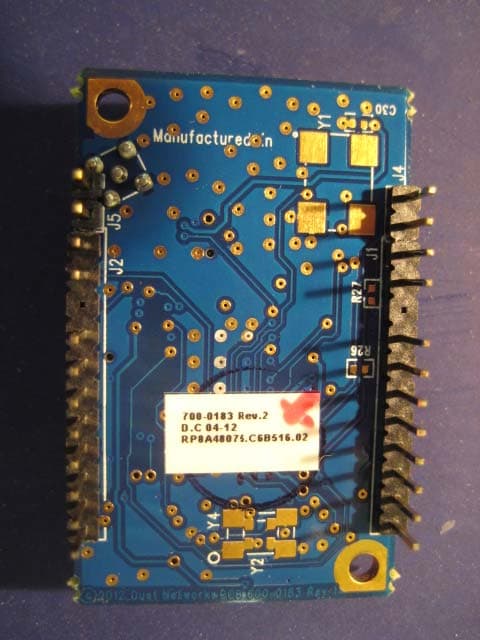
EXHIBIT C - EUT INTERNAL PHOTOGRAPHS EUT – Board and Housing View EUT – Component View EUT – Solder View
Test Report
Note: The test report is specially limited to the above company and the product model only. It may not be duplicated without prior written consent of Bay Area Compliance Laboratory Corporation. This report must not be used by the client to claim product certification, approval, or endorsement by NVLAP, NIST or any agency of the US Government. FCC PART 15.249 EMI MEASUREMENT AND TEST REPORT For Dust Networks, Inc. 2560 Ninth Street, Suite 220 Berkeley, CA 94710 FCC ID: SJC-M1010EVM This Report Concerns: Original Report Equipment Type: Blue Mote Test Engineer: Ling Zhang / Report No.: R04090111 Report Date: 2004-09-30 Reviewed By: Ming Jing / Prepared By: Bay Area Compliance Laboratory Corporation (BACL) 230 Commercial Street Sunnyvale, CA 94085 Tel: (408) 732-9162 Fax: (408) 732 9164 Dust Networks, Inc. FCC ID: SJC-M1010EVM Report # R04090111Rpt.doc Page 2 of 13 FCC Part 15.249 Test Report TABLE OF CONTENTS GENERAL INFORMATION.......................................................................................................................................3 PRODUCT DESCRIPTION FOR EQUIPMENT UNDER TEST (EUT) ....................................................................................3 OBJECTIVE...................................................................................................................................................................3 RELATED SUBMITTAL(S)/GRANT(S).............................................................................................................................3 TEST METHODOLOGY..................................................................................................................................................3 TEST FACILITY.............................................................................................................................................................3 SYSTEM TEST CONFIGURATION ..........................................................................................................................5 DESCRIPTION OF TEST CONFIGURATION......................................................................................................................5 EQUIPMENT MODIFICATIONS.......................................................................................................................................5 CONFIGURATION OF TEST SYSTEM..............................................................................................................................6 TEST SETUP BLOCK DIAGRAM.....................................................................................................................................6 SUMMARY OF TEST RESULTS ...............................................................................................................................7 §15.203 - ANTENNA REQUIREMENT......................................................................................................................8 STANDARD APPLICABLE..............................................................................................................................................8 ANTENNA CONNECTED CONSTRUCTION......................................................................................................................8 §15.209(A) - RADIATED EMISSION DATA .............................................................................................................9 MEASUREMENT UNCERTAINTY....................................................................................................................................9 EUT SETUP..................................................................................................................................................................9 SPECTRUM ANALYZER SETUP......................................................................................................................................9 TEST EQUIPMENT LIST AND DETAILS.........................................................................................................................10 ENVIRONMENTAL CONDITIONS..................................................................................................................................10 TEST PROCEDURE......................................................................................................................................................10 CORRECTED AMPLITUDE & MARGIN CALCULATION.................................................................................................10 SUMMARY OF TEST RESULTS.....................................................................................................................................11 §15.249(C) – BAND-EDGE TESTING ......................................................................................................................13 STANDARD APPLICABLE............................................................................................................................................13 TEST PROCEDURE......................................................................................................................................................13 TEST EQUIPMENT LIST AND DETAILS.........................................................................................................................13 ENVIRONMENTAL CONDITIONS..................................................................................................................................13 TEST RESULTS...........................................................................................................................................................13 Dust Networks, Inc. FCC ID: SJC-M1010EVM Report # R04090111Rpt.doc Page 3 of 13 FCC Part 15.249 Test Report GENERAL INFORMATION Product Description for Equipment Under Test (EUT) The Dust Networks, Inc.’s product, model no.: M1010EVM or the “EUT” as referred to this report is a b l u e m o t e which measures approximately 75mmL x 32mmW x 115mmH. The…
Text truncated - open the document above for the full version.
Test Setup Photos
EXHIBIT B - TEST SETUP PHOTOGRAPHS Radiated Emission
Contact Information
Applicant
David Bourke(Director of Hardware Engineering)
Test Firm
Bay Area Compliance LaboratoryJohn Chan
Technical Specifications
| # | Rule Parts | Frequency Range | Power Output |
|---|---|---|---|
| 1 | 15C | 903.018 MHz - 926.9796 MHz | - |
Other Applications from Analog Devices LLC
SJC-ETERNA1
Jan 17, 2013802.15.4 Wireless Mesh Mote
Equipment Class
DTS - Digital Transmission System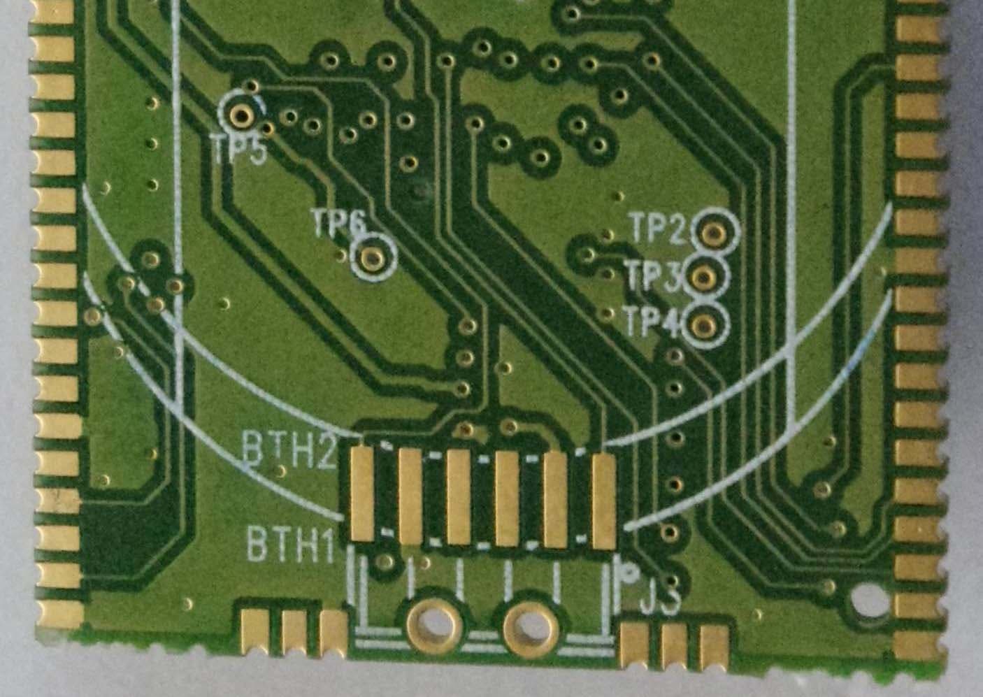
SJC-ETERNA2
Jan 17, 2013802.15.4 Wireless Mesh Mote
Equipment Class
DTS - Digital Transmission System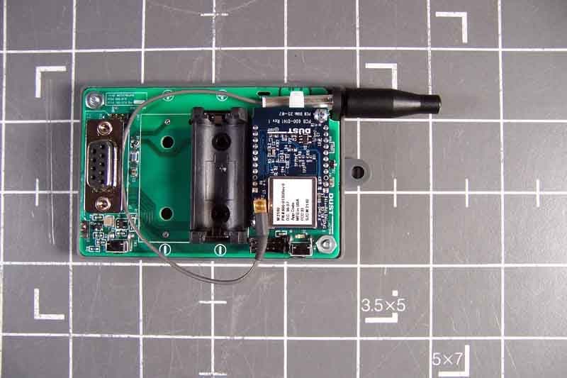
SJC-M2140
Dec 20, 2007Smart Mesh Wireless Mote
Equipment Class
DTS - Digital Transmission System
SJC-M1310
Apr 12, 2007900 MHz Mote Frequency Hopping System Module
Equipment Class
DSS - Part 15 Spread Spectrum Transmitter
SJC-M2030
Dec 15, 2006SmartMesh M2030 2.4GHz Mote
Equipment Class
DSS - Part 15 Spread Spectrum Transmitter