SJCM1030SmartMesh M1030 Mote
Analog Devices LLC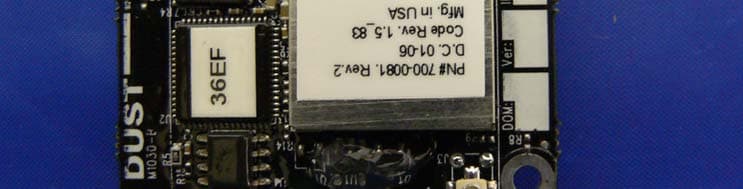
Click to zoom
Application Details
- Equipment Class
- DSS - Part 15 Spread Spectrum Transmitter
- Date of Grant
- Feb 15, 2006
- Application Purpose
- Original Equipment
- Date of Application
- Feb 15, 2006
- Equipment Note
- SmartMesh M1030 Mote
- Frequency Range
- 902.49000000 - 927.48000000
- Company
- Analog Devices LLC
- Country
- Ireland
Documents & Files
Document Text
Text extracted from the exhibit documents filed with the FCC. Open a document above to read the original.
Users Manual
Dust Networks Quick Start Guide for D1120 Network with M1030 Mote QUICK START GUIDE FOR D1120 NETWORK WITH M1030 MOTE Trademarks Dust Networks, the Dust Networks logo, and SmartMesh are trademarks of Dust Networks, Inc. All third party brand and product names are the trademarks of their respective owners and are used solely for informational purposes. Copyright This documentation is protected by United States and international copyright and other intellectual and industrial property laws. It is solely owned byDust Networks, Inc. and its licensors and is distributed under a restrictive license. This product, or any portion thereof, may not be used, copied, modified, reverse assembled, reverse compiled, reverse engineered, distributed or redistributed in any form by any means without the prior written authorization of Dust Networks, Inc. RESTRICTED RIGHTS: Use, duplication, or disclosure by the U.S. Government is subject to restrictions of FAR 52.227-14(g) (2)(6/87) and FAR 52.227-19(6/87), or DFAR 252.227-7015 (b)(6/95) and DFAR 227.7202-3(a) and any and all similar and successor legislation and regulation. Disclaimer THIS DOCUMENTATION IS PROVIDED “AS IS” WITHOUT WARRANTY OF ANY KIND, EITHER EXPRESSED OR IMPLIED, INCLUDING BUT NOT LIMITED TO, THE IMPLIED WARRANTIES OF MERCHANTABILITY OR FITNESS FOR A PARTICULAR PURPOSE. THIS DOCUMENTATION MIGHT INCLUDE TECHNICAL INACCURACIES OR OTHER ERRORS. CORRECTIONS AND IMPROVEMENTS MIGHT BE INCORPORATED IN NEW VERSIONS OF THE DOCUMENTATION. EMI Warning This equipment has been tested and found to comply with the limits pursuant to Part 15 of the FCC rules. These limits are designed to provide reasonable protection against harmful interference in an appropriate installation. This equipment generates, uses, and can radiate radio frequency energy and, if not installed and used in accordance with the instructions, may cause harmful interference to radio communication. However, there is no guarantee that interference will not occur in a particular installation. If this equipment does cause harmful interference to radio or television reception, which can be determined by turning the equipment off and on, the user is encouraged to try to correct the interference by one or more of the following measures: (1) Reorient or relocate the receiving antenna. (2) Increase the separation between the equipment and receiver (3) Connect the equipment into an outlet on a circuit different from that to which the receiver is connected. (4) Consult the dealer or an experienced radio or television technician for assistance. Document Number:850-0011 Quick Start Guide for D1120 Network with M1030 Mote Last Revised: January 31, 2006 Contents QUICK START GUIDE FOR D1120 NETWORK WITH M1030 MOTEi 1 About This Guide Related Documents.......................................................................... iii Conventions Used.............................................................................. iii 1 M1030 Mote Specifications Overview.................................................................................................... 1 Functional Block Diagram............................................................ 2 Mechanical Interface....................................................................... 3 Connector Pinouts.............................................................................. 4 Power and Ground Pinouts......................................................... 4 Serial Port................................................................................................. 5 Antenna Requirements.................................................................. 5 Sleep Mode............................................................................................... 5 Absolute Maximum Ratings........................................................ 6 Recommended Operating Maximums................................ 6 Wireless Specifications.................................................................. 7 Technical Specifications................................................................ 7 Regulatory Information................................................................ 8 2 SmartMesh Manager Description............................................................................................... 9 Connections........................................................................................... 10 Technical Specifications.............................................................. 10 Regulatory Information.............................................................. 11 TABLE OF CONTENTS iiQUICK START GUIDE FOR D1120 NETWORK WITH M1030 MOTE 3 Setting Up a Network Setting Up the SmartMesh Manager................................. 13 Setting Up the Network............................................................... 13 QUICK START GUIDE FOR D1120 NETWORK WITH M1030 MOTEiii About This Guide This guide provides information required to successfully demonstrate the capabilities of the D1120 SmartMesh network. It provides specifications for the M1030 mote and instructions for setting up a network. Related Documents The following documents are available for a SmartMesh Network: •Quick Start Guide for D1120 Network with M1030 Mote (this guide) •SmartMesh Evaluation Kit Guide •SmartMesh Manager Application Programming Interface (API) Guide •Sensor OEM Guide •System Integrator Guide •SmartMesh Console Reference Guide Conventions Used The following conventions are used in this guide: •Computer type indicates information that you enter, such as specifying a URL. •Bold type indicates buttons, fields, and menu commands. •Italic type is used to introduce a new term. dNote: Notes provide more detailed information about concepts. bCautions: Cautions advise you about actions that might result in a loss of data. cWarning! Warnings advise you about actions that may cause physical harm to the hardware or your person. CHAPTER 1 - ABOUT THIS GUIDEConventio…
Text truncated - open the document above for the full version.
Cover Letter(s)
30695 Huntwood Ave. Hayward, California 94544 www.dustnetworks.com January 20, 2006 Bay Area Compliance Laboratory Corp. 230 Commercial Street Sunnyvale, CA 94085 Re: Confidentiality of FCC Filings Dear Sir/Madam, We, Dust Networks, Inc. request that you file the appropriate paperwork requesting for confidentiality of the data contained in the applications for the following project(s): M1030 Bare Mote - M1030 Specifically, we would like any documents that contain schematics, block diagrams, circuit descriptions, technical specifications, or any other data that can be maintained confidential under FCC rules. Sincerely, Jeffery D. Fitch Director, Customer Support Dust Networks, Inc.
Cover Letter(s)
30695 Huntwood Ave. Hayward, California 94544 www.dustnetworks.com Modular Approval Letter Date: January 25, 2006 The Device, FCC ID: SJC-M1030, is seeking FCC authorization as a modular transmitter. The EUT meets the requirement for modular approval as detailed in FCC Public Notice DA 00-1407. Compliance to each of the requirements is described below: 1. The modular transmitter must have its own RF shielding. => The M1030 has an RF shield on all radio components. 2. The modular transmitter must have buffered modulation/data inputs => All data inputs are buffered. No direct access to the radio is available. 3. The modular transmitter must have its own power supply regulator => The M1030 regulates incoming power. Only 3 volt DC power is required. 4. The modular transmitter must comply with the antenna requirement of section 15.203 and 15.204(c) => The M1030 has a U.FL connector as the only antenna connecter. 5. The modular transmitter must be tested in a stand-alone configuration => Power will be supplied via a test fixture with the device fully exposed. The control for the device is available via a 9-pin serial connector on the test fixture. 6. The modular transmitter must be labeled with its own FCC ID number => The M1030 will have a label on the exposed RF shield. 7. The modular transmitter must comply with any specific rule or operating requirements and the manufacturer must provide adequate instruction along with the module to explain any such requirements => Operation is explained via the User Guide. 8. The modular transmitter must comply with any applicable RF exposure requirements => The M1030 device complies with all applicable RF exposure requirements, including those in DA 00-1407. Sincerely Jeffery D. Fitch January 25, 2006
External Photos
Dust Networks, Inc. FCC ID: SJCM1030 EXHIBIT C - EUT PHOTOGRAPHS EUT – Component View EUT – Solder View
ID Label/Location Info
EXHIBIT A - FCC ID LABEL INFORMATION Proposed FCC ID Label Specifications: Text is black or white in color and is left justified. Labels are silk-screened and shall be “permanently affixed” at a conspicuous location on the EUT. Proposed Label Location on EUT Component View of EUT / Proposed FCC ID Label FCC ID: SJCM1030 This device complies with Part 15 of the FCC Rules. Operation is subject to the following two conditions: (1) this device may not cause harmful interference, and (2) this device must accept any interference received, including interference that may cause undesired operation.
Internal Photos
Dust Networks, Inc. FCC ID: SJCM1030 EUT – Without RF Shielding EUT - Supporting Board Component View Dust Networks, Inc. FCC ID: SJCM1030 EUT - Supporting Board Solder View EUT - Supporting Converter Board Top View Dust Networks, Inc. FCC ID: SJCM1030 EUT - Supporting Converter Board Bottom View Long Antenna Dust Networks, Inc. FCC ID: SJCM1030 Short Antenna
Test Report
Note: This test report is specially limited to the above client company and this particular sample only. It may not be duplicated without prior written consent of Bay Area Compliance Laboratory Corporation. This report must not be used by the client to claim product certification, approval, or endorsement by NVLAP, NIST or any agency of the U.S. Government. FCC PART 15.247 EMI MEASUREMENT AND TEST REPORT For Dust Networks, Inc. 30695 Huntwood Ave. Hayward, CA 94544 FCC ID: SJCM1030 This Report Concerns: Original Report Equipment Type: SmartMesh M1030 Mote Module Test Engineer: Snell Leong Report No.: R0601231 Report Date: 2006-1-25 Reviewed By: James Ma Prepared By: Bay Area Compliance Laboratory Corporation 1274 Anvilwood Ave. Sunnyvale, CA 94089 Tel: (408) 732-9162 Fax: (408) 732 9164 Dust Networks, Inc. FCC ID: SJCM1030 Report # R0601231Rpt.doc Page 2 of 41 FCC Part 15.247 Test Report TABLE OF CONTENTS GENERAL INFORMATION.......................................................................................................................................4 PRODUCT DESCRIPTION FOR EQUIPMENT UNDER TEST (EUT) ....................................................................................4 OBJECTIVE...................................................................................................................................................................4 RELATED SUBMITTAL(S)/GRANT(S).............................................................................................................................4 TEST METHODOLOGY..................................................................................................................................................4 TEST FACILITY.............................................................................................................................................................4 SYSTEM TEST CONFIGURATION ..........................................................................................................................5 JUSTIFICATION.............................................................................................................................................................5 EUT EXERCISE SOFTWARE..........................................................................................................................................5 SPECIAL ACCESSORIES.................................................................................................................................................5 SCHEMATICS / BLOCK DIAGRAM..................................................................................................................................5 EQUIPMENT MODIFICATIONS.......................................................................................................................................5 CONFIGURATION OF TEST SYSTEM..............................................................................................................................6 TEST SETUP BLOCK DIAGRAM.....................................................................................................................................6 SUMMARY OF TEST RESULTS FOR FCC PART 15............................................................................................7 § 15.247 (B) (5) AND § 2.1093 - RF EXPOSURE .......................................................................................................8 ANTENNA REQUIREMENT ......................................................................................................................................9 §15.207 (A) - CONDUCTED EMISSION ..................................................................................................................10 MEASUREMENT UNCERTAINTY..................................................................................................................................10 TEST SETUP................................................................................................................................................................10 RECEIVER SETUP........................................................................................................................................................10 TEST EQUIPMENT LIST AND DETAILS.........................................................................................................................10 TEST PROCEDURE......................................................................................................................................................10 ENVIRONMENTAL CONDITIONS..................................................................................................................................10 SUMMARY OF TEST RESULTS.....................................................................................................................................11 CONDUCTED EMISSIONS TEST DATA.........................................................................................................................11 PLOT OF CONDUCTED EMISSIONS TEST DATA...........................................................................................................11 §15.205, §15.209 & §15.247© - RADIATED EMISSION.........................................................................................14 MEASUREMENT UNCERTAINTY..................................................................................................................................14 TEST SETUP................................................................................................................................................................14 SPECTRUM ANALYZER SETUP....................................................................................................................................14 TEST EQUIPMENT LIST AND DETAILS.........................................................................................................................14 ENVIRONMENTAL CONDITIONS...........…
Text truncated - open the document above for the full version.
Test Setup Photos
Dust Networks, Inc. FCC ID: SJCM1030 EXHIBIT B - TEST SETUP PHOTOGRAPHS Conducted Emission - Front View Conducted Emission - Side View Dust Networks, Inc. FCC ID: SJCM1030 Radiated Emission - Front View (Long Antenna) Radiated Emission - Rear View (Long Antenna) Dust Networks, Inc. FCC ID: SJCM1030 Radiated Emission - Front View (Short Pole Antenna) Radiated Emission - Rear View (Short Pole Antenna)
Contact Information
Applicant
David Bourke(Director of Hardware Engineering)
Test Firm
Bay Area Compliance LaboratoryJohn Chan
Technical Specifications
| # | Rule Parts | Frequency Range | Power Output |
|---|---|---|---|
| 1 | 15C | 902.49 MHz - 927.48 MHz | 3.46 mW |
Other Applications from Analog Devices LLC
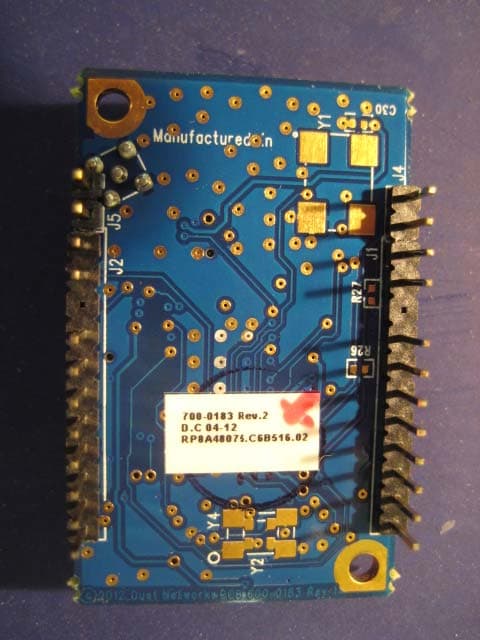
SJC-ETERNA1
Jan 17, 2013802.15.4 Wireless Mesh Mote
Equipment Class
DTS - Digital Transmission System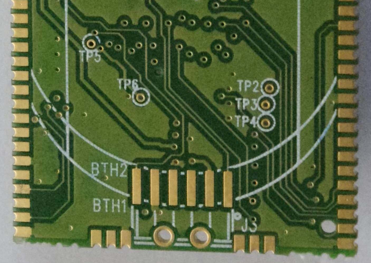
SJC-ETERNA2
Jan 17, 2013802.15.4 Wireless Mesh Mote
Equipment Class
DTS - Digital Transmission System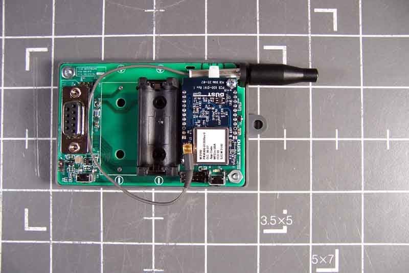
SJC-M2140
Dec 20, 2007Smart Mesh Wireless Mote
Equipment Class
DTS - Digital Transmission System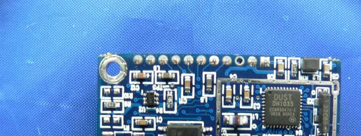
SJC-M1310
Apr 12, 2007900 MHz Mote Frequency Hopping System Module
Equipment Class
DSS - Part 15 Spread Spectrum Transmitter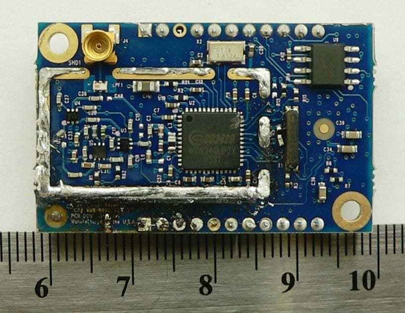
SJC-M2030
Dec 15, 2006SmartMesh M2030 2.4GHz Mote
Equipment Class
DSS - Part 15 Spread Spectrum Transmitter