SLH-BT-1008Bluetooth v2.0 USB Adapter
HL-Tech Corporation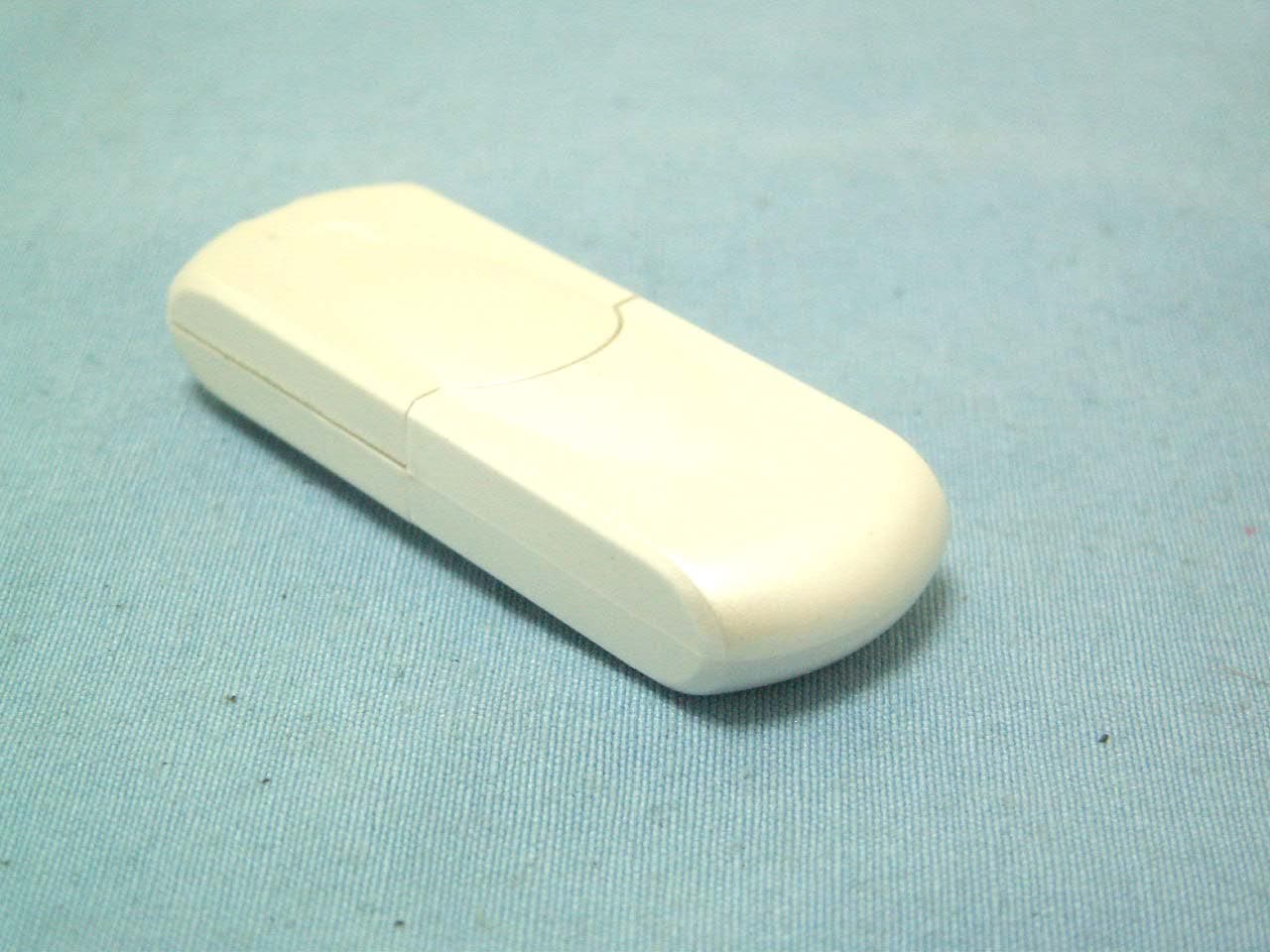
Click to zoom
Application Details
- Equipment Class
- DSS - Part 15 Spread Spectrum Transmitter
- Date of Grant
- Jan 30, 2008
- Application Purpose
- Original Equipment
- Date of Application
- Jan 30, 2008
- Equipment Note
- Bluetooth v2.0 USB Adapter
- Frequency Range
- 2402.00000000 - 2480.00000000
- Company
- HL-Tech Corporation
- Country
- Taiwan
Documents & Files
Document Text
Text extracted from the exhibit documents filed with the FCC. Open a document above to read the original.
Users Manual
BT-1008 BT V2.0 USB Adapter BT-1008 User’s Manual HL-Tech Corporation HL-Tech Corporation 1 BT-1008 BT V2.0 USB Adapter Note: BT-1008 BT V2.0 USB Adapter BT-1008 User’s Manual HL-Tech Corporation HL-Tech Corporation 2 Table of Contents.........................................................2 Introduction...............................................................................................3 1. Configuration and devices......................................................................................3 2. Device properties....................................................................................................4 3. Options....................................................................................................................4 4. Discovery.................................................................................................................4 5. Adding a COM port...................................................................................................5 6. Hardware.................................................................................................................5 7. Adding a device.......................................................................................................6 8. Joining a Personal Area Network............................................................................7 9. Adding a modem.....................................................................................................8 10. Adding a printer....................................................................................................8 11. File Sending and Receiving...................................................................................9 BT-1008 BT V2.0 USB Adapter BT-1008 User’s Manual HL-Tech Corporation HL-Tech Corporation 3 Introduction This article describes how to install and configure a Bluetooth device in Microsoft Windows XP Service Pack 2 (SP2). Note If you install a Bluetooth adapter that is not supported in Windows XP SP2, follow the recommendations that the Bluetooth adapter's manufacturer provides. Installing a Bluetooth adapter that is on the list of supported adapters for Microsoft Windows XP Service Pack 2 (SP2) is only a matter of connecting the device. No configuration is needed before you make the connection. When you install a supported Bluetooth adapter in Windows XP SP2, the adapter becomes active together with the following Microsoft components: • Microsoft Bluetooth Enumerator This component enumerates Bluetooth devices and capabilities. • Bluetooth Device (Personal Area Network) This driver supports Personal Area Network (PAN) connections between devices. • Bluetooth Device (RFCOMM Protocol Transport Driver Interface [TDI]) This component supports dial-up networking (DUN). It also supports other types of connections between devices. • Bluetooth Support Service (BthServ) This service maintains and updates device pairing information. It also performs other functions that are related to Bluetooth features. These components are available in Device Manager after you install a Bluetooth adapter. Other drivers and components are also installed. 1. Configuration and devices You can use the Bluetooth Devices item in Control Panel to configure Bluetooth settings. By using Bluetooth Devices, you can do one or more of the following: • Add or remove a device. • View the properties of a device. • Change your Bluetooth options. • Add a COM port. In Bluetooth Devices, the Devices tab shows all the devices that are currently configured on your computer. By using the Devices tab, you can add a device, remove a device, or view the properties of a device. BT-1008 BT V2.0 USB Adapter BT-1008 User’s Manual HL-Tech Corporation HL-Tech Corporation 4 2. Device properties When you view the properties of a Bluetooth device, you see the following information: • The device type • The hardware address of the Bluetooth adapter • The date and time of the last connection • Information about whether a passkey is used for pairing with the device You can also change the name that Windows uses for the device. This change also affects the name that is used by the Bluetooth File Transfer Wizard and by Add Modem. The Services tab shows information about the services that the device supports. For example, when a Bluetooth phone or a personal digital assistant (PDA) is connected to your computer, this tab may show COM ports that are available for synchronization. This tab may also show Internet dial-up networking connections. You can also select the services that you want to use. 3. Options The Options tab in Bluetooth Devices provides options that control how devices discover and connect to your computer. The main option is Turn discovery on. This option lets devices discover your computer so that you can make a connection. Other options on this tab include the following: • Allow Bluetooth devices to connect to this computer This check box controls whether any devices can connect to your computer. If this check box is cleared, no devices can connect to your computer. • Alert me when a new Bluetooth device wants to connect This option controls whether you receive notification when a device tries to connect to your computer. If this check box is cleared, you do not receive notification. Other options on the Options tab let you turn on or turn off the Bluetooth icon in the notification area and restore default settings. 4. Discovery Typically, your Bluetooth-enabled computer will discover other devices. Therefore, you only have to turn on the Turn discovery on option when your computer acts as a device. For example, you might want to turn on this option when your computer is connected to another computer by a Personal Area Network (PAN). When computers are connected by a PAN, one of the computers must have discovery turned on. By default, discovery is not turned on in Windows XP SP2, because a discoverable Bluetooth device may be less se…
Text truncated - open the document above for the full version.
Cover Letter(s)
HL-Tech Corporation Date 2008/01/15 Compliance Certification Services Certification Division 47173 Benicia Street Fremont, CA 94538, USA To whom it may concern: I, the undersigned, hereby authorize Mr. Kevin Wang /V.P. of Taiwan office of Compliance Engineering Services, Inc., d.b.a. Compliance Certification Services and hereafter referred to as CCS TW, and hereafter referred to as CCS TW, to act on our behalf in all manners relating to application for equipment authorization, including signing of all documents relating to these matters. Any and all acts carried out by Mr. Kevin Wang of CCS TW on our behalf shall have the same effect as acts of our own. I, the undersigned, hereby certify that we are not subject to a denial of federal benefits, that includes FCC benefits, pursuant to Section 5301 of the Anti-Drug Abuse Act of 1988, 21 U.S.C. 853(a). In authorizing CCS as our agent, we still recognize that we are responsible to: a) comply with the relevant provisions of the certification program; b) make all necessary arrangements for the conduct of the evaluation, including provision for examining documentation and access to all areas, records (including internal audit reports) and personnel for the purposes of evaluation (e.g. testing, inspection, assessment, surveillance, reassessment) and resolution of complaints; c) make claims regarding certification only in respect of the scope for which certification has been granted; d) do not use our product certification in such a manner as to bring the Certification Division into disrepute and not make any statement regarding our product certification which the Certification Division may consider misleading or unauthorized; e) upon suspension or cancellation of certification, discontinue use of all advertising matter that contains any reference thereto and return any certification documents as required by the Certification Division; f) use certification only to indicate the products are certified as being in conformity with specified standards; g) endeavor to ensure that no certificate or report nor any part thereof is used in a misleading manner; h) ensure that any reference to our product certification in communication media such as documents, brochures or advertising, complies with the requirements of the Certification Division; i) keep a record of all complaints made known to the us relating to the product’s compliance with requirements of the relevant standard and to make these records available to the Certification Division when requested; j) take appropriate action with respect to such complaints and any deficiencies found in products or services that affect compliance with the requirements for certification; k) document the actions taken. This authorization is valid until further written notice from the applicant. Sincerely Yours, REMARK: 1. This authorization letter will be sent along with your application when filing with the Certification Division. 2. Please follow the format and type it on company letterhead and send original to us. 3. Authorized signature must be in agreement with grantee code contact in FCC database.
External Photos
Compliance Certification Services Inc. Report No.: 80115001 Date of Issue: January 30, 2008 Page 1 Total Page: 4 Rev. 00 EXTERNAL PHOTOGRAPHS OF EUT
ID Label/Location Info
HL-Tech Bluetooth v2.0 USB Adapter Model: FCC ID: SLH-BT-1008
Internal Photos
Compliance Certification Services Inc. Report No.: 80115001 Date of Issue: January 30, 2008 Page 2 Rev.00 INTERNAL PHOTOGRAPHS OF EUT Compliance Certification Services Inc. Report No.: 80115001 Date of Issue: January 30, 2008 Page 3 Rev.00 Compliance Certification Services Inc. Report No.: 80115001 Date of Issue: January 30, 2008 Page 4 Rev.00
Parts List/Tune Up Info
G G a a i i n n F F o o r r c c e e T T e e c c h h n n o o l l o o g g y y C C o o . . , , L L t t d d A A P P P P R R O O V V A A L L S S H H E E E E T T Antenna MODEL NAME AT5020-B2R8HAAT PART NUMBER CUSTOMER GainForce VENDOR MODEL 028221-6858 ACCESSORIES SPECIFICATION SAMPLE DRAWING TEST REPORT APPROVED STATUS ACX Advanced Ceramic X AT5020 Series Multilayer Chip Antenna Features Monolithic SMD with small, low-profile and light-weight type. Wide bandwidth Applications Bluetooth/Wireless LAN/Home RF ISM band 2.4GHz applications Specifications Part Number Frequency Range (MHz) Peak Gain XZ-V Average Gain XZ-V VSWR Impedance AT5020 -B2R8HAA_ 2400 ~ 2500 0 dBi typ. -1 dBi typ. 2 max. 50 Ω Q’ty/Reel (pcs) : 2,000pcs Operating Temperature Range : -40 ~ +85 o C Storage Temperature Range : -40 ~ +85 o C Power Capacity : 3W max. Part Number AT 5020 - B 2R8 HAA i ghfe dc c Type AT : Antenna d Dimensions ( L × W ) 5.0× 2.0 mm e Material Code B f Frequency Range 2R8=2800MHz g Specification Code HAA h Packaging T: Tape & Reel B: Bulk i Soldering =lead-containing /LF=lead-free Terminal Configuration No. Terminal Name No. Terminal Name c Feeding Point d NC d c ACX Advanced Ceramic X Dimensions and Recommended PC Board Pattern Unit : mm a W T L Mark L W T a Dimensions 5.00.2 2.00.2 1.10.2 0.50.3 (a) Without Matching Circuits 1.0 * 3.9 5.9 1.0 * * 1.8 1.0 (b) With Matching Circuits * 3.9 8.9 1.8 4.0 1.0 1.0 * * *Line width should be designed to match 50Ω characteristic impedance, depending on PCB material and thickness. ACX Advanced Ceramic X Typical Electrical Characteristics (T=25 o C) Test Board Antenna No Ground Ground 18mm 18mm 30mm 50Ω Feed Line 9.6mm Return Loss (a) Without Matching Circuits (b) With Matching Circuits ACX Radiation Patterns Advanced Ceramic X 180 o 270 o 0 o 90 o X Z Y XY-cut scanning direction 180 270 o 0 o 90 o X Z Y XZ-cut scanning direction 180 270 0 o 90 o X Z Y YZ-cut scanning direction XY cut @2.45GHz Vertical Horizontal XY cut @2.45GHz Vertical Horizontal XZ cut @2.45GHz Vertical Horizontal YZ-V/YZ-H XZ-V/XZ-H XY-V/XY-H Advanced Ceramic X Corp. 16 Tzu Chiang Road, Hsinchu Industrial District Hsinchu Hsien 303, Taiwan TEL:886-3-5987008 FAX:886-3-5987001 E-mail: [email protected] http://www.acxc.com.tw ACX Adv anced Ceram ic X Item Requirements Procedure Solderability 1. No apparent damage 2. More than 75% of the terminal electrode shall be covered with new solder 1. Preheat: 120± 5 o C 2. Solder: 230± 5 o C for 5± 1 sec Thermal shock (Temperature Cycle) 1. No apparent damage 2. Fulfill the electrical specification after test 1. One cycle/ step 1: 85 ± 5 o C for 20sec step 2: -40 ± 3 o C for 20sec 2. Cycle time: 30min 3. No. of cycles: 100 4. Recovery: 1-2hrs Heat Resistance 1. No apparent damage 2. Fulfill the electrical specification after test 1. Temperature: 85± 2 o C 2. Duration: 24±2hrs 3. Recovery: 1-2hrs Low Temperature Resistance 1. No apparent damage 2. Fulfill the electrical specification after test 1. Temperature: -40 o ± 5 o C 2. Duration: 24 ±2hrs 3. Recovery: 1-2hrs Humidity Resistance 1. No apparent damage 2. Fulfill the electrical specification after test 1. Temperature: 85± 2 o C 2. Humidity: 80% ~ 85% RH 3. Duration: 1000±48hrs 4. Recovery: 1-2hrs Soldering strength (Push strength) 1. 9.8N minimum 1. Solder specimen onto test jig. 2. Apply push force at 0.5mm/s until electrode pads are peeled off or ceramic are broken. Pushing force is applied to longitude direction Deflection (Bending) 1. No apparent damage 2. Fulfill the electrical specification 1. Solder specimen onto test jig (FR4, 0.8mm) using the recommend soldering profile. 2. Apply a bending force of 2mm deflection ` Drop Shock 1. No apparent damage 1. Dropped onto hard wood from height of 50 cm for 3 times ; each x,y and z direction except terminal direction Mechanical & Environmental Characteristics R230 Pressure Rod 90mm ACX Adv anced Ceram ic X Typical Soldering Profile Typical Soldering Profile for Lead-free Process Flow Soldering : Reflow Soldering : T e m p erature ( o C) 20s. 230 o C 180 o C 260C 5s, max. Time (s.) 60s, min. Pre-heating 30s. 230 o C 180 o C 250 o C 10s, max. Time (s.) 60s, min. Pre-heating T e m p erature ( o C) The sample must be pre-heated before soldering .The temperature difference between preheating and soldering must be within 150 . Notes The contents of this data sheet are subject to change without notice. Please confirm the specifications and delivery conditions when placing your order. ACX Advanced Ceramic X Taping Specifications Tape Dimensions (Unit: mm) φ1.55 +0.05 A’ t D 7.5 ± 0.1 1.75 ± 0.1 C T A B 16± 0.2 A A’ B C D t T 4.0 0.1 4.0 0.1 1.9 0.1 3.5 0.1 2.0 0.1 0.20 0.05 Max. 1.4 4.0 0.1 4.0 0.1 2.4 0.1 5.5 0.1 2.0 0.1 0.20 0.05 Max. 1.4 7020 4.0 0.1 4.0 0.1 2.4 0.1 7.3 0.1 2.0 0.1 0.22 0.05 Max. 1.55 7635 8.0 0.1 4.0 0.1 3.75 0.1 7.85 0.1 2.0 0.1 0.30 0.05 Max. 1.40 8516 4.0 0.1 4.0 0.1 1.85 0.1 8.70 0.1 2.0 0.1 0.25 0.05 Max. 1.40 9520 4.0 0.1 4.0 0.1 2.3 0.1 9.7 0.1 2.0 0.1 0.22 0.05 Max. 1.45 R130 8.0 0.1 4.0 0.1 3.35 0.1 10.35 0.1 2.0 0.1 0.25 0.05 Max. 1.40 Typ e 3216 5020 Quantity Type 3216 5020 7020 7635 8516 9520 R130 Quantity /per reel 3,000pcs 2,000 1,000 pcs 1,000 pcs 1000pcs 1,000 pcs 1,000 pcs Reel Dimensions (Unit: mm) 178 ± 2.0 60 ± 0.5 1.4 Label: Customer’s Name, ACX P/N, Q’ty, Date, ACX Corp. D:13.0 ± 0.3 2.0 ± 0.5 D:21.8 ± 0.8 Label 19.5 16.7 ± 0.3 Leader and Trailer Tape (Plastic material) Trailer End Trailer (80mm min.) Cover Tape Only 60mm min. Leader End Empty Compartments with Cover Tape (80mm min.) Peel-off Force Peelin g Direction Top Cover Tape Carrier Ta pe <10 0 Peel-off force should be in the range of 0.1 – 0.6 N at a peel-off speed of 30010 mm/min . ACX Adv anced Ceramic X Storage Conditions (1) Temperature: 15 ~35, relative humidity (RH): 45~75%. (2) Non-corrosive environment (3) Products should be used within six months of receipt. Notes The contents of this data sheet are subject to change without notice. …
Text truncated - open the document above for the full version.
Test Report
Compliance Certification Services Inc. Report No.: 80115001-RP1 FCC ID: SLH-BT-1008Date of Issue: January 30, 2008 Note: This report shall not be reproduced except in full, without the written approval of Compliance Certification Services Inc. This document may be altered or revised by Compliance Certification Services Inc. personnel only, and shall be noted in the revision section of the document. Page 1 Total Page: 71 Rev. 00 FCC 47 CFR PART 15 SUBPART C TEST REPORT For Bluetooth v2.0 USB Adapter Model: BT-1008 Trade Name: HL-Tech Issued to HL-Tech Corporation. 2F-1, No. 13, Lane 120, Sec. 1, Nei Hu Rd., Taipei, Taiwan 114, R.O.C. Issued by Compliance Certification Services Inc. No. 81-1, Lane 210, Bade Rd. 2, Luchu Hsiang, Taoyuan Hsien, (338) Taiwan, R.O.C. http://www.ccsemc.com.tw [email protected] Compliance Certification Services Inc. Report No.: 80115001-RP1 FCC ID: SLH-BT-1008 Date of Issue: January 30, 2008 TABLE OF CONTENTS 1. TEST RESULT CERTIFICATION.................................................................................................3 2. EUT DESCRIPTION........................................................................................................................4 3. TEST METHODOLOGY.................................................................................................................5 3.1 EUT CONFIGURATION.....................................................................................................................5 3.2 EUT EXERCISE.................................................................................................................................5 3.3 GENERAL TEST PROCEDURES..........................................................................................................5 3.4 FCC PART 15.205 RESTRICTED BANDS OF OPERATIONS.....................................................6 3.5 DESCRIPTION OF TEST MODES........................................................................................................7 4. INSTRUMENT CALIBRATION.....................................................................................................8 4.1 MEASURING INSTRUMENT CALIBRATION...................................................................................8 4.2 MEASUREMENT EQUIPMENT USED......................................................................................8 5. FACILITIES AND ACCREDITATIONS.......................................................................................9 5.1 FACILITIES ......................................................................................................................................9 5.2 EQUIPMENT.....................................................................................................................................9 5.3 TABLE OF ACCREDITATIONS AND LISTINGS..................................................................................10 6. SETUP OF EQUIPMENT UNDER TEST....................................................................................11 6.1 SETUP CONFIGURATION OF EUT....................................................................................................11 6.2 SUPPORT EQUIPMENT............................................................................................................11 7. FCC PART 15.247 REQUIREMENTS..........................................................................................12 7.1 PEAK POWER.................................................................................................................................12 7.2 A VERAGE POWER.........................................................................................................................14 7.3 BAND EDGES MEASUREMENT.............................................................................................15 7.4 PEAK POWER SPECTRAL DENSITY.................................................................................................24 7.5 FREQUENCY SEPARATION....................................................................................................30 7.6 NUMBER OF HOPPING FREQUENCY...................................................................................33 7.7 TIME OF OCCUPANCY (DWELL TIME)................................................................................36 7.8 SPURIO US EMISSIONS.............................................................................................................49 7.9 POWERLINE CONDUCTED EMISSIONS............................................................................................64 APPENDIX I RADIO FREQUENCY EXPOSURE............................................................................67 APPENDIX II PHOTOGRAPHS OF TEST SETUP..........................................................................69 Page 2 Rev. 00 Compliance Certification Services Inc. Report No.: 80115001-RP1 FCC ID: SLH-BT-1008 Date of Issue: January 30, 2008 1. TEST RESULT CERTIFICATION Applicant: HL-Tech Corporation. 2F-1, No. 13, Lane 120, Sec. 1, Nei Hu Rd., Taipei, Taiwan 114, R.O.C. Equipment Under Test: Bluetooth v2.0 USB Adapter Trade Name: HL-Tech Model: BT-1008 Date of Test: January 16 ~ 17, 2008 APPLICABLE STANDARDS STANDARD TEST RESULT FCC 47 CFR Part 15 Subpart C No non-compliance noted We hereby certify that: The above equipment was tested by Compliance Certification Services Inc. The test data, data evaluation, test procedures, and equipment configurations shown in this report were made in accordance with the procedures given in ANSI C63.4: 2003 and the energy emitted by the sample EUT tested as described in this report is in compliance with the requirements of FCC Rules Part 15.207, 15.209, 15.247. The test results of this report relate only to the tested sample EUT identified in this report. Approved by: Reviewed by: Rex Lai Amanda Wu Section Manager Section Manager Compliance Certification Services Inc. Compliance Certification Services Inc. Page 3 Rev. 00 Compl…
Text truncated - open the document above for the full version.
Test Setup Photos
Compliance Certification Services Inc. Report No.: 80115001-RP1 FCC ID: SLH-BT-1008 Date of Issue: January 30, 2008 APPENDIX II PHOTOGRAPHS OF TEST SETUP CONDUCTED EMISSION SETUP PHOTO Page 69 Rev. 00 Compliance Certification Services Inc. Report No.: 80115001-RP1 FCC ID: SLH-BT-1008 Date of Issue: January 30, 2008 RADIATED EMISSION SETUP PHOTOS Page 70 Rev. 00 Compliance Certification Services Inc. Report No.: 80115001-RP1 FCC ID: SLH-BT-1008 Date of Issue: January 30, 2008 POWERLINE CONDUCTED EMISSIONS SETUP PHOTOS Page 71 Rev. 00
Contact Information
Applicant
Dio Lin
Test Firm
Compliance Certification Services Inc.Winnie Chen
Technical Specifications
| # | Rule Parts | Frequency Range | Power Output |
|---|---|---|---|
| 1 | 15C | 2.40 GHz - 2.48 GHz | 1.00 mW |
Other Applications from HL-Tech Corporation
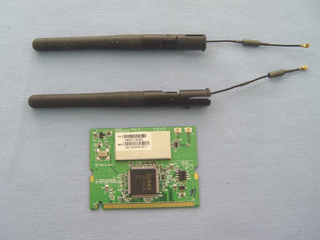
SLH-WL-3002B
Nov 19, 2007WLAN 802.11b/g mini PCI Card
Equipment Class
DTS - Digital Transmission System
SLH-WL-8005
Oct 31, 2007Wireless Access Point (AP)
Equipment Class
DTS - Digital Transmission System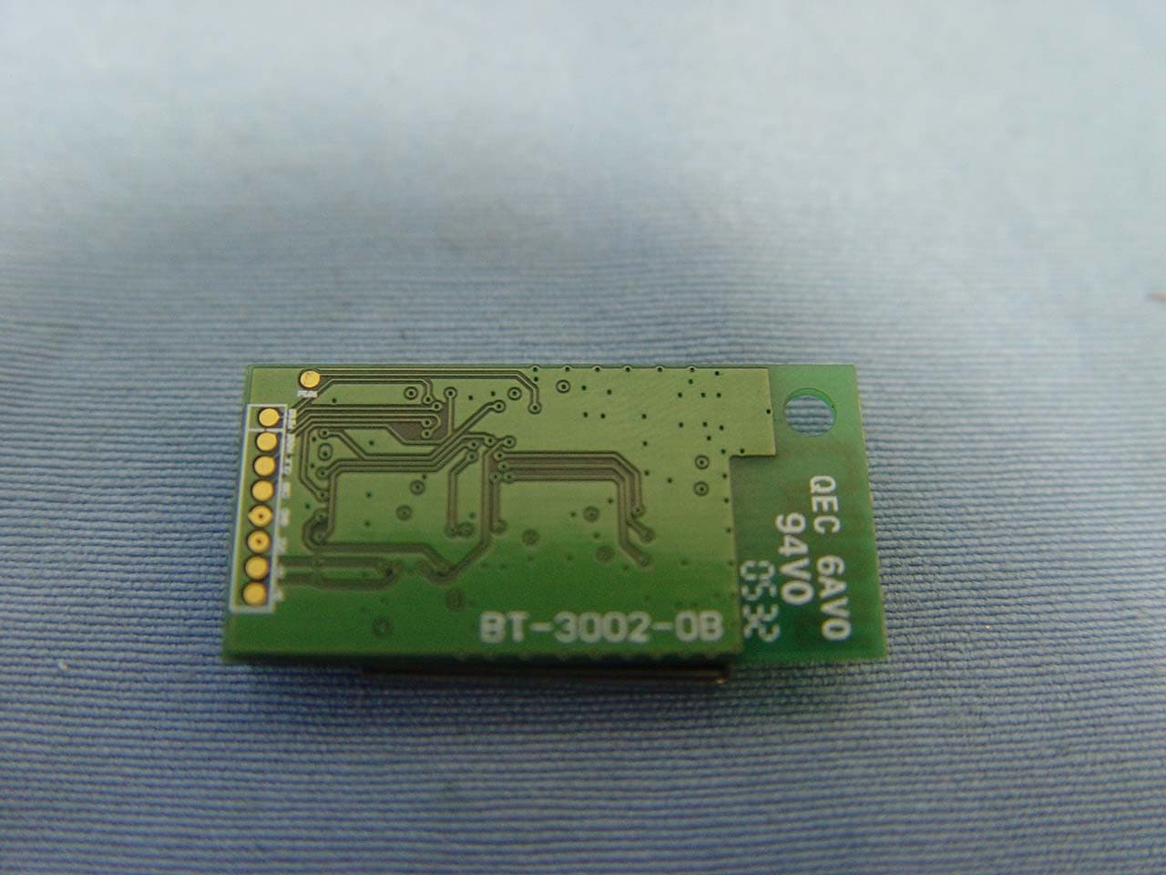
SLH-BT-3005
Feb 16, 2006BT V2.0 USB Module
Equipment Class
DSS - Part 15 Spread Spectrum Transmitter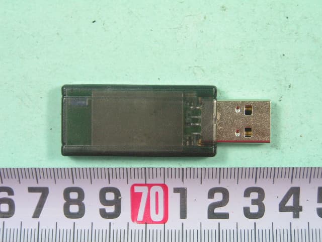
SLH-BT-1005
Nov 03, 2005BT V2.0 USB Dongle
Equipment Class
DSS - Part 15 Spread Spectrum Transmitter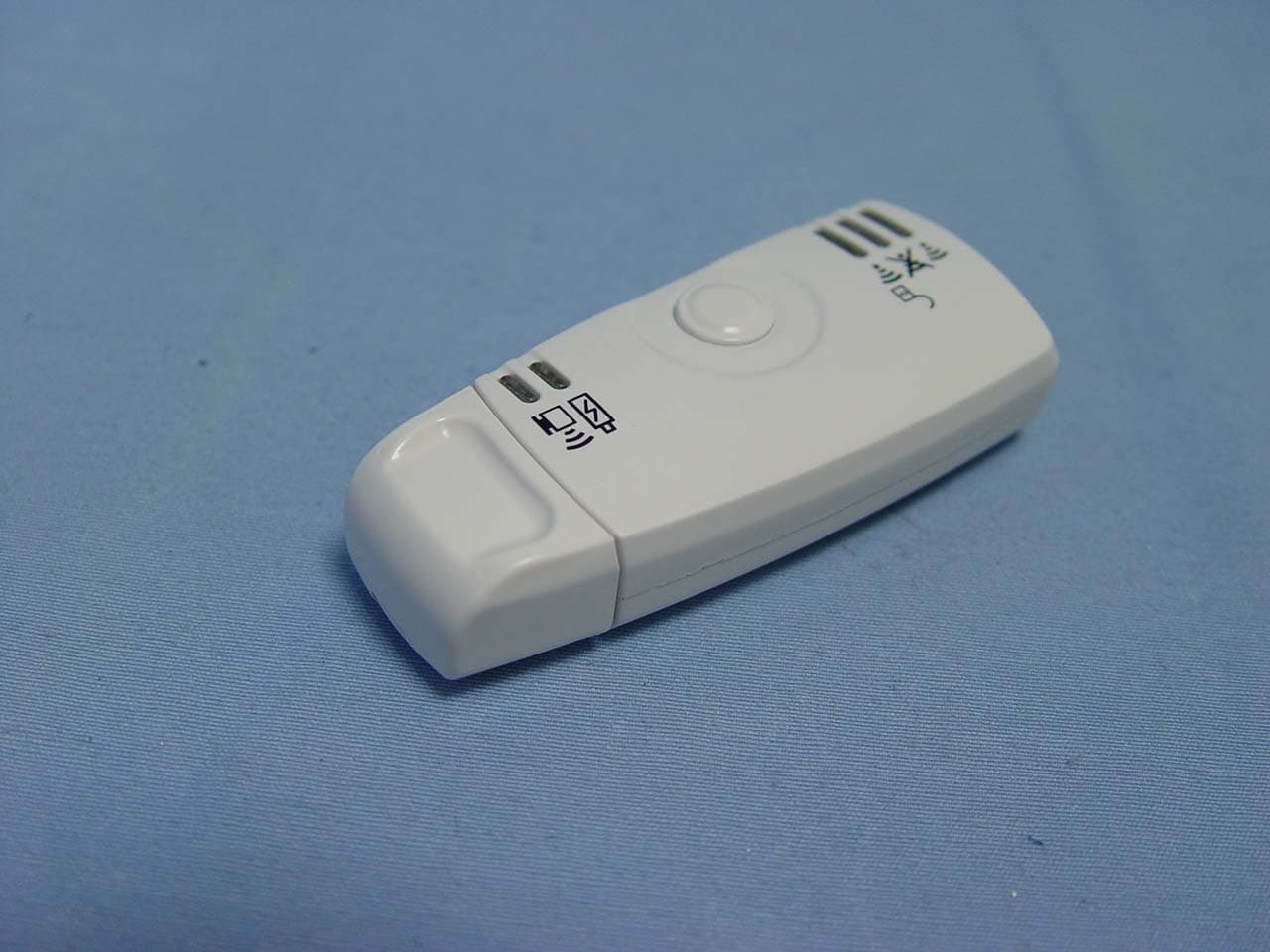
SLH-WL-1003
Sep 21, 2005WiFi Finder
Equipment Class
DTS - Digital Transmission System