SMJU200Network Terminal (USB Type)
NComputing Co., Ltd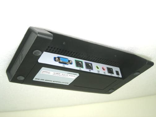
Click to zoom
Application Details
- Equipment Class
- JBP - Part 15 Class B Computing Device Peripheral
- Date of Grant
- Oct 24, 2004
- Application Purpose
- Original Equipment
- Date of Application
- Oct 24, 2004
- Equipment Note
- Network Terminal (USB Type)
- Company
- NComputing Co., Ltd
- Country
- South Korea
Documents & Files
Document Text
Text extracted from the exhibit documents filed with the FCC. Open a document above to read the original.
Users Manual
1 PC Expanion User’s Manual (U200, U2000 Series) © Copyright by Ncomputing Co. Ltd. 2004 . - Illegal copying of this software, hardware and this documentation is prohibited by law. All other brand- and product names are trademarks of registered trademarks of the respective owners. 2 Safety Instructions - Do not use this system on an unstable cart, stand or table. The product may fall, causing serious damage to the product. - Slots and openings in the cabinet and the back have been provided for ventilation. To ensure reliable operation of your computer, and to protect it from overheating, do not block or cover these openings. - Never push objects of any kind into the system through the cabinet openings. Objects may touch dangerous voltage points or short out parts that could result in a fire or electrical shock. Never spill liquid of any kind on the product. - This computer should only be connected to the adapter comes with your system. If you want to use other adapter, consult your dealer. - Do not allow anything to rest on the power cord. Do not locate this product where people will walk on the cord. - Unplug your system form the main electrical power outlet before cleaning. Do not use liquid cleaners or aerosol cleaners. Use a damp cloth for cleaning. - Do not use this system near water. - Your adapter plug will only fit into a grounding-type power outlet. This is a safety feature. If you are unable to insert or replace your obsolete outlet, contact your electrician to replace your obsolete outlet. Do not defeat the purpose of the grounding-type plug. - To avoid generating an electric shock, be sure to plug the power cord into the system before plugging it into the wall socket. - For protection of your system and other devices during a lightning storm, or when it is left unattended and unused for long periods of time, unplug the computer and other devices form the wall outlet and disconnect the cable form system. This will prevent damage to the system and other devices due to lighting and power line surges. Warning 3 FCC Information to Use Note : This equipment has been tested and found to comply with the limit for a Class B digital device, pursuant 15 of the FCC Rules. These limits are designed to provide reasonable protection against harmful interference in a residential installation. This equipment generates, uses, and can radiate radio frequency energy and, if not installed and used in accordance with the instructions. May cause harmful interference to radio communications. However, there is no guarantee that interference will not occur in a particular installation. IF this equipment does cause harmful interference to radio or television reception, which can be determined by turning the equipment off nad on, the user is encourage to try to correct the interference by one or the following measures: - Reorient or relocate the receiving antenna. - Increase the separation between the equipment and receiver - Connect the equipment into an outlet on a circuit different from that to which the receiver is connected - Consult the dealer or an experience radio TV technician for help Change or modification not expressly approved by the party responsible for Compliance could void the user’s authority to operate the equipment 4 5 Contents overview and Hardware installation of PC Expanion 1. Introductions - Configuration of PC Expanion 2. Overview - Front - Rear I Installation device driver and NCU-2000/XP Software 1. Connecting PC Expanion to the Computer 2. Installing the Driver in Windows XP 3. Installing NCU-2000/XP Software Unpacking the Box on PC Expanion PC Expanion Specification 6 Overview & H/W installation of PC Expanion 1. Introductions PC Expanion is the world’s first terminal unit that does not require a CPU, hard-driver, or CD-ROM yet executes as if it’s an ordinary PC with hardware, With PC Expanions exclusive UTMA(Ultra Thin Multi Access) technology. PC Expanion is executed under windows and USB2.0. Also, PC Expanion have the VGA solution under USB2.0. Configuration 1) I/O PORT - Video Out: D-SUB 15 Pin RGB - Keyboard Port - Mouse Port - Sound Out/MIC In - One USB 2.0 Port : One is “B” Type 2) System Requirements - Support USB 2.0 - Windows 2000 Professional Edition - Windows XP Home & Professional Edition 3) Package Contents - PC Expanion system - Driver CD / Manual 4) System Requirement Host PC z Pentium4 2.0G / HDD 60GB / 512MB Memory or higher 7 2. Overview 1. Front ① Power button Turn on/off PC Expanion. ② Power Indicators Light up when the system on. ③ Power Indicators 2 Light up when the system on. ④ Keyboard operation Indicators Blinks when Keyboard operation ⑤ Mouse operation Indicators Blinks when Mouse operation ⑥ USB Hub Indicators Light up when PC Expanion USB ready to use. 1 4 3 5 2 8 2. Rear ① Power Inlet (DC-IN) Jack Connection for ac adapter power cord ② PC Connect USB 2.0 Port for connect PC ③ MIC Jack Connection for Mic Jack ④ Speaker Jack Connection for stereo Speaker jack ⑤ Keyboard Connection for PS/2 type Keyboard ⑥ Mouse Connection for PS/2 type Mouse ⑦ VGA Connection for external monitor 5 2 3 4 6 1 7 9 Installation device driver and NCU-2000/XP Software PC Expanion can be installed in the operating systems Windows XP and Windows 2000. 1. Connecting PC Expanion to the Computer 1. Switch on your computer 2. Remove the enclosed USB cable from the package. The USB cable hast two different plugs one that is flat and square (known as the Series-B connector) and one that is rectangular ( known as the Series-A connector). 3. Insert the flat "series A" plug in your computer s USB port. 4. Then insert the square connector into the USB socket of PC Expanion. Now the software components of PC Expanion can be installed. Read the following sections for instructions. 10 2. Installing the Driver in Windows XP Once you have connected PC Expanion to the computer, press the button from the PC- Expanion for Power On, now the Plug & Play mechanism of Windows XP recognize the…
Text truncated - open the document above for the full version.
Block Diagram
PC PC Expanion Expanion Block Diagram Block Diagram Video Chipset SIS 315E NEC D720112 USB 2.0 Hub CM108 USB Audio Memory(8MB) EM638325 NetChipNET2280 PCI USB Keyboard Conn. MOUSE Conn. USB B type Connector Audio Jack Conn. 1.0 Version NComputing Company U200 Project DATA ADDR TXD[3:0] KDATA/KCLK MDATA/MCLK VIDEO_OUT Cypress CPLD MIC Jack Conn. AD CMD DATA DATA Video Connector 12MHz 8 MHz CLK66 MHz CLK33 MHz 30MHz
External Photos
Appendix C. External Photographs E04.1011.FCC.542N / Page C1 of C1 Head Office: # 371-51 Kasan-Dong, Keumcheon-ku, Seoul, 153-023, Korea / Tel : 82-2-858-0786, Fax : 82-858-0788 EMC Lab: #584 Sangwhal-ri, Kanam-myon, Yoju-kun, Kyounggi-do, 469-885, Korea /Tel:82-31-885-0072, Fax:82-31-885-0074 Form NO: ETL(E)004A4001201-0 Front View of EUT Rear View of EUT
ID Label/Location Info
Appendix A. FCC ID Label and Location E04.1011.FCC.542N / Page A1 of A1 Head Office: # 371-51 Kasan-Dong, Keumcheon-ku, Seoul, 153-023, Korea / Tel : 82-2-858-0786, Fax : 82-858-0788 EMC Lab: #584 Sangwhal-ri, Kanam-myon, Yoju-kun, Kyounggi-do, 469-885, Korea /Tel: 82-31-885-0072, Fax:82-31-885-0074 Form NO: ETL(E)004A4001201-0 Product label sample with FCC label information Following is a sample copy of the label that will be placed on the rear cabinet of the product. The FCC ID label and compliance statement are marked in the product label. Label Location The label shown shall be permanently affixed at a conspicuous location on the device and be readily visible to the user at the time purchase.(Labeling requirements per 2.925) Ncomputing Co., Ltd. Network Terminal(USB Type) FCC ID : SMJU200 Model No : U200 Power : AC/DC Adapter : Input AC110 V ~ 220V, 60Hz 0.3A Output DC 5V, 2.0A Serial No : N/A This device complies with Part 15 of the FCC Rules. Operation is Subject to the following two conditions: (1) this device may not Cause harmful interference, and(2) this device must accept any Interference received, including interference that may cause undesired Operation. Made in Korea Label here
Internal Photos
Appendix D. Internal Photographs E04.1011.FCC.542N / Page D1 of D1 Head Office: # 371-51 Kasan-Dong, Keumcheon-ku, Seoul, 153-023, Korea / Tel : 82-2-858-0786, Fax : 82-858-0788 EMC Lab: #584 Sangwhal-ri, Kanam-myon, Yoju-kun, Kyounggi-do, 469-885, Korea /Tel:82-31-885-0072, Fax:82-31-885-0074 Form NO: ETL(E)004A4001201-0 View of Inside Appendix D. Internal Photographs E04.1011.FCC.542N / Page D2 of D2 Head Office: # 371-51 Kasan-Dong, Keumcheon-ku, Seoul, 153-023, Korea / Tel : 82-2-858-0786, Fax : 82-858-0788 EMC Lab: #584 Sangwhal-ri, Kanam-myon, Yoju-kun, Kyounggi-do, 469-885, Korea /Tel:82-31-885-0072, Fax:82-31-885-0074 Form NO: ETL(E)004A4001201-0 Component side view of Main board Appendix D. Internal Photographs E04.1011.FCC.542N / Page D3 of D3 Head Office: # 371-51 Kasan-Dong, Keumcheon-ku, Seoul, 153-023, Korea / Tel : 82-2-858-0786, Fax : 82-858-0788 EMC Lab: #584 Sangwhal-ri, Kanam-myon, Yoju-kun, Kyounggi-do, 469-885, Korea /Tel:82-31-885-0072, Fax:82-31-885-0074 Form NO: ETL(E)004A4001201-0 Solder side view of Main board Appendix D. Internal Photographs E04.1011.FCC.542N / Page D4 of D4 Head Office: # 371-51 Kasan-Dong, Keumcheon-ku, Seoul, 153-023, Korea / Tel : 82-2-858-0786, Fax : 82-858-0788 EMC Lab: #584 Sangwhal-ri, Kanam-myon, Yoju-kun, Kyounggi-do, 469-885, Korea /Tel:82-31-885-0072, Fax:82-31-885-0074 Form NO: ETL(E)004A4001201-0 Component side view of Main board Component side view of USB and VGA board Appendix D. Internal Photographs E04.1011.FCC.542N / Page D5 of D5 Head Office: # 371-51 Kasan-Dong, Keumcheon-ku, Seoul, 153-023, Korea / Tel : 82-2-858-0786, Fax : 82-858-0788 EMC Lab: #584 Sangwhal-ri, Kanam-myon, Yoju-kun, Kyounggi-do, 469-885, Korea /Tel:82-31-885-0072, Fax:82-31-885-0074 Form NO: ETL(E)004A4001201-0 Rear side view of USB and VGA board Component side view of USB and VGA board Appendix D. Internal Photographs E04.1011.FCC.542N / Page D6 of D6 Head Office: # 371-51 Kasan-Dong, Keumcheon-ku, Seoul, 153-023, Korea / Tel : 82-2-858-0786, Fax : 82-858-0788 EMC Lab: #584 Sangwhal-ri, Kanam-myon, Yoju-kun, Kyounggi-do, 469-885, Korea /Tel:82-31-885-0072, Fax:82-31-885-0074 Form NO: ETL(E)004A4001201-0 Component side view of SW board Solder side view of SW board Appendix D. Internal Photographs E04.1011.FCC.542N / Page D7 of D7 Head Office: # 371-51 Kasan-Dong, Keumcheon-ku, Seoul, 153-023, Korea / Tel : 82-2-858-0786, Fax : 82-858-0788 EMC Lab: #584 Sangwhal-ri, Kanam-myon, Yoju-kun, Kyounggi-do, 469-885, Korea /Tel:82-31-885-0072, Fax:82-31-885-0074 Form NO: ETL(E)004A4001201-0 Component side view of LED board Solder side view of LED board Appendix D. Internal Photographs E04.1011.FCC.542N / Page D8 of D8 Head Office: # 371-51 Kasan-Dong, Keumcheon-ku, Seoul, 153-023, Korea / Tel : 82-2-858-0786, Fax : 82-858-0788 EMC Lab: #584 Sangwhal-ri, Kanam-myon, Yoju-kun, Kyounggi-do, 469-885, Korea /Tel:82-31-885-0072, Fax:82-31-885-0074 Form NO: ETL(E)004A4001201-0 Side view of Adapter Side view of label Appendix D. Internal Photographs E04.1011.FCC.542N / Page D9 of D9 Head Office: # 371-51 Kasan-Dong, Keumcheon-ku, Seoul, 153-023, Korea / Tel : 82-2-858-0786, Fax : 82-858-0788 EMC Lab: #584 Sangwhal-ri, Kanam-myon, Yoju-kun, Kyounggi-do, 469-885, Korea /Tel:82-31-885-0072, Fax:82-31-885-0074 Form NO: ETL(E)004A4001201-0 Component side view of power Solder side view of power Appendix D. Internal Photographs E04.1011.FCC.542N / Page D10 of D10 Head Office: # 371-51 Kasan-Dong, Keumcheon-ku, Seoul, 153-023, Korea / Tel : 82-2-858-0786, Fax : 82-858-0788 EMC Lab: #584 Sangwhal-ri, Kanam-myon, Yoju-kun, Kyounggi-do, 469-885, Korea /Tel:82-31-885-0072, Fax:82-31-885-0074 Form NO: ETL(E)004A4001201-0 Top main cover Bottom main cover Appendix D. Internal Photographs E04.1011.FCC.542N / Page D11 of D11 Head Office: # 371-51 Kasan-Dong, Keumcheon-ku, Seoul, 153-023, Korea / Tel : 82-2-858-0786, Fax : 82-858-0788 EMC Lab: #584 Sangwhal-ri, Kanam-myon, Yoju-kun, Kyounggi-do, 469-885, Korea /Tel:82-31-885-0072, Fax:82-31-885-0074 Form NO: ETL(E)004A4001201-0 Top DC adapter cover Bottom DC adapter cover
Operational Description
FCC TEST REPORT E04.1011.FCC.542N / Page 4 of 15 Head Office : # 371-51 Kasan-Dong, Keumcheon-ku, Seoul, 153-023, Korea /Tel : 82-2-858-0786, Fax : 82-2-858-0788 EMC Lab : #584 Sangwhal-ri, Kanam-myon, Yoju-kun, Kyounggi-do, 469-885, Korea /Tel : 82-31-885-0072, Fax : 82-31-885-0074 2.1 General Remarks U200 is basic model and it was tested. U2000 is same model. difference is model name only. 2.2 Equipment Description The Equipment Under Test (EUT) is the NComputing Co., Ltd. Network Terminal, U200 2.3 General Specification l Chassis Type : Plastic l I/O PORT 1) I/O PORT - Video Out : D-SUB 15 Pin RGB - Keyboard Port - Mouse Port - Sound Out/MIC In - One USB 2.0 Port : One is “B” Type 2) System Requirements - Support USB 2.0 - Windows 2000 Professional Edition - Windows XP Home & Professional Edition 3) Package Contents - PC Expanion system - Driver CD / Manual 4) System Requirement Host PC - Pentium4 2.0G / HDD 60GB / 512MB Memory or higher
Test Setup Photos
Appendix B. Test Setup Photographs E04.1011.FCC.542N / Page B1 of B1 Head Office: # 371-51 Kasan-Dong, Keumcheon-ku, Seoul, 153-023, Korea / Tel : 82-2-858-0786, Fax : 82-858-0788 EMC Lab: #584 Sangwhal-ri, Kanam-myon, Yoju-kun, Kyounggi-do, 469-885, Korea /Tel:82-31-885-0072, Fax:82-31-885-0074 Form NO: ETL(E)004A4001201-0 Conducted Emission Test Setup Appendix B. Test Setup Photographs E04.1011.FCC.542N / Page B2 of B2 Head Office: # 371-51 Kasan-Dong, Keumcheon-ku, Seoul, 153-023, Korea / Tel : 82-2-858-0786, Fax : 82-858-0788 EMC Lab: #584 Sangwhal-ri, Kanam-myon, Yoju-kun, Kyounggi-do, 469-885, Korea /Tel:82-31-885-0072, Fax:82-31-885-0074 Form NO: ETL(E)004A4001201-0 Radiated Emission Test Setup
Contact Information
Applicant
Chang Yu(engineering director)
Test Firm
E-RAE Testing LaboratoryYo Han Park
Technical Specifications
| # | Rule Parts | Frequency Range | Power Output |
|---|---|---|---|
| 1 | 15B | - | - |
Other Applications from NComputing Co., Ltd
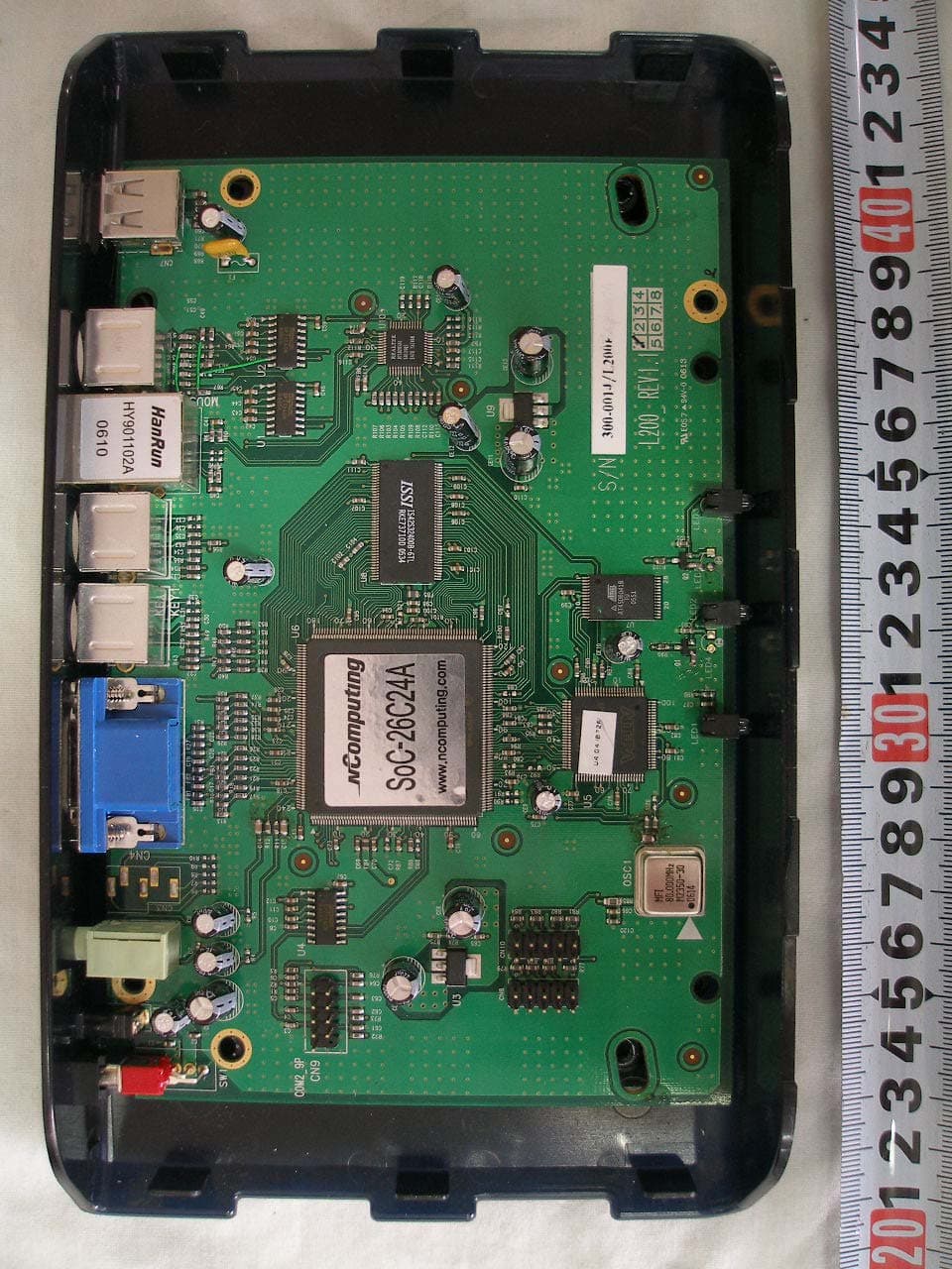
SMJL200
Jun 15, 2006MULTI-USER NETWORK TERMINAL
Equipment Class
JBP - Part 15 Class B Computing Device Peripheral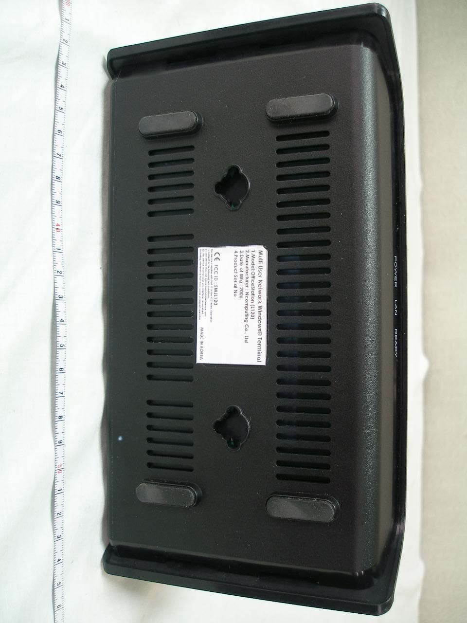
SMJL120
Apr 17, 2006MULTI-USER NETWORK TERMINAL
Equipment Class
JBP - Part 15 Class B Computing Device Peripheral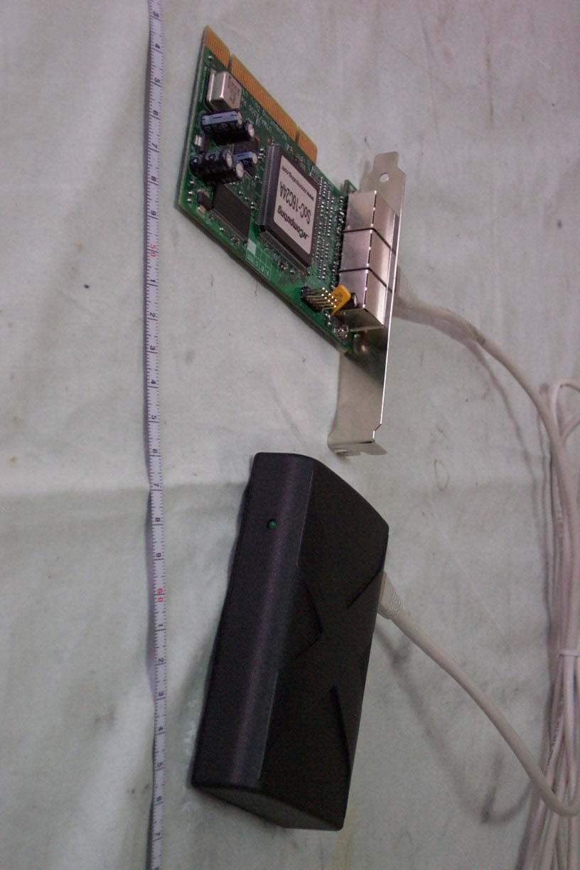
SMJX300
Jan 01, 2006Multi-user Networking Card
Equipment Class
JBP - Part 15 Class B Computing Device Peripheral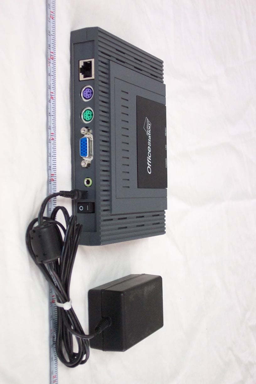
SMJL110
Apr 20, 2005OFFICESTATION
Equipment Class
JBP - Part 15 Class B Computing Device Peripheral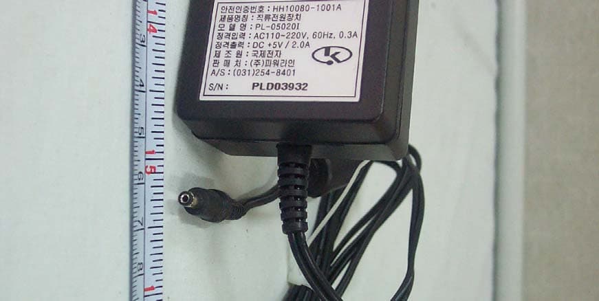
SMJL100
Nov 04, 2004OFFICESTATION
Equipment Class
JBP - Part 15 Class B Computing Device Peripheral