SOM-201549BT Headset
VXI Corporation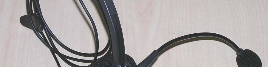
Click to zoom
Application Details
- Equipment Class
- DSS - Part 15 Spread Spectrum Transmitter
- Date of Grant
- Nov 21, 2004
- Application Purpose
- Original Equipment
- Date of Application
- Nov 21, 2004
- Equipment Note
- BT Headset
- Frequency Range
- 2402.00000000 - 2480.00000000
- Company
- VXI Corporation
- Country
- United States
Documents & Files
Document Text
Text extracted from the exhibit documents filed with the FCC. Open a document above to read the original.
Users Manual
Blue Parrott B100 Wireless Headset User Guide TABLE OF CONTENTS Box Contents 3 Basic Safety Instructions 4 Product Features 5 Glossary Of Terms 7 Operation Summary 7 Compatibility Information 7 Maximizing Range 8 Installation 9 Charging The Headset 11 Battery Information 11 Talk Time / Standby Time 11 Headset Adjustments / Microphone Positioning 13 Basic Operations Make A Call / End A Call 14 Answer A Call / End A Call 15 Adjust Receive Volume 15 Microphone Mute On / Off 15 Switch From Headset To Handset 16 Switch From Handset To Headset 16 Call Waiting / Three-way conferencing 16 Pairing Pair The Blue Parrott Base With A Different Bluetooth Headset 17 Pair The Blue Parrott Headset With A Bluetooth Cellular Phone 18 Visual And Audio Indicators Explained 19 FAQ’s (Frequently Asked Questions) 20 Legal 21 Box Contents Blue Parrott B100 Base Blue Parrott B100 Headset Box Contents AC adapter Line cord Quick start card User manual 2 cord wraps Basic Safety Instructions Do not immerse the Blue Parrott B100 in water. Plastic bags and small parts may cause choking if ingested. Keep them away from children and pets. The battery is nickel metal hydride, after replacing; dispose of according to local waste disposal regulations. Use only the power cord included with this product. Avoid using during lightning storms. Product Features Blue Parrott B100 Headset • Volume (increase) / Microphone mute • Volume (decrease) control • Multifunction button • Indicator lights • Adjustable headband • Noise canceling microphone • T-bar Adjustable headband Multifunction button Indicator Lights Volume (increase) / Microphone Mute Volume Decrease T-b T-bar ar Noise Canceling Microphone Blue Parrott B100 Base • Pairing control • Indicator lights • Headset charging contact • Phone port • Line port • AC adapter port • Cord slot Phone Port Cord Slot AC Adapter Port Headset Charging Contact Indicator Lights Pairing Control Line Port Glossary of Terms Standby Mode – Headset is on and ready to get a dial tone, answer or end a call. Standby mode is automatic when removing headset from the base. Turning off the headset while it is out of the base takes it out of standby mode. Pair / Pairing – Pairing is a simple and quick procedure that enables one Bluetooth product to communicate with another Bluetooth product. Your Blue Parrott B100 headset and base have already been paired at the factory. However, pairing is necessary when using other Bluetooth products with Blue Parrott. Operation Summary Your Blue Parrott B100 system consists of a base unit and a wireless headset. It allows you to communicate on a phone call, hands free, via Bluetooth technology. Compatibility Information • Landline phones: Compatible with all home cordless and corded telephones. However, in the case of two-line phones only the first line will be accessible. Call waiting and 3-way conferencing, which are services offered by your telephone service provider, remain intact and can be activated via the headset. The telephone does not need to be Bluetooth-enabled. Not recommended for use on digital office telephone lines. • Bluetooth headsets: All Bluetooth headsets are compatible with the Blue Parrott base except Nokia® models manufactured before 12-31-2003 and the Plantronics® M1500 and M3000 models. • Bluetooth cellular phones: Bluetooth cellular phones are compatible with the Blue Parrott headset when the cell phone’s pass code is set to 0000. Please consult your phone’s user manual to set the pass code. Maximizing Range The range of communication distance between the Blue Parrott B100 base and headset is up to 75 feet. Certain environmental conditions can inhibit radio wave transmission, such as metal structured beams inside a building. If range seems to be less than expected, try placing the base in another location in the house, if possible. For maximum range, place the base unit at the highest possible elevation inside the building it will be used in. Headset audio quality will suffer when you travel out of range. If this happens, simply move closer to the base. The range of communication distance between the Blue Parrott B100 headset and a Bluetooth cellular phone is approximately 30 ft. The range of communication distance between the Blue Parrott B100 base and a different Bluetooth headset varies and is dependent on the range capabilities set by the headset manufacturer. Installation The Blue Parrott B100 connects directly into the phone line wall jack. You may add a telephone directly to the B100 system, or you can install it independently to its own telephone wall jack, which enables you to answer a call on the headset in a location that is separate from your telephone. However, if you install the Blue Parrott B100 base to a telephone wall jack separate from your phones’ location, be sure it is installed within the acceptable range from your phone so that you will be able to dial out while wearing your headset (see Range on page 8). STEP1 STEP2STEP3 STEP 1: Connect the Blue Parrott B100 to the telephone wall jack. Take the “Line” cord that came with this unit and plug it into the “LINE” port on the bottom of the Blue Parrott B100 base. Plug the other end into your telephone wall jack (if your phone is plugged in here, disconnect your phone from the wall). STEP 2 (Optional): Connect the Blue Parrott B100 to your telephone. Take the cord that you removed from the wall jack (it should still be attached to your phone) and plug it into the “PHONE” port on the bottom of the Blue Parrott B100 base. STEP 3: Plug in the AC Adapter. Plug the AC adapter into the “AC” port on the bottom of the Blue Parrott B100 base. Be sure to position the plug horizontally as shown. Plug the AC adapter into the wall electrical outlet. • Thread all cords through the cord slot with the AC cord running between the other two cords (if applicable). • For proper stability, be sure all cords exit through the curved opening on the base. • You may bundle any loose or extra cord leng…
Text truncated - open the document above for the full version.
Cover Letter(s)
Federal Communication Commission Equipment Authorization Division, Application Processing Branch 7435 Oakland Mills Road Columbia, MD 21048 October 16, 2000 TO WHOM IT MAY CONCERN Pursuant to Paragraphs §0.457 and 0.459 of the Commission’s Rules (47 C.F.R.) and Section §552(b)(4) of the Freedom of Information Act, VXI Corporation requests confidentiality for the following products: FCC ID Number Product Title/Model SOM-201548 BLUEPARROTT GATEWAY/B100 SOM-201549 BLUEPARROTT HEADSET/B100HS For the product stated above, we request that the following information be held confidential: 1) Electrical Schematics of the Circuitry 2) Firmware 3) Block Diagram 4) BOM 5) Operational Description No other items submitted as part of the equipment authorization filing process are deemed confidential. The above exhibits contain VXI Corporation trade secrets and proprietary information that could be of benefit to our competitors regarding the design of our mobile handset. This material is not customarily available to the general public and we request that it be withheld from public inspection. If you have any questions, please feel free to contact me at the address shown below. Sincerely, Robert Drouin Electrical Engineering Manager
External Photos
EUT – Front view EUT – Back View
Test Report
TTI-P-G 081/94-A0 Accredited according to ISO/IEC 17025 Bluetooth Qualification Test Facility (BQTF) FCC listed # 101450 IC recognized # 3925 CETECOM Inc. 411 Dixon Landing Road Milpitas, CA 95035 U.S.A. Phone: + 1 (408) 586 6200 Fax: + 1 (408) 586 6299 E-mail: [email protected] http://www.cetecom.com CETECOM Inc. is a Delaware Corporation with Corporation number: 2113686 Board of Directors: Dr. Harald Ansorge, Dr. Klaus Matkey, Hans Peter May V1.1 2003-03-01 The BLUETOOTH trademarks are owned by Bluetooth SIG, Inc., U.S.A. and licensed to CETECOM Inc. © Copyright by CETECOM FCC Test Report Test report no.: EMC_790FCC15.247_2004_B100HS FCC Part 15.247 for FHSS systems / CANADA RSS-210 Model: B100HS FCC ID: SOM-201459 IC ID: 4293A-201549 Test report no.: EMC_790FCC15.247_2004 Issue date: 2004-11-16 Page 2 (51) Table of Contents 1 General information 1.1 Notes 1.2 Testing laboratory 1.3 Details of applicant 1.4 Application details 1.5 Test item 1.6 Test standards 2 Technical test 2.1 Summary of test results 2.2 Test report 1 General information 1.1 Notes The test results of this test report relate exclusively to the test item specified in 1.5. The CETECOM Inc. USA does not assume responsibility for any conclusions and generalizations drawn from the test results with regard to other specimens or samples of the type of the equipment represented by the test item. The test report may only be reproduced or published in full. Reproduction or publication of extracts from the report requires the prior written approval of the CETECOM Inc USA. TEST REPORT PREPARED BY: EMC Engineer: Harpreet Sidhu 1.2 Testing laboratory CETECOM Inc. 411 Dixon Landing Road, Milpitas, CA-95035, USA Phone: +1 408 586 6200 Fax: +1 408 586 6299 E-mail: [email protected] Internet: www.cetecom.com Test report no.: EMC_790FCC15.247_2004 Issue date: 2004-11-16 Page 3 (51) 1.3 Details of applicant Name : VXI Corporation Street : One Front Street City / Zip Code : Rollinsford, NH 03869 Country : USA Contact : Robert Drouin Telephone : 800 742 8588 x263 Fax : 603 742 5065 e-mail : [email protected] 1.4 Application details Date of receipt test item : 2004-10-12 Date of test : 2004-10-12/19/20 1.5 Test item Marketing Name : Blue Parrot Model No. : B100HS Description : BT Headset FCC-ID : SOM-201459 IC ID : 4293A-201459 Additional information Frequency : 2402MHz – 2480MHz Type of modulation : GFSK Number of channels : 79 Antenna : Integral Power supply : 9 VDC ±10% External power supply switching adaptor Output power : -1.96dBm (0.636mW) max. conducted peak power Extreme temp. Tolerance : 0ºC-43ºC 1.6 Test standards: FCC Part 15 §15.247 (DA00-705) / RSS 210 Note: All radiated measurements were made in all three orthogonal planes. The values reported are the maximum values. Test report no.: EMC_790FCC15.247_2004 Issue date: 2004-11-16 Page 4 (51) 2 Technical test 2.1 Summary of test results No deviations from the technical specification(s) were ascertained in the course of the tests Performed Final Verdict: (only “passed” if all single measurements are “passed”) Passed Technical responsibility for area of testing: 2004-11-16 EMC & Radio Lothar Schmidt (EMC Manager) Date Section Name Signature Responsible for test report and project leader: 2004-11-16 EMC & Radio Harpreet Sidhu (EMC Engineer) Date Section Name Signature Test report no.: EMC_790FCC15.247_2004 Issue date: 2004-11-16 Page 5 (51) 2.2 Test report TEST REPORT Test report no.: EMC_790FCC15.247_2004 Test report no.: EMC_790FCC15.247_2004 Issue date: 2004-11-16 Page 6 (51) TEST REPORT REFERENCE LIST OF MEASUREMENTS PAGE CARRIER FREQUENCY SEPERATION §15.247(a) 7 NUMBER OF HOPPING CHANNELS §15.247(a) 8 TIME OF OCCUPANCY (DWELL TIME) §15.247(a) 9 SPECTRUM BANDWIDTH OF FHSS SYSTEM §15.247(a) 12 MAXIMUM PEAK OUTPUT POWER §15.247 (b) (1) 16 BAND EDGE COMPLIANCE §15.247 (c) 24 EMISSION LIMITATIONS §15.247 (c) (1) 28 CONDUCTED EMISSIONS §15.107/207 43 RECEIVER SPURIOUS RADIATION §15.209 44 TEST EQUIPMENT AND ANCILLARIES USED FOR TESTS 49 BLOCK DIAGRAMS 50 Test report no.: EMC_790FCC15.247_2004 Issue date: 2004-11-16 Page 7 (51) CARRIER FREQUENCY SEPERATION §15.247(a) Test report no.: EMC_790FCC15.247_2004 Issue date: 2004-11-16 Page 8 (51) NUMBER OF HOPPING CHANNELS §15.247(a) The number of hopping channels is 79 Test report no.: EMC_790FCC15.247_2004 Issue date: 2004-11-16 Page 9 (51) TIME OF OCCUPANCY (DWELL TIME) §15.247(a) DH1 – Packet The system makes worst case 1600 hops per second or 1 time slot has a length of 625μs with 79 channels. A DH1 Packet need 1 time slot for transmitting and 1 time slot for receiving. Then the system makes worst case 800 hops per second with 79 channels. So you have each channel 10.13 times per second and so for 31.6 seconds you have 320.108 times of appearance. Each Tx-time per appearance is 418.11μs. So we have 320.108 * 418.11μs = 133.84ms per 31.6 seconds. Test report no.: EMC_790FCC15.247_2004 Issue date: 2004-11-16 Page 10 (51) TIME OF OCCUPANCY (DWELL TIME) §15.247(a) DH3 – Packet A DH3 Packets need 3 time slots for transmit and 1 for receiving, then the system makes worst case 400 hops per second with 79 channels. So you have each channel 5.1 times per second and so for 31.6 seconds you have 161.16 times of appearance. Each Tx-time per appearance is 1.67ms. So we have 161.16 * 1.67ms = 269.13ms per 31.6 seconds. Test report no.: EMC_790FCC15.247_2004 Issue date: 2004-11-16 Page 11 (51) TIME OF OCCUPANCY (DWELL TIME) §15.247(a) DH5 – Packet At DH5 Packets you need 5 time slots for transmit and 1 for receiving, then the system makes worst case 266,7 hops per second with 79 channels. So you have each channel 3.36 times per second and so for 30 seconds you have 106.176 times of appearance. Each Tx-time per appearance is 2.92ms. So we have 106.176 * 2.92ms = 310ms per 31.6 seconds. Test report no.: EMC_790FCC15.247_2004 Issue date: 2004-11-16 Page 12 (51) SPECTRUM BANDWIDTH OF FHSS SYSTEM §15.247(a) 20 dB bandwidth TEST CO…
Text truncated - open the document above for the full version.
Test Setup Photos
Test setup – Radiated Emissions Test Set up – AC Line Conducted Emissions Test set up – Conducted measurements (EUT hooked to Cassira Kit from CSR for setting test mode)
Contact Information
Applicant
David Geno(Electrical Engineer)
Test Firm
Cetecom Inc.Lothar Schmidt
Technical Specifications
| # | Rule Parts | Frequency Range | Power Output |
|---|---|---|---|
| 1 | 15C | 2.40 GHz - 2.48 GHz | 640.00 µW |
Other Applications from VXI Corporation
SOM-203535
Aug 11, 2014Bluetooth Headset
Equipment Class
DSS - Part 15 Spread Spectrum TransmitterSOM-203340
Jun 09, 2013Bluetooth Dongle
Equipment Class
DSS - Part 15 Spread Spectrum Transmitter
SOM-203100
Nov 20, 2011Bluetooth wireless headset
Equipment Class
DXX - Part 15 Low Power Communication Device Transmitter
SOM-203099
Aug 31, 2011BLUETOOTH EARPHONE
Equipment Class
DSS - Part 15 Spread Spectrum Transmitter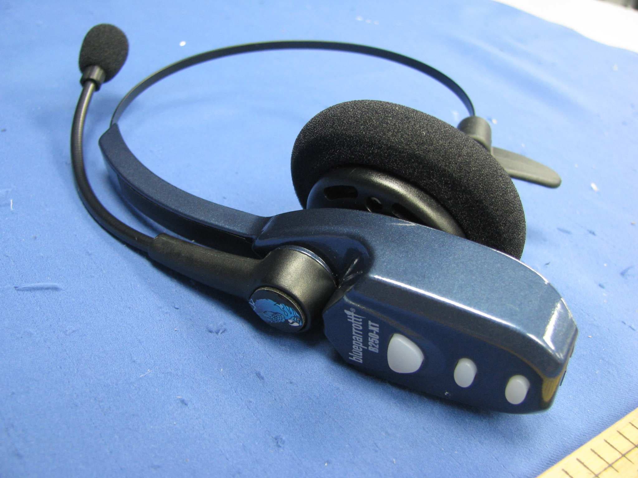
SOM-202720Q
Jul 20, 2011Bluetooth wireless headset
Equipment Class
DXX - Part 15 Low Power Communication Device Transmitter