SOM-203340Bluetooth Dongle
VXI CorporationApplication Details
- Equipment Class
- DSS - Part 15 Spread Spectrum Transmitter
- Date of Grant
- Jun 09, 2013
- Application Purpose
- Original Equipment
- Date of Application
- Jun 09, 2013
- Equipment Note
- Bluetooth Dongle
- Frequency Range
- 2402.00000000 - 2480.00000000
- Company
- VXI Corporation
- Country
- United States
Documents & Files
Document Text
Text extracted from the exhibit documents filed with the FCC. Open a document above to read the original.
Users Manual
© 2013 VXi Corporation VXi CORPORATION 271 Locust Str eet, Dover , NH 03820 603-742-2888 Toll free 800-742-8588 www.vxicorp.c om USER GUIDE BT1 Bluetooth Dongle PN 1X5-DAJ-V0.1 Prin ted in China (1) VXi war rants that your VXi BT1 Bluetooth USB dongle will be free from defects in mater ial and VXi BT1 Bluetooth USB dongle fails to work due to a defect in mater ial or workmanship, VXi will repair or replace the product, at its election, free of charge. Without proof of purchase, the war ranty period begins on the date of manufacture. Consumable components (for example, cushions, batt ery and fuse) are not included in this one-year war ranty. (2) The foregoing limited war ranty does not cover equipment failure attributable to accident, improper operation, misuse, abuse, or any cause other than defects in the mater ials or workmanship of VXi’s products . (3) VXi’s obligations under this war ranty are limited to repair or replacement (at our option) of any defective part returned to VXi at the customer’s expense. Returned products require a Return Authorization that may be obtained by calling 603-742-8588 or visiting www.vxicorp.c om. Products returned to VXi for repair under this war ranty will be return shipped to the customer at VXi’s expense. (4) THIS LIMITED WARRANTY IS IN LIEU OF ALL OTHER WARRANTIES, EXPRESSED OR IMPLIED, INCLUDING THE IMPLIED WARRANTIES OF MERCHANTABILITY AND FITNESS FOR A PARTICULAR PURPOSE. Some jurisdictions do not permit the exclusion of implied war ranties and the foregoing exclusions may not apply to y ou. (5) In no event shall VXi be responsible for any other damages whatsoever , including direct, indirect, special, incidental, consequential, or other damages for breach of this or any other war ranty, expressed or implied. This device complies with part 15 of the FCC rules. Operation is subject to the following two conditions: (1) This device may not cause harmful interfer ence, and (2) This device must accept any interfer ence received, including in terfer ence that may cause undesired operation. Users are not permitted to make changes or modify the device equipment. NOTE: This equipment has been tested and found to comply with the limits for a Class B digital device pursuant to part 15 of the FCC rules. These limits are designed to provide reasonable protection against harmful in terfer ence in a residential installation. This equipment generates, uses and can radiate radio frequency energy and, if not installed and used in accordance with the instructions, may cause harmful interfer ence to radio communications. However , there is no guarantee that interfer ence will not occur in a particular installation. If this equipment does cause harmful interfer ence to radio or television reception, which can be deter mined by turning the equipment – Reorient or relocate the receiving antennae. – Increase the separation between the equipment and the receiver . – Consult the dealer or an experienced radio/TV technician for help. WARRANTY STATEMENT SAFETY INSTRUCTIONS FCC NOTICE TO USERS • Do not immerse any part of this product in water. • Plastic bags and small parts may cause choking if ingested. Keep them away from small children and pets. • Avoid temperatures exceeding 140° F (will cause equipment failure). INSTALLATION 1) Headset Pairing Mode: Put the headset in to pairing mode (voice prompt ‘Discover ing’; should be heard in the headset). 2) Insert The BT1 Into A USB Port On The Computer: Plug the dongle into an available computer USB port. 3) Pairing Mode: The dongle will initialize and go into paring mode while the computer loads the necessary driv er . 4) Headset Will Connect To The Dongle: The headset should connect with the dongle either during the initial- ization process or shortly after . 5) Headset Connected: Once connected you should hear the voice prompt “Your headset is connected”. dongle and repeat this procedure. It may be necessary to so into the PC’s sound settings to prioritize the headset as the primary Microphone and/or Speaker. Please visit www.vxicorp.c om/usb operating syst em. Step #1 Step #2
External Photos
External Photos 1. EUT front view 2. EUT rear view 3. EUT left side view 4. EUT right side view 5. EUT top view 6. EUT bottom view
ID Label/Location Info
Gar net (BT1) Scr een Artwork Version 0.4 Dave Jaques 5/17/2013 Scr een Location Dims = 11mm x 12mm Scr een Location = Bottom of the USB Plug Prin t Style: Etching Made In China Model: BT1 FCC ID: SOM-203340 Made In China Model: BT1 FCC ID: SOM-203340 Actual Art (100%) LOCATIONARTWORK Outline Art (100%) Read Version (200%) - NOT FOR PRINT Made In China Model: BT1 FCC ID: SOM-203340 Made In China Model: BT1 FCC ID: SOM-203340 LOCATIONARTWORK
Internal Photos
Internal Photos 1. Mainboard front view and BT Antenna 2. Mainboard rear view
Test Report
SZ13020008W02 Page 2 of 87 DIRECTORY 1. GENERAL INFORMATION .................................................................................................... 3 1.1. EUT Description ....................................................................................................................... 3 1.2. Test Standards and Results ........................................................................................................ 4 1.3. Facilities and Accreditations ..................................................................................................... 5 2. 47 CFR PART 15C REQUIREMENTS .................................................................................... 6 2.1. Antenna requirement ................................................................................................................. 6 2.2. Number of Hopping Frequency ................................................................................................ 6 2.3. Peak Output Power.................................................................................................................. 12 2.4. 20dB Bandwidth ..................................................................................................................... 14 2.5. Carried Frequency Separation ................................................................................................. 21 2.6. Time of Occupancy (Dwell time) ........................................................................................... 24 2.7. Conducted Spurious Emissions ............................................................................................... 36 2.8. Band Edge ............................................................................................................................... 49 2.9. Conducted Emission ............................................................................................................... 66 2.10. Radiated Emission................................................................................................................... 69 Change History Issue Date Reason for change 1.0 May 21, 2013 First edition 2.0 June 4, 2013 Second edition 3.0 June 5, 2013 Third edition SZ13020008W02 Page 3 of 87 1. General Information 1.1. EUT Description EUT Type ............................. : Bluetooth Dongle Serial No. .............................. : (n.a, marked #1 by test site) Hardware Version ................. : V1.0 Software Version .................. : Applicant .............................. : Manufacturer ........................ : V1.0 VXI Corporation 271 Locust Street , Dover, NH 03820, USA OCVACO ELECTRONIC LIMITED No.142, South Tanshen Road, Tanzhou Town, Zhongshan City, Guangdong province, 528467, China. Frequency Range .................. : The frequency range used is 2402MHz - 2480MHz (79 channels, at intervals of 1MHz); The frequency block is 2400MHz to 2483.5MHz. Modulation Type .................. : Bluetooth: FHSS (GFSK(1Mbps), ∏/4-DQPSK(EDR 2Mbps), 8-DPSK(EDR 3Mbps)) Antenna Type ........................ : PCB Antenna Gain ........................ : 0dBi Note 1: The EUT is a Bluetooth Dongle, it contains Bluetooth Module operating at 2.4GHz ISM band; the frequencies allocated for the Bluetooth Module is F(MHz)=2402+1*n (0<=n<=78). The lowest, middle, highest channel numbers of the Bluetooth Module used and tested in this report are separately 0 (2402MHz), 39 (2441MHz) and 78 (2480MHz). Note 2: For a more detailed description, please refer to Specification or User’s Manual supplied by the applicant and/or manufacturer. Note 3: a. When power on, the EUT will scan the whole frequency until a Connection command from the other BT devices. b. When receiving the signal from the other BT devices, The EUT transmit aresponse signal. c. The other devices receive the response signal and recognize it, then send a connection command to establish the connection. d. After the connection establish successfully, the data transmission is beginning. At the same time, the both devices will shift frequencies in synchronization per a same pseudo randomly ordered list of hopping frequencies, the hopping rate is1600 times per second. This device conforms to the criteria in FCC Public Notice DA 00-705. e. The bandwidth of the receiver, which is set to a fixed width by the software. Note 4: Bluetooth signal has 9 packages DH1, DH3, DH5, 3DH1, 3DH3, 3DH5, 5DH1, 5DH3, 5DH5, DH5 package is largest, we are testing DH5 in the document. SZ13020008W02 Page 4 of 87 1.2. Test Standards and Results The objective of the report is to perform testing according to 47 CFR Part 15 Subpart C (Bluetooth, 2.4GHz ISM band radiators) for the EUT FCC ID Certification: No. Identity Document Title 1 47 CFR Part 15 (10-1-09 Edition) Radio Frequency Devices Test detailed items/section required by FCC rules and results are as below: No. Section in CFR 47Description Result 1 15.203 Antenna Requirement PASS 2 15.247(a) Number of Hopping Frequency PASS 3 15.247(b) Peak Output Power PASS 4 15.247(a) 20dB Bandwidth PASS 5 15.247(a) Carrier Frequency Separation PASS 6 15.247(a) Time of Occupancy (Dwell time) PASS 7 15.247(d) Conducted Spurious Emission PASS 8 15.247(d) Band Edge PASS 9 15.207 Conducted Emission PASS 10 15.209 15.247(d) Radiated Emission PASS NOTE: The tests were performed according to the method of measurements prescribed in DA-00-705. SZ13020008W02 Page 5 of 87 1.3. Facilities and Accreditations 1.3.1. Facilities Shenzhen Morlab Communications Technology Co., Ltd. Morlab Laboratory is a testing organization accredited by China National Accreditation Service for Conformity Assessment (CNAS) according to ISO/IEC 17025. The accreditation certificate number is L3572. All measurement facilities used to collect the measurement data are located at FL.1, Building A, FeiYang Science Park, Block 67, BaoAn District, Shenzhen, 518101 P. R. China. The test site is constructed in conformance with the requirements of ANSI C6…
Text truncated - open the document above for the full version.
Test Setup Photos
Test Setup Photos 1. Conducted emission main’s port front view 2. Conducted emission main’s port side view 3. Radiated emission (9KHz-30MHz) 4. Radiated emission (30MHz-1GHz) 5. CSE
Contact Information
Applicant
David Geno(Electrical Engineer)
Technical Contact
Shenzhen Morlab Communications Technology Co.,LtdIvy Zhu
[email protected]+86-755-36698618
FL.3,Electronic Testing Building · Shenzhen, Guangdong · China
Test Firm
Shenzhen Morlab Communications Technology Co.,LtdShu Luan
Technical Specifications
| # | Rule Parts | Frequency Range | Power Output |
|---|---|---|---|
| 1 | 15C | 2.40 GHz - 2.48 GHz | 1.00 mW |
Other Applications from VXI Corporation
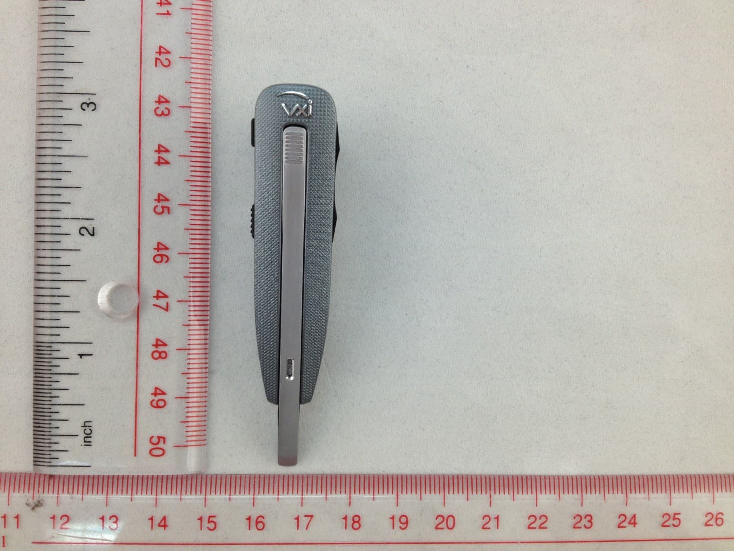
SOM-203535
Aug 11, 2014Bluetooth Headset
Equipment Class
DSS - Part 15 Spread Spectrum Transmitter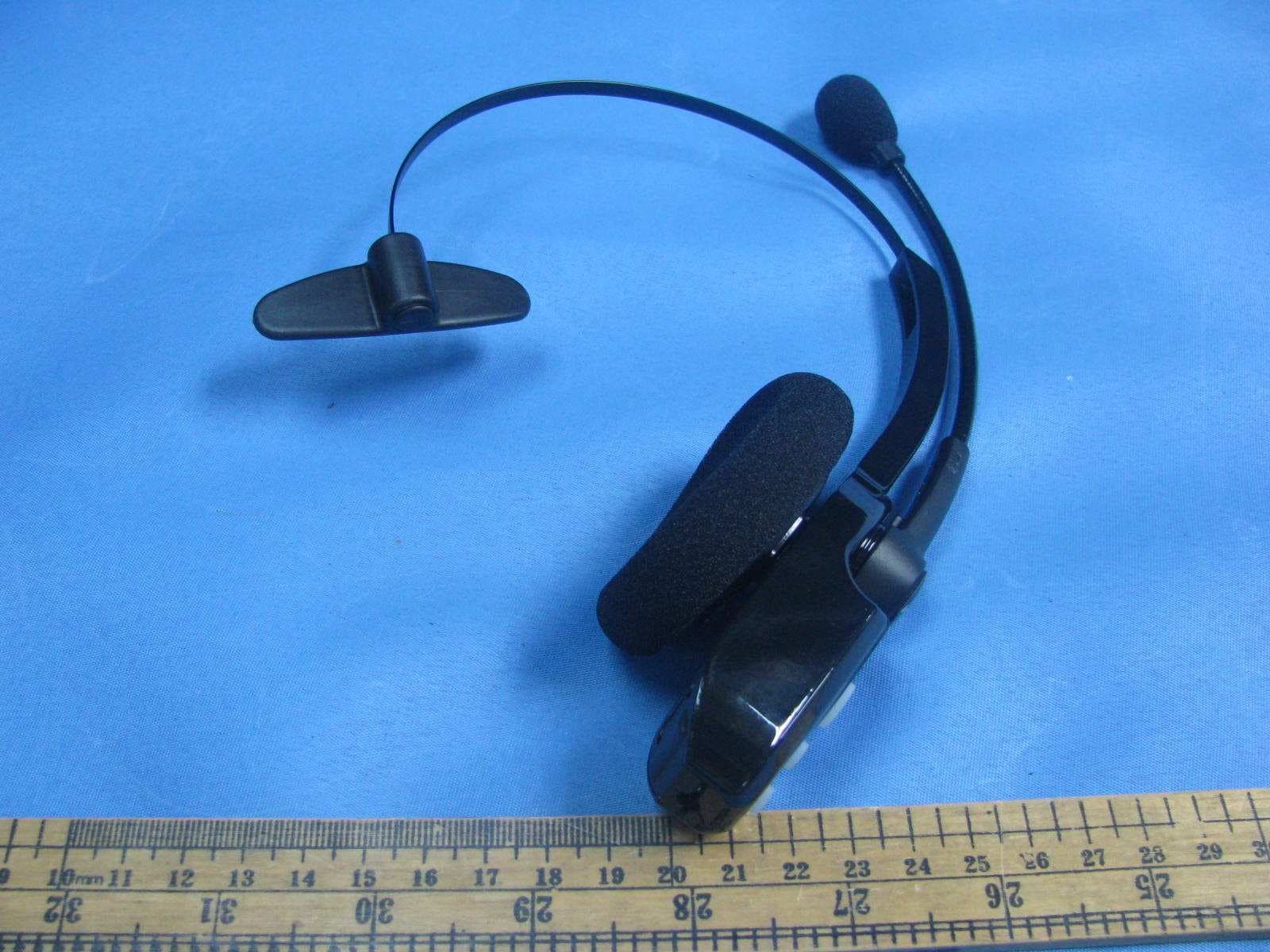
SOM-203100
Nov 20, 2011Bluetooth wireless headset
Equipment Class
DXX - Part 15 Low Power Communication Device Transmitter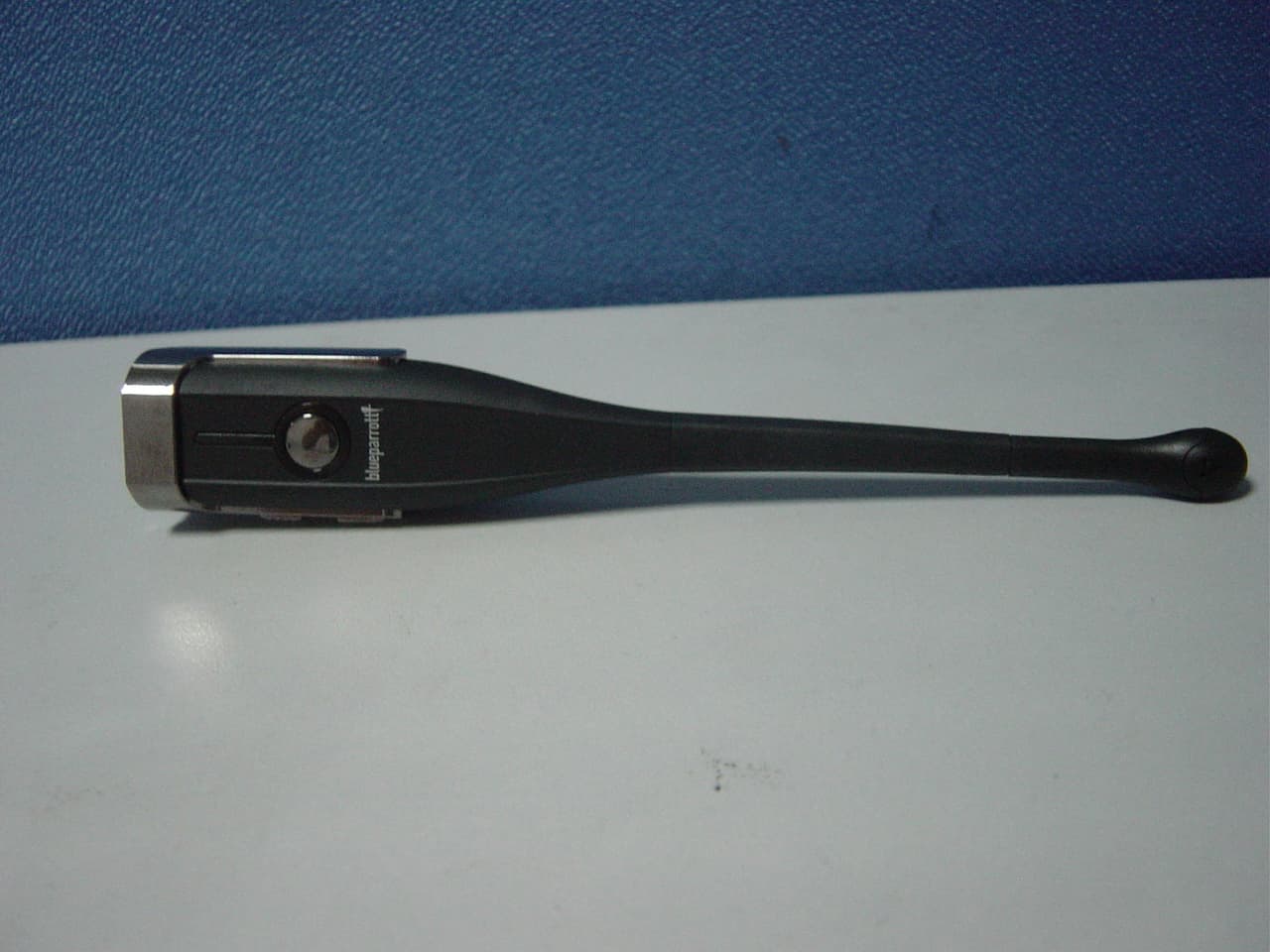
SOM-203099
Aug 31, 2011BLUETOOTH EARPHONE
Equipment Class
DSS - Part 15 Spread Spectrum Transmitter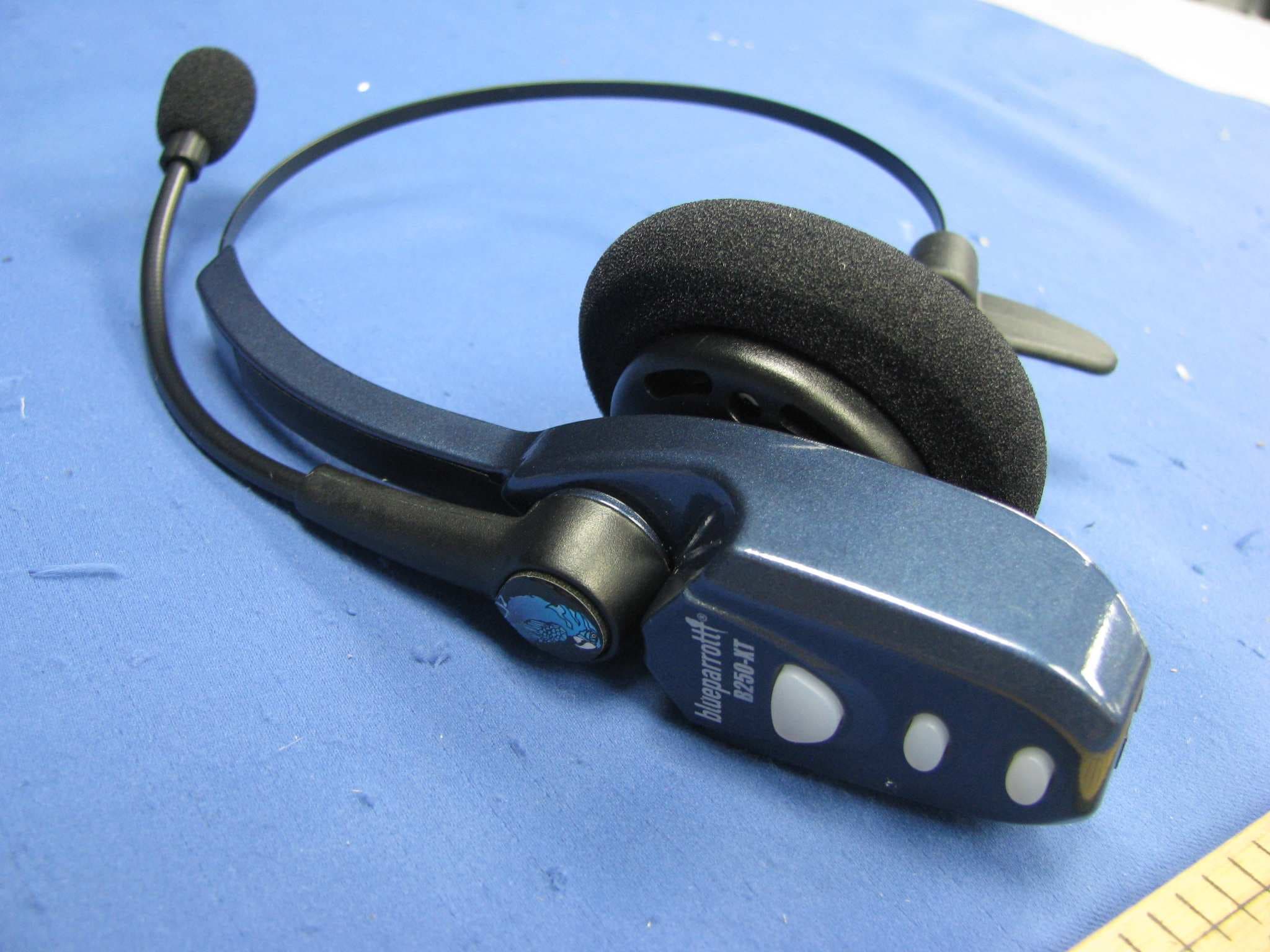
SOM-202720Q
Jul 20, 2011Bluetooth wireless headset
Equipment Class
DXX - Part 15 Low Power Communication Device Transmitter
SOM-201548
Nov 21, 2004BT Base Station for BT Headset
Equipment Class
DSS - Part 15 Spread Spectrum Transmitter