SOM-202720QBluetooth wireless headset
VXI Corporation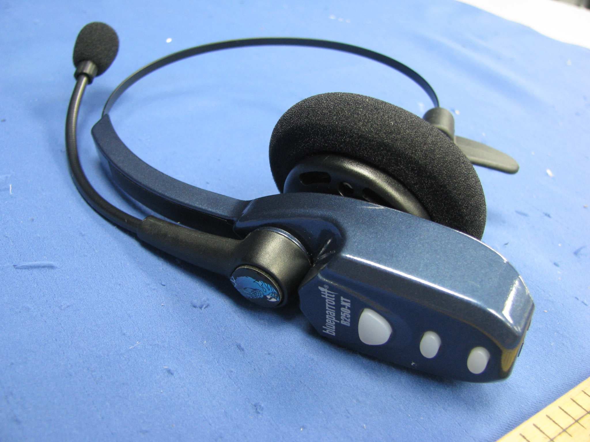
Click to zoom
Application Details
- Equipment Class
- DXX - Part 15 Low Power Communication Device Transmitter
- Date of Grant
- Jul 20, 2011
- Application Purpose
- Original Equipment
- Date of Application
- Jul 20, 2011
- Equipment Note
- Bluetooth wireless headset
- Frequency Range
- 2402.00000000 - 2480.00000000
- Company
- VXI Corporation
- Country
- United States
Documents & Files
Document Text
Text extracted from the exhibit documents filed with the FCC. Open a document above to read the original.
Users Manual
Turn Headset On: Hold down the MFB for 2-3 seconds until you hear 2 rising tones. The red light will fl ash once every second. Standby Mode: After the headset is turned on, it will attempt to connect to the last device that it was paired with, putting itself into standby mode. The headset can also be put into standby mode with a quick press and release of the MFB. The blue light will fl ash indicating an active Bluetooth link. Turn Headset Off (conserves battery power): Hold down the MFB for 2-3 seconds until you hear 2 falling tones. A red light will fl ash 4 times and the headset will turn off. Position microphone near corner of your mouth. Correct positioning ensures that the noise cancellation technology works properly. Slight adjustment of the microphone may help to achieve optimum performance. HEADSET CONTROLS 4 Volume Increase: Quickly press and release the Volume Up/Mute button. Repeat until desired volume is attained. Volume Decrease: Quickly press and release the Volume Down button. Repeat until desired volume is attained. Microphone Mute/Un-Mute: Hold down the Volume Up/ Mute button for 2 seconds until you hear a beep. A mute reminder beep will be heard every 10 seconds. Repeat to un-mute. Multifunction Button (MFB) & Indicator Lights Volu me Up & Microphone Mute Volu me D ow n After the initial 12 hour charge, the indicator lights will indicate the level of battery power as follows. Green light: Fully charged. Up to 16 hours talk time. Green & red lights together: Approximately 60 seconds away from full charge. Red light: Less than a full charge. TIPS BATTERY POWER INDICATORS 3 Select charger cord and plug it into the charger port on the headset. Charge for 12 full hours before fi rst use. Note: If you do not use your headset for a long period of time, you should repeat this 12 hour charge. AC Charger DC Charger TABLE OF CONTENTS 1 - Safety Instructions / Glossary 2 - Charge the Headset 3 - Battery Power Indicators 4 - Headset Controls 5 - On / Standby / Off 6 - Pair Headset with the Phone 7 - Microphone Positioning 8 - Make a Call / End a Call 9 - Answer a Call / End a Call 10 - Pairing with a Computer 11 - Operation While Using the Charger/Adapter 12 - Last Number Redial 12- Reject a Call 13 - Voice Dial 13 - Transfer Audio 14- Turn Headset Indicator Lights Off/On 14- Automatic Bluetooth Connection 15- Multiple Device Pairing 16- Reset Paired Devices List 17- Specifi cations Keep charger plugged into headset when not in use to avoid battery drain. It’s not necessary for the charger to be plugged into a power source to take advantage of this. Avoid hearing damage. Set volume at lowest comfortable level. If you experience ringing in your ears or people sound muffl ed, stop using the headset. Avoid turning up volume to block noisy surroundings (it’s possible to adapt to volume that is too high). Check with local and state laws regarding cell phone handset usage while operating a motor vehicle. Replace only with same or equivalent battery. Dispose of batteries according to local regulations. Do not throw batteries in a fi re, as they could explode. Do not immerse any part of this product in water. Plastic bags and small parts may cause choking if ingested. Keep them away from small children and pets. Use only the power cords included with this product. Avoid temperatures exceeding 140°F (will cause equipment failure). GLOSSARY OF TERMS Paired- Two Bluetooth devices agree to communicate with one another. On - Headset is on but there is no connection to the phone (red light will fl ash). Standby Mode - Headset is on, Bluetooth link is active, the user is not on a call (blue light will fl ash). Talk Mode- Headset is being used with the cell phone while the cell phone is on an active call. PAIR HEADSET WITH THE PHONE 6 PAIRING WITH A COMPUTER 10 MAKE A CALL / END A CALL 8 OPERATION WHILE USING THE CHARGER / ADAPTER 11 SAFETY INSTRUCTIONS/GLOSSARY 1 5 ON / STANDBY / OFF 1. Turn headset off (panel 5). 2. Hold down the headset’s MFB until the red and blue lights fl ash and you hear 2 rising tones, followed by 4 more tones. Important: Wait for all tones and for both lights to fl ash. This may take up to 15 sec. Release the MFB. 3. Follow the manufacturer’s instructions for putting your cellular phone into Bluetooth discovery mode. 4. Wait 5-15 sec. while the devices discover each other. When the phone discovers the headset, select “Pair” and enter a passcode of 0000 when instructed. When pairing is complete the headset’s blue light will stop fl ashing and the phone will prompt you to ‘connect’ to the headset. Enter “Yes” on the phone to connect to the headset. When connected, the blue light will fl ash indicating that the headset is in standby mode ready to receive a call. Keep headset & phone no less than 3 inches and no more than 3 feet apart while pairing. Keep other Bluetooth devices at least 50 ft. away or turn them off. Note: The headset can be paired with up to 3 different devices. If you have not paired the headset and phone together yet, you must do so (panel 6). 1. Turn on your cell phone. Be sure the Bluetooth option is enabled on your phone (refer to your phone’s user guide for instruction). 2. Put headset on and properly position the microphone (panel 7). To turn headset on press MFB for 2-3 seconds. The headset will automatically attempt to connect with the last device it was paired or connected with. Once connected, the headset will enter standby mode. 3. Dial the phone and make a call as usual. 4. To end call, quickly press the MFB on the headset and release. You will hear 2 falling tones; the call will end and the headset will enter standby mode. In order to answer a call, the headset must be in standby mode (panel 5). 1. Put headset on. Position the microphone (panel 7). 2. When your cell phone rings, you will hear ring tones in the headset. Answer the call by quickly pressing the headset’s MFB and release. 3. To end the call, quickly press the MFB on the headset and …
Text truncated - open the document above for the full version.
Cover Letter(s)
FCC ID: SOM-202720Q
External Photos
External Photos
ID Label/Location Info
Label Location and Artwork
Internal Photos
Internal Photos
Test Report
Ref 97 dBμVAtt 0 dB * A Center 2.4 GHzSpan 10 MHz1 MHz/ * * 3DB RBW 100 kHz VBW 300 kHz SWT 2.5 ms 1 PK MAXH 0 10 20 30 40 50 60 70 80 90 1 Marker 1 [T1 ] 72.29 dBμV 2.402000000 GHz 1 Delta 1 [T1 ] -40.01 dB -2.020000000 MHz Ref 97 dBμVAtt 0 dB * A Center 2.4835 GHzSpan 10 MHz1 MHz/ * * 3DB RBW 100 kHz VBW 300 kHz SWT 2.5 ms 1 PK MAXH 0 10 20 30 40 50 60 70 80 90 1 Marker 1 [T1 ] 71.52 dBμV 2.479960000 GHz 1 Delta 1 [T1 ] -42.18 dB 4.040000000 MHz
Test Report
Ref 97 dBμVAtt 0 dB ** A Center 2.402 GHzSpan 3 MHz300 kHz/ * * RBW 100 kHz VBW 300 kHz SWT 100 ms 3DB * 1 PK MAXH 0 10 20 30 40 50 60 70 80 90 1 Marker 1 [T1 ] 71.69 dBμV 2.401982000 GHz ndB [T1] 20.00 dB BW 1.134000000 MHz T1 Temp 1 [T1 ndB] 52.16 dBμV 2.401424000 GHz T2 Temp 2 [T1 ndB] 51.58 dBμV 2.402558000 GHz Ref 97 dBμVAtt 0 dB ** A Center 2.48 GHzSpan 3 MHz300 kHz/ 1 PK MAXH 3DB SWT 100 ms * * * RBW 100 kHz VBW 300 kHz 0 10 20 30 40 50 60 70 80 90 1 Marker 1 [T1 ] 71.62 dBμV 2.480000000 GHz ndB [T1] 20.00 dB BW 1.140000000 MHz T1 Temp 1 [T1 ndB] 51.28 dBμV 2.479418000 GHz T2 Temp 2 [T1 ndB] 51.49 dBμV 2.480558000 GHz
Test Report
Intertek Testing Services Shenzhen Ltd. Kejiyuan Branch 6F, D Block, Huahan Building, Langshan Road, Nanshan District, Shenzhen, P. R. China Tel: (86 755) 8601 6288 Fax: (86 755) 8601 6751 Website: www.china.intertek-etlsemko.com Dec 8, 2010 VXI Corporation 271 Locust Street, Dover New Hampshire 03820 United States Dear David Geno: Enclosed you will find your file copy of a Part 15 Certification (FCC ID: SOM-202720Q). For your reference, TCB will normally take another 5 days for reviewing the report. Approval will then be granted when no query is sorted. Please contact me if you have any questions regarding the enclosed material. Sincerely, Shawn Xing Assistant Manager Enclosure • The test results reported in this test report shall refer only to the sample actually tested and shall not refer or be deemed to refer to bulk from which such a sample may be said to have been obtained. • This report is for the exclusive use of Intertek's Client and is provided pursuant to the agreement between Intertek and its Client. Intertek's responsibility and liability are limited to the terms and conditions of the agreement. Intertek assumes no liability to any party, other than to the Client in accordance with the agreement, for any loss, expense or damage occasioned by the use of this report. Only the Client is authorized to copy or distribute this report. Any use of the Intertek name or one of its marks for the sale or advertisement of the tested material, product or service must first be approved in writing by Intertek. The observations and test results referenced from this report are relevant only to the sample tested. This report by itself does not imply that the material, product, or service is or has ever been under an Intertek certification program. • For Terms And Conditions of the services, it can be provided upon request. • The evaluation data of the report will be kept for 3 years from the date of issuance. TRF No.: FCC 15C_TXa FCC ID: SOM-202720Q Intertek Testing Services Shenzhen Ltd. Kejiyuan Branch 6F, D Block, Huahan Building, Langshan Road, Nanshan District, Shenzhen, P. R. China Tel: (86 755) 8601 6288 Fax: (86 755) 8601 6751 Website: www.china.intertek-etlsemko.com VXI Corporation Application For Certification (FCC ID: SOM-202720Q) Bluetooth wireless headset Model: B250-XT 2.4GHz Transceiver We hereby certify that the sample of the above item is considered to comply with the requirements of FCC Part 15, Subpart C for Intentional Radiator, mention 47 CFR [ 10-1-09] SZ10060105-1 Billy Li Dec 8, 2010 INTERTEK TESTING SERVICES TRF No.: FCC 15C_TXa FCC ID: SOM-202720Q i LIST OF EXHIBITS INTRODUCTION EXHIBIT 1: General Description EXHIBIT 2: System Test Configuration EXHIBIT 3: Emission Results EXHIBIT 4: Equipment Photographs EXHIBIT 5: Product Labelling EXHIBIT 6: Technical Specifications EXHIBIT 7: Instruction Manual EXHIBIT 8: Miscellaneous Information EXHIBIT 9: Test Equipment List INTERTEK TESTING SERVICES TRF No.: FCC 15C_TXa FCC ID: SOM-202720Q ii MEASUREMENT/TECHNICAL REPORT VXI Corporation - MODEL: B250-XT FCC ID: SOM-202720Q Dec 8, 2010 This report concerns (check one:) Original Grant X Class II Change Equipment Type: DXX - Part 15 Low Power Communication Device Transmitter Deferred grant requested per 47 CFR 0.457(d)(1)(ii)? Yes No X If yes, defer until: date Company Name agrees to notify the Commission by: date of the intended date of announcement of the product so that the grant can be issued on that date. Transition Rules Request per 15.37? Yes No X If no, assumed Part 15, Subpart C for intentional radiator − the new 47 CFR [10-1-09 Edition] provision. Report prepared by: Shawn Xing Intertek Testing Services Shenzhen Ltd. Kejiyuan Branch 6F, Block D, Huahan Building, Langshan Road, Nanshan District, Shenzhen, P. R. China Phone: (86 755) 8601 6288 Fax: (86 755) 8601 6751 INTERTEK TESTING SERVICES TRF No.: FCC 15C_TXa FCC ID: SOM-202720Q iii Table of Contents 1.0 General Description............................................................................................ 2 1.1 Product Description ............................................................................................ 2 1.2 Related Submittal(s) Grants ............................................................................... 2 1.3 Test Methodology............................................................................................... 3 1.4 Test Facility........................................................................................................ 3 2.0 System Test Configuration ................................................................................. 5 2.1 Justification ........................................................................................................ 5 2.2 EUT Exercising Software.................................................................................... 5 2.3 Special Accessories ........................................................................................... 5 2.4 Equipment Modification ...................................................................................... 5 2.5 Measurement Uncertainty .................................................................................. 6 2.6 Support Equipment List and Description ............................................................. 6 3.0 Emission Results ................................................................................................ 8 3.1Radiated Test Results............................................................................ 9 3.1.1 Field Strength Calculation................................................................................ 9 3.1.2 Radiated Emission Configuration Photograph ................................................ 10 3.1.3 Radiated Emissions....................................................................................... 10 3.1.4 Transmitter Spurious Emissions (Radiated)............................................ 12 3.2 Cond…
Text truncated - open the document above for the full version.
Test Setup Photos
Conducted Emission
Test Setup Photos
Radiated Emission
Contact Information
Applicant
David Geno(Electrical Engineer)
Technical Contact
Intertek Testing Services Shenzhen Ltd KejiyuanShawn Xing
[email protected]8675586140603
6F, D Block, Huahan Building, Langshan Road · Shenzhen · China
Non-Technical Contact
Intertek Testing Services Shenzhen Ltd KejiyuanShawn Xing
[email protected]8675586140603
Test Firm
Intertek Testing Services Shenzhen Ltd.Shawn Xing
Technical Specifications
| # | Rule Parts | Frequency Range | Power Output |
|---|---|---|---|
| 1 | 15C | 2.40 GHz - 2.48 GHz | - |
Other Applications from VXI Corporation
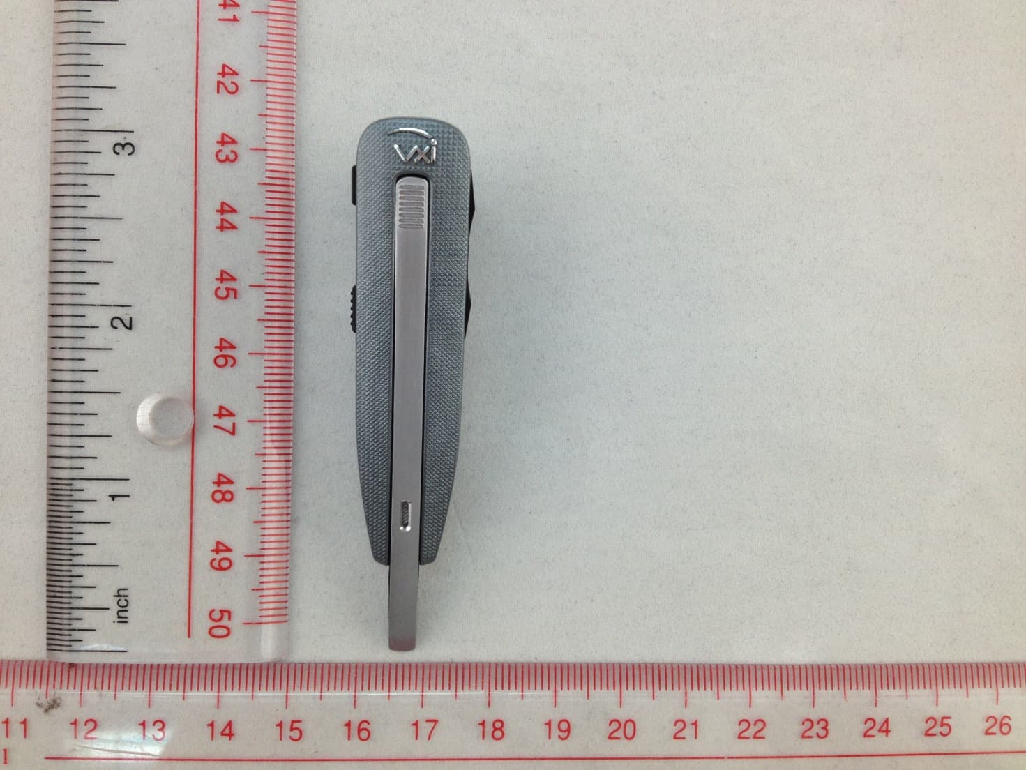
SOM-203535
Aug 11, 2014Bluetooth Headset
Equipment Class
DSS - Part 15 Spread Spectrum TransmitterSOM-203340
Jun 09, 2013Bluetooth Dongle
Equipment Class
DSS - Part 15 Spread Spectrum Transmitter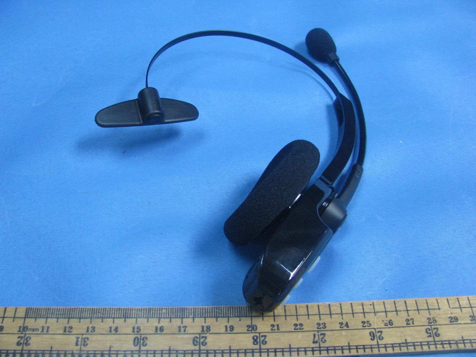
SOM-203100
Nov 20, 2011Bluetooth wireless headset
Equipment Class
DXX - Part 15 Low Power Communication Device Transmitter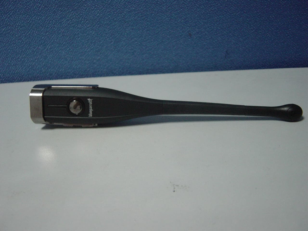
SOM-203099
Aug 31, 2011BLUETOOTH EARPHONE
Equipment Class
DSS - Part 15 Spread Spectrum Transmitter
SOM-201548
Nov 21, 2004BT Base Station for BT Headset
Equipment Class
DSS - Part 15 Spread Spectrum Transmitter