SOY-HBB1BROADBAND BOOSTER
Hawking Technologies, Inc.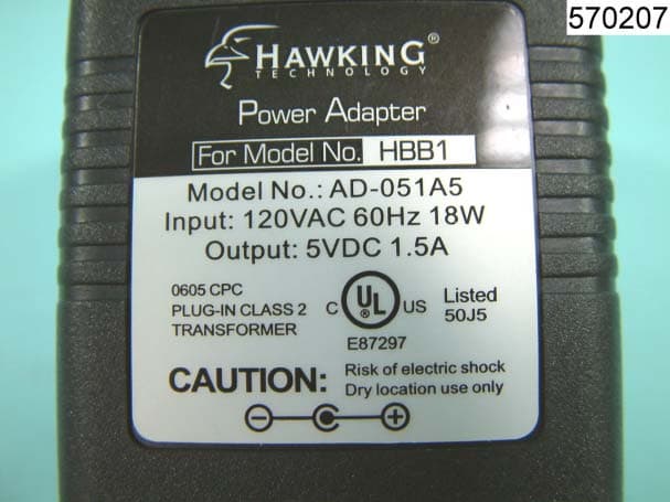
Click to zoom
Application Details
- Equipment Class
- JBP - Part 15 Class B Computing Device Peripheral
- Date of Grant
- Sep 14, 2005
- Application Purpose
- Original Equipment
- Date of Application
- Sep 14, 2005
- Equipment Note
- BROADBAND BOOSTER
- Company
- Hawking Technologies, Inc.
- Country
- United States
Documents & Files
Document Text
Text extracted from the exhibit documents filed with the FCC. Open a document above to read the original.
Users Manual
Table of Contents 2 Warranty Information 3 Certifications 4 What You Need to Get Started Package Contents Product Description Quick Start Installation 11 How the Broadband Booster Works Broadband Booster Overview Which Applications will Benefit Most from the Broadband Booster Introducing StreamEngine Technology 16 Accessing the Advanced Configuration Menu Information/Status Menu Advanced Configuration Menu Administration Menu Setting the Username and Password 23 Tips and Frequently Asked Questions 26 Service and Support 1 LIMITED WARRANTY Hawking Technology guarantees that every HBB1 Broadband Booster is free from physical defects in material and workmanship under normal use for two (2) years from the date of purchase. If the product proves defective during this two-year warranty period, call Hawking Customer Service in order to obtain a Return Authorization number. The warranty is for repair or replacement only. Hawking Technology does not issue any refunds. BE SURE TO HAVE YOUR PROOF OF PURCHASE. RETURN REQUESTS CANNOT BE PROCESSED WITHOUT PROOF OF PURCHASE. When returning a product, mark the Return Authorization number clearly on the outside of the package and include your original proof of purchase. IN NO EVENT SHALL HAWKING TECHNOLOGY’S LIABILITY EXCEED THE PRICE PAID FOR THE PRODUCT FROM DIRECT, INDIRECT, SPECIAL, INCIDENTAL OR CONSEQUENTIAL DAMAGES RESULTING FROM THE USE OF THE PRODUCT, ITS ACCOMPANYING SOFTWARE OR ITS DOCUMENTATION. Hawking Technology makes no warranty or representation, expressed, implied or statutory, with respect to its products or the contents or use of this documentation and all accompanying software, and specifically disclaims its quality, performance, merchantability, or fitness for any particular purpose. Hawking Technology reserves the right to revise or update its products, software, or documentation without obligation to notify any individual or entity. Please direct all inquiries to: [email protected]. 2 3 FCC WARNING This equipment has been tested and found to comply with the limits for a Class B digital device, pursuant to Part 15 of the FCC Rules. These limits are designed to provide reasonable protection against harmful interference in a residential installation. This equipment generates, uses and can radiated radio frequency energy and, if not installed and used in accordance with the instructions, may cause harmful interference to radio communications. However, there is no guarantee that interference will not occur in a particular installation If this equipment does cause harmful interference to radio or television reception, which can be determined by turning the equipment off and on, the user is encouraged to try to correct the interference by one or more of the following measures: -Reorient or relocate the receiving antenna. -Increase the separation between the equipment and receiver. -Connect the equipment into an outlet on a circuit different from that to which the receiver is connected. -Consult the dealer or an experienced radio/TV technician for help. Changes or modifications not expressly approved by the party responsible for compliance could void the user‘s authority to operate the equipment. CE MARK WARNING This is a Class B product. In a domestic environment, this product may cause radio interference, in which case the user may be required to take adequate measures. 4 5 Quick Start Setting Up the Broadband Booster in Your Network 6 The Broadband Booster is placed in-between your Cable or DSL Modem and your network Router. 7 8 9 10 How The Broadband Booster Works Introducing Stream Engine Technology The Broadband Booster sits between the broadband modem and router. It optimizes networks for interactive applications used by A) multiple users, and B) individual users. Overview The Hawking Broadband Booster is a new class of product: a network upgrade that solves problems with using time-sensitive applications on broadband internet connections. It improves the playability of online games, maintains VoIP call quality, and 11 12 enhances the quality of streaming video without any configuration required by the user. Target Applications High speed internet connections are making interactive applications such as online games, VoIP, file and application sharing, and video conferencing more popular. These new technologies work very well, but people run into problems when they try to use more than one application at the same time. Here are some examples of when this can happen: - A hard-core gamer notices his online first-person shooting game starts to “lag” or behave erratically when others in the house surf the web or do e-mail. - A manager of a small office subscribes to a VoIP service to reduce long-distance phone bills. She is frustrated when her calls break up when someone else in the office sends an e-mail attachment. - A father uses a web cam to monitor his children at home with the babysitter. He has to remember to turn off the file sharing application on his home computer before leaving in the morning. When it is on, the video from the web cam gets disrupted. - A manager with a single home computer wants to run a late- night training session for her worldwide sales force from home. The internet connection has plenty of bandwidth, but it can’t seem to handle both sharing the presentation and the VoIP call both reliably and at the same time. Simply put, the Broadband Booster is an easily-installed device that provides broadband users with a superior experience of the internet. Simple Installation and Automatic Operation The Broadband Booster plugs in directly between the broadband modem and a computer, router, gateway, or access point, with a single Ethernet port for each device. It requires no configuration by the user, and has clear status lights to show it is working correctly. In most cases, the settings of the modem and router do not need to be changed to work with the Broadband Booster. This is great for home or small off…
Text truncated - open the document above for the full version.
Block Diagram
HBB1 Block Diagram
External Photos
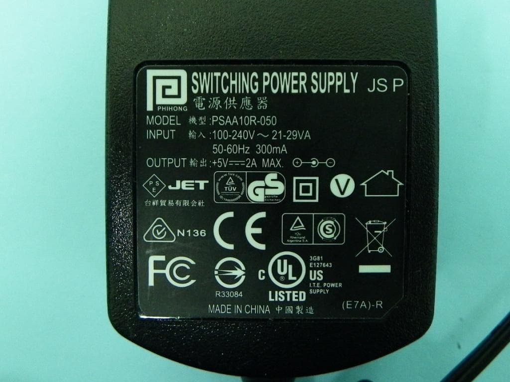
FCC ID: SOY-HBB1 Number 1 FRONT SIDE OF EUT FCC ID: SOY-HBB1 Number 2 REAR SIDE OF EUT FCC ID: SOY-HBB1 Number 3 ADAPTER FCC ID: SOY-HBB1 Number 4 ADAPTER FCC ID: SOY-HBB1 Number 5 FRONT SIDE OF ADAPTER FCC ID: SOY-HBB1 Number 6 ADAPTER FCC ID: SOY-HBB1 Number 7 ADAPTER FCC ID: SOY-HBB1 Number 8 FRONT SIDE OF ADAPTER FCC ID: SOY-HBB1 Number 9 REAR SIDE OF ADAPTER
ID Label/Location Info
FCC ID: SOY-HBB1 Label Location
Internal Photos
FCC ID : SOY-HBB1 Number 1 CLOSER LOOK OF INTERFACE PORT FCC ID : SOY-HBB1 Number 2 CLOSER LOOK OF INTERFACE PORT FCC ID : SOY-HBB1 Number 3 CLOSER LOOK OF INTERFACE PORT FCC ID : SOY-HBB1 Number 4 MECHANICAL CONSTRUCTION OF EUT FCC ID : SOY-HBB1 Number 5 FRONT SIDE OF MAIN BOARD FCC ID : SOY-HBB1 Number 6 REAR SIDE OF MAIN BOARD
Test Report
FCC TEST REPORT Report No. : FC570207 SPORTON International Inc. TEL : 886-2-2696-2468 FAX : 886-2-2696-2255 FCC TEST REPORT for 47 CFR, Part 15, Subpart B Equipment : Broadband Booster Model No. : HBB1 FCC ID : SOY-HBB1 Filing Type : Certification Applicant : Hawking Technologies, Inc 15281A Barranca parkway, Irvine, CA 92618 USA The test result refers exclusively to the test presented test model / sample. Without written approval of SPORTON International Inc., the test report shall not be reproduced except in full. Certificate or Test Report must not be used by the applicant to claim the product in this test report endorsement by NVLAP or any agency of U.S. government. SPORTON International Inc. 6F, No.106, Sec. 1, Hsin Tai Wu Rd., Hsi Chih, Taipei Hsien, Taiwan, R.O.C. FCC TEST REPORT Report No. : FC570207 SPORTON International Inc. FCC ID : SOY-HBB1 TEL : 886-2-2696-2468 Page No. : i FAX : 886-2-2696-2255 Issued Date : Aug. 03, 2005 Table of Contents History of this test report..................................................................................................................ii CERTIFICATE OF COMPLIANCE........................................................................................................................1 1. General Description of Equipment under Test.............................................................................................2 1.1. Applicant..........................................................................................................................................................................................2 1.2. Manufacturer ...................................................................................................................................................................................2 1.3. Basic Description of Equipment under Test ....................................................................................................................................2 1.4. Feature of Equipment under Test ...................................................................................................................................................2 2. Test Configuration of Equipment under Test ...............................................................................................3 2.1. Test Manner ....................................................................................................................................................................................3 2.2. Description of Test System .............................................................................................................................................................3 2.3. Connection Diagram of Test System ..............................................................................................................................................5 3. Test Software ...................................................................................................................................................6 4. General Information of Test............................................................................................................................7 4.1. Test Facility .....................................................................................................................................................................................7 4.2. Test Voltage ....................................................................................................................................................................................7 4.3. Standard for Methods of Measurement...........................................................................................................................................7 4.4. Test in Compliance with ..................................................................................................................................................................7 4.5. Frequency Range Investigated .......................................................................................................................................................7 4.6. Test Distance ..................................................................................................................................................................................7 5. Test of Conducted Powerline .........................................................................................................................8 5.1. Major Measuring Instruments..........................................................................................................................................................8 5.2. Test Procedures ..............................................................................................................................................................................9 5.3. Typical Test Setup Layout of Conducted Powerline .....................................................................................................................10 5.4. Test Result of AC Powerline Conducted Emission .......................................................................................................................11 6. Test of Radiated Emission............................................................................................................................15 6.1. Major Measuring Instruments........................................................................................................................................................15 6.2. Test Procedures ............................................................................................................................................................................16 6.3. Typical Test Setup Layout of Radiated Emission..........................................................................................................................17 6.4. Test Result of Radi…
Text truncated - open the document above for the full version.
Test Setup Photos
FCC TEST REPORT Report No. : FC570207 SPORTON International Inc. FCC ID : SOY-HBB1 TEL : 886-2-2696-2468 Page No. : 1 of 6 FAX : 886-2-2696-2255 Issued Date : Aug. 03, 2005 1.1. Photographs of Conducted Powerline Test Configuration z The photographs show the configuration that generates the maximum emission. Mode 1 FRONT VIEW REAR VIEW FCC TEST REPORT Report No. : FC570207 SPORTON International Inc. FCC ID : SOY-HBB1 TEL : 886-2-2696-2468 Page No. : 2 of 6 FAX : 886-2-2696-2255 Issued Date : Aug. 03, 2005 FRONT VIEW FCC TEST REPORT Report No. : FC570207 SPORTON International Inc. FCC ID : SOY-HBB1 TEL : 886-2-2696-2468 Page No. : 3 of 6 FAX : 886-2-2696-2255 Issued Date : Aug. 03, 2005 Mode 2 FRONT VIEW REAR VIEW FCC TEST REPORT Report No. : FC570207 SPORTON International Inc. FCC ID : SOY-HBB1 TEL : 886-2-2696-2468 Page No. : 4 of 6 FAX : 886-2-2696-2255 Issued Date : Aug. 03, 2005 FRONT VIEW FCC TEST REPORT Report No. : FC570207 SPORTON International Inc. FCC ID : SOY-HBB1 TEL : 886-2-2696-2468 Page No. : 5 of 6 FAX : 886-2-2696-2255 Issued Date : Aug. 03, 2005 1.2. Photographs of Radiated Emission Test Configuration z The photographs show the configuration that generates the maximum emission. Mode 1 FRONT VIEW REAR VIEW FCC TEST REPORT Report No. : FC570207 SPORTON International Inc. FCC ID : SOY-HBB1 TEL : 886-2-2696-2468 Page No. : 6 of 6 FAX : 886-2-2696-2255 Issued Date : Aug. 03, 2005 Mode 2 FRONT VIEW REAR VIEW
Contact Information
Applicant
Amy Tang(Product Manager)
Test Firm
Sporton International Inc.Kathy Lin
Technical Specifications
| # | Rule Parts | Frequency Range | Power Output |
|---|---|---|---|
| 1 | 15B | - | - |
Other Applications from Hawking Technologies, Inc.
SOY-HAW2DR
Feb 24, 2014Hi-Gain Wireless-300N Smart Dish Repeater
Equipment Class
DTS - Digital Transmission System
SOY-HOD45B
Jul 10, 2013Hi-Gain Outdoor Dual-Band Wireless-N Access Point/Bridge
Equipment Class
DTS - Digital Transmission System
SOY-HOW2R1
Aug 07, 2011Hi-Gain Wireless-N Dual Radio Smart Repeater Pro
Equipment Class
DTS - Digital Transmission System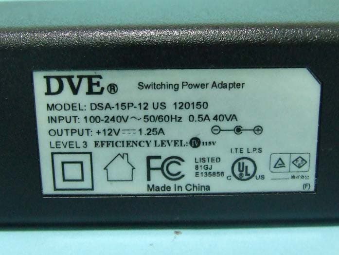
SOY-HAW2R1
Feb 09, 2011Hi-Gain Wireless-N Dual Radio Smart Repeater Pro
Equipment Class
DTS - Digital Transmission System
SOY-HAWNU2
Sep 15, 2010Hi-Gain Wireless-150N Windows Adapter with Range Amplifier
Equipment Class
DTS - Digital Transmission System