SQB-NIVISAN00102.4 GHz Ainode
HDJ WIRELESS ENTERPRISE, LLC d/b/a NIVIS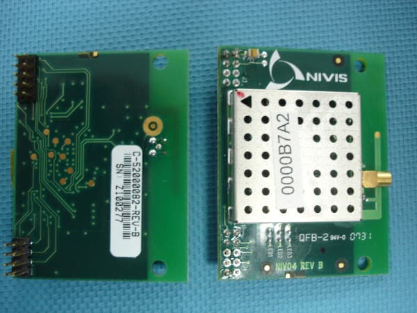
Click to zoom
Application Details
- Equipment Class
- DTS - Digital Transmission System
- Date of Grant
- Mar 27, 2008
- Application Purpose
- Original Equipment
- Date of Application
- Mar 27, 2008
- Equipment Note
- 2.4 GHz Ainode
- Frequency Range
- 2405.00000000 - 2480.00000000
- Country
- United States
Documents & Files
Document Text
Text extracted from the exhibit documents filed with the FCC. Open a document above to read the original.
Users Manual
2.4GHz RF Modem User’s Manual Version 1.0 Modified: August 2, 2007 User Manual Proprietary & Confidential Version 1.1 Revision History Date Revision Description Author 02/08/2007 1.0 Document Creation Szabolcs Zigovszki User Manual Proprietary & Confidential Version 1.1 Table of Contents 1. Purpose and Scope of Document......................................................................... 1 2. Overview of the Radio Modem Hardware............................................................. 1 3. Operation of the Nivis Radio Modem ................................................................... 4 3.1. Getting started ...................................................................................................... 4 3.2 Read Calibration EEPROm ...................................Error! Bookmark not defined. 3.3 Transmission .........................................................Error! Bookmark not defined. 3.4 Reception ..............................................................Error! Bookmark not defined. 3.5 Modify Register Values ..........................................Error! Bookmark not defined. 3.6 Additional Features................................................Error! Bookmark not defined. 4. RF Exposure Limit Warning ..................................................................................... 8 5. Compliance Statement (Part 15.19) ......................................................................... 8 6. OEM Responsibility to the FCC Rules and Regulations ........................................ 8 7. Warning (Part 15.21).................................................................................................. 9 User Manual Proprietary & Confidential Page 1 version 1.0 1. Purpose of Document This document was created in order to provide to the user clear guidelines regarding the usage of the Nivis RF-P9-06-01-01 modem. 2. Overview of the Radio Modem Hardware The 2.4GHz Nivis Radio modem is an 802.15.4 wireless module that allows wireless communication using a standard asynchronous serial data stream. The pin-out of the Nivis radio modem is presented in the figure below. Trace PIFA RF SMA Shield Double row 90 deg bent 2mm connector Mounting Holes for horizontal orientation 1.47 in 1.90 in 1 2 17 18 User Manual Proprietary & Confidential Page 2 version 1.0 The radio modem consists of three functional entities: 1. Transceiver section – processor, RF transceiver 2. RF section – BALUNs,RF PA, RF filter, RF switch 3. Non-volatile storage – Eeprom Power is supplied to the modem through pins 1 and 2. Pin 1 must be supplied with 3.3 Volts and powers the digital and RF functional entities of the modem. The modem has internal filtering circuitry to smooth out the supply voltage but it has no onboard regulators. All of the remaining pins of the modem are I/O lines of the processor. The voltage on any of the I/O lines should never exceed 3.3 V. Pins 13 and 14 are the TX and RX pins of UART 1, pins 11 and 12 are the TX and RX of UART2. If connecting to the serial port of a PC, a level-shifting transceiver must be employed in order to provide the appropriate voltage levels on the RX and TX lines. User Manual Proprietary & Confidential Page 3 version 1.0 A table of the radio modem pins is provided below, describing the purpose and functionality of the pins and the max voltage range on the pins. Pin number Pin name Function of pin Nominal voltage Max voltage 1 VCC Voltage supply 3.3 V 3.6 V 2 GND Ground pin 0 V 0 V 3 RST RESET, active low 3.3V 3.6V 4 BKGD DEBUG line 3.3 V 3.6 V 5 KBD5 PTA5, GPIO1, Interrupt capable 3.3 V 3.6 V 6 VREFH Voltage reference pin 2.5V 3.3 V 7 KBD7 PTA7, GPIO3, Interrupt capable 3.3 V 3.6 V 8 KBD6 PTA6, GPIO2, Interrupt capable 3.3 V 3.6 V 9 SCL SCL line of I2C bus 3.3 V 3.6 V 10 SDA SDA line of I2C bus 3.3 V 3.6 V 11 TXD2 TX line of UART 2 3.3 V 3.6 V 12 RXD2 RX line of UART 2 3.3 V 3.6 V 13 TXD1 TX line of UART 1 3.3 V 3.6 V 14 RXD1 RX line of UART 1 3.3 V 3.6 V 15 ADC2 PTB2, ADC input 3.3 V 3.6 V 16 ADC3 PTB3, ADC input 3.3 V 3.6 V 17 ADC1 PTB1, ADC input 3.3 V 3.6 V 18 ADC0 PTB0, ADC input 3.3 V 3.6 V User Manual Proprietary & Confidential Page 4 version 1.0 3. Operation of the Nivis Radio Modem Communication with the NIVIS radio modem happens through serial port 2. The baudrate is set to be 19200, 8N1. 3.1. Getting started Open a terminal software on a serial port with the above settings and connect to the RF modem. Any command is single line followed by enter command. Format of command is: command param1 param2 ... <enter> At startup pushing the enter key a few times is necessary until the reception of the prompt string. PTS Commands description: 1. Clear screen a. Description: clear screen b. Command name: “cls” c. Parameters: None d. Ex: cls<enter> 2. Help a. Description: display commands list and a short description of each command b. Command name: “help” c. Parameters: None d. Ex: help<enter> 3. Read ADC (ATD) channels a. Description: read and display ADC channels values b. Command name: “getadc” c. Parameters: None d. Ex: getadc<enter> 4. Get Modem SPI Register a. Description: get value for a modem register (from page0) b. Command name: “getreg” c. Parameters: 1 User Manual Proprietary & Confidential Page 5 version 1.0 - register ID: hex format d. Ex: getreg 00<enter> 5. Set Modem SPI Register a. Description: set value for a modem register (from page0) b. Command name: “setreg” c. Parameters: 2 - register ID: hex format - register vlaue: hex format d. Ex: setreg 20 80FF<enter> 6. Set Power Amplification value a. Description: set value for a modem PA power (not persistent value) b. Command name: “setpa” c. Parameters: 1 - PA value: hex format d. Ex: setpa FC<enter> 7. Set Modem Channel a. Description: set value for a modem channel (not persistent value) b. Command name: “setch” c. Parameters: 1 - channel number: decimal format d. Ex: setch 0<enter> 8. Set red LED value a. Description: set red LED on or off b. Command name: “s…
Text truncated - open the document above for the full version.
Cover Letter(s)
J1Nrvrs AGENCY AGREEMENT Federal Communications Commission P.O. Box 429 Columbia, MD 21045 Date: October 24.2007 Gentlemen: By signature below, we hereby appoint United States Technologies, Inc. (U.S. Tech) to act as our agent with regard to all FCC equipment authorizations. This appointment will remain in effect until otherwise notifi ed. I further certify by signature below that no party (pter 47 CFR I.2002(b)) to the application is subject to a denial of Federal benefits, including FCC benefits, pursuant to Sectiott i:Ot of the Anti-Drug Abuse Act of 1988, 21 U.S.C. 853(a). This appointment includes the authority to complete FCC Form 731 on our behalf and sign the application as an authonzed agent. Name: Marius Chilom Signature: Title: CEO Date: dc/ tf,/a> + & *t t * TD r! u a tt ,t, tb r| o o g rg o - lOOO CIRCLE 75 PARKWAY O SUITE 3OO * #&.@ . +,s.:. ,r.r" ##;' "* ';"i! ,. "" rB@ W.j ..* s.s$.. $s#. ',..;t w ffi- . ATLANTA, GA 30339 . 678.202.6800
Cover Letter(s)
Confidentiality Request American TCB 6731 Whittier Ave. McLean, VA 22101 FCC ID: SQB-NIVISAN0010 With regards to the exhibits submitted in support of the application for FCC ID: SQB-NIVISAN0010, please classify the following as confidential under the provision of 47 CFR 0.459: • Schematics • Block diagram • Theory of Operation These exhibits contain technical information that NIVIS, LLC deems to be sensitive and proprietary. Therefore this information cannot be published. If this information were to be made public it could be used to the disadvantage of the applicant in the marketplace. Alan Ghasiani US Tech (Authorized Agent for NIVIS, LLC) 3505 Francis Circle Alpharetta, GA 30004 PH: 770-740-0717 Fax: 770-740-1508 www.ustech-lab.com
Cover Letter(s)
March 5, 2008 Douglas E. Noble Examining Engineer ATCBI 6731 Whitttier Ave., McClean, VA 22101 . RE: FCC ID: SQB-NIVISAI0010, Response To Comments of February 26, 2008 Dear Mr. Noble: In response to your comments regarding the above referenced FCC ID: 1. Label is still being done on the MODULE as if this is a modular approval. CORRECT LABEL HAS BEEN UPLOADED. 2. Outside Labeling states that the device contains TX Module. If not modularly approved, this is incorrect. LABEL HAS BEEN CORRECTED. 3. Outside Label should also show co-located contains TX module for the OTHER co-located module. If this is not a modular approval then this question goes away. THIS IS NOT A MODULAR APPROVAL. 4. Internal Photos...: ADDITIONAL PHOTOGRAPHS HAVE BEEN UPLOADED. 5. Confidentiality only request on block diagram and schematics. The Theory of Operation shows some of the block diagrams. Additionally, test report shows theory of operation. There are still various concerns on how to handle confidentiality. PLEASE MAKE THE THEORY OF OPERATION CONFIDENTIAL. WE HAVE ADDED THIS TO THE CONFIDIENTIALITY REQUEST AND DELETED THE THEORY OF OEPRATION FROM THE TEST REPORT. Best Regards, Sandi McEnery US Tech Agent for Nivis LLC
External Photos
US TECH FCC ID: SQB-NIVISAN0010 Test Report Type: FCC Spread Spectrum Radio Report Number: 07-0245 Issue Date: 27 December 2007 Customer: Nivis, LLC Model: 2.4 GHz Ainode Page 67 of 79 Figure 34. Photograph Top and Bottom of 2.4 GHz module
ID Label/Location Info
REVISIONS REVSION DESCRIPTION DATE APPROVED 1. MATERIAL: .002” THICK POLYESTER WITH 3M #400 OR #7921 ACRYLIC ADHESIVE a. BACKING: SILICONE RELEASE LINER b. FACE COLOR: WHITE WITH BLACK INK 2. ENVIRONMENTAL: a. TEMPERATURE RANGE: -40 º C TO +85 º C b. ADHESIVE, MATERIAL AND INK SHALL BE RESISTANCE TO UV DEGRADATION c. LIGHT AND HUMIDITY AS SPECIFIED IN UL 969 – OUTDOOR EXPOSURE TEST 3. FONT: MODEL ID AND FCC ID ARIAL 9 BOLD AND TEXT ARIAL 8 4. LABEL SIZE: 1.50” WIDE X 0.75” HIGH DRAWN BY: C.ENE DATE: 11/28/07 APPROVALS NIVIS LLC. ATLANTA , GEORGIA DOC CONTROL: DATE: TITLE: PURCH’G: DATE: DEV ENG: DATE: QUAL ASSR: DATE: Product Label, FCC 2.4GHz AiNODE MFG ENG: DATE: SIZE A FCSM NO. DWG. NO. 900 REV. 1 PRODUCT MGR: DATE: SCALE: NONE SHEET: 1 SPECIFICATION CONTROL FCC ID: SQB-NIVISAN0010 MODEL ID: NIVISAN 0010 THIS DEVICE COMPLIES WITH PART 15 OF THE FCC RULES. OPERATION IS SUBJECT TO THE FOLLOWING TWO CONDITIONS. (1) THIS DEVICE MAY NOT CAUSE HARMFUL INTERFERENCE, AND (2) THIS DEVICE MUST ACCEPT ANY INTERFERENCE RECEIVED, INCLUDING INTERFERENCE THAT MAY CAUSE UNDESIRED OPERATION. US TECH FCC ID: SQB-NIVISAN0010 Test Report: FCC Spread Spectrum Radio Report Number: 07-0245 Issue Date: 27 December 2007 Customer: Nivis, LLC Model: 2.4 GHz Ainode 2.4 GHZ AINODE LABEL WILL BE LOCATED ON TOP OF THE RF SHIELD
ID Label/Location Info
REVISIONS REVSION DESCRIPTION DATE APPROVED SPECIFICATION CONTROL 1. MATERIAL: .002” THICK POLYESTER WITH 3M #400 OR #7921 ACRYLIC ADHESIVE a. BACKING: SILICONE RELEASE LINER b. FACE COLOR: WHITE WITH BLACK INK 2. ENVIRONMENTAL: a. TEMPERATURE RANGE: -40 º C TO +85 º C b. ADHESIVE, MATERIAL AND INK SHALL BE RESISTANCE TO UV DEGRADATION c. LIGHT AND HUMIDITY AS SPECIFIED IN UL 969 – OUTDOOR EXPOSURE TEST 3. FONT: MODEL ID AND FCC ID ARIAL 9 BOLD AND TEXT ARIAL 8 4. LABEL SIZE: 1.50” WIDE X 0.75” HIGH FCC ID: SQB-NIVISAN0010 MODEL ID: NIVISAN 0010 Also contains FCC ID: PY76220501-BV THIS DEVICE COMPLIES WITH PART 15 OF THE FCC RULES. OPERATION IS SUBJECT TO THE FOLLOWING TWO CONDITIONS. (1) THIS DEVICE MAY NOT CAUSE HARMFUL INTERFERENCE, AND (2) THIS DEVICE MUST ACCEPT ANY INTERFERENCE RECEIVED, INCLUDING INTERFERENCE THAT MAY CAUSE UNDESIRED OPERATION. DRAWN BY: C.ENE DATE: 11/28/07 APPROVALS NIVIS LLC. ATLANTA , GEORGIA DOC CONTROL: DATE: TITLE: PURCH’G: DATE: DEV ENG: DATE: QUAL ASSR: DATE: Product Label, FCC 2.4GHz AiNODE MFG ENG: DATE: SIZE A FCSM NO. DWG. NO. 900 REV. 1 PRODUCT MGR: DATE: SCALE: NONE SHEET: 1
Internal Photos
US TECH FCC ID: SQB-NIVISAN0010 Test Report: FCC Spread Spectrum Radio Report Number: 07-0245 Issue Date: 27 December 2007 Customer: Nivis, LLC Model: 2.4 GHz Ainode Front View of Nivis Module Board, with Shield US TECH FCC ID: SQB-NIVISAN0010 Test Report: FCC Spread Spectrum Radio Report Number: 07-0245 Issue Date: 27 December 2007 Customer: Nivis, LLC Model: 2.4 GHz Ainode Front View of Nivis Module Board, without Shield US TECH FCC ID: SQB-NIVISAN0010 Test Report: FCC Spread Spectrum Radio Report Number: 07-0245 Issue Date: 27 December 2007 Customer: Nivis, LLC Model: 2.4 GHz Ainode Back View of Nivis Module Board US TECH FCC ID: SQB-NIVISAN0010 Test Report: FCC Spread Spectrum Radio Report Number: 07-0245 Issue Date: 27 December 2007 Customer: Nivis, LLC Model: 2.4 GHz Ainode Front View of Internal Boards US TECH FCC ID: SQB-NIVISAN0010 Test Report: FCC Spread Spectrum Radio Report Number: 07-0245 Issue Date: 27 December 2007 Customer: Nivis, LLC Model: 2.4 GHz Ainode Front View of Internal Boards US TECH FCC ID: SQB-NIVISAN0010 Test Report: FCC Spread Spectrum Radio Report Number: 07-0245 Issue Date: 27 December 2007 Customer: Nivis, LLC Model: 2.4 GHz Ainode Front View of Internal Boards US TECH FCC ID: SQB-NIVISAN0010 Test Report: FCC Spread Spectrum Radio Report Number: 07-0245 Issue Date: 27 December 2007 Customer: Nivis, LLC Model: 2.4 GHz Ainode Front View of Internal Boards US TECH FCC ID: SQB-NIVISAN0010 Test Report: FCC Spread Spectrum Radio Report Number: 07-0245 Issue Date: 27 December 2007 Customer: Nivis, LLC Model: 2.4 GHz Ainode Front View of Internal Boards US TECH FCC ID: SQB-NIVISAN0010 Test Report: FCC Spread Spectrum Radio Report Number: 07-0245 Issue Date: 27 December 2007 Customer: Nivis, LLC Model: 2.4 GHz Ainode Back View of Internal Boards US TECH FCC ID: SQB-NIVISAN0010 Test Report: FCC Spread Spectrum Radio Report Number: 07-0245 Issue Date: 27 December 2007 Customer: Nivis, LLC Model: 2.4 GHz Ainode Back View of Internal Boards US TECH FCC ID: SQB-NIVISAN0010 Test Report: FCC Spread Spectrum Radio Report Number: 07-0245 Issue Date: 27 December 2007 Customer: Nivis, LLC Model: 2.4 GHz Ainode Back View of Internal Boards US TECH FCC ID: SQB-NIVISAN0010 Test Report: FCC Spread Spectrum Radio Report Number: 07-0245 Issue Date: 27 December 2007 Customer: Nivis, LLC Model: 2.4 GHz Ainode US TECH FCC ID: SQB-NIVISAN0010 Test Report: FCC Spread Spectrum Radio Report Number: 07-0245 Issue Date: 27 December 2007 Customer: Nivis, LLC Model: 2.4 GHz Ainode US TECH FCC ID: SQB-NIVISAN0010 Test Report: FCC Spread Spectrum Radio Report Number: 07-0245 Issue Date: 27 December 2007 Customer: Nivis, LLC Model: 2.4 GHz Ainode US TECH FCC ID: SQB-NIVISAN0010 Test Report: FCC Spread Spectrum Radio Report Number: 07-0245 Issue Date: 27 December 2007 Customer: Nivis, LLC Model: 2.4 GHz Ainode US TECH FCC ID: SQB-NIVISAN0010 Test Report: FCC Spread Spectrum Radio Report Number: 07-0245 Issue Date: 27 December 2007 Customer: Nivis, LLC Model: 2.4 GHz Ainode US TECH FCC ID: SQB-NIVISAN0010 Test Report: FCC Spread Spectrum Radio Report Number: 07-0245 Issue Date: 27 December 2007 Customer: Nivis, LLC Model: 2.4 GHz Ainode US TECH FCC ID: SQB-NIVISAN0010 Test Report: FCC Spread Spectrum Radio Report Number: 07-0245 Issue Date: 27 December 2007 Customer: Nivis, LLC Model: 2.4 GHz Ainode US TECH FCC ID: SQB-NIVISAN0010 Test Report: FCC Spread Spectrum Radio Report Number: 07-0245 Issue Date: 27 December 2007 Customer: Nivis, LLC Model: 2.4 GHz Ainode Radio Close up
Operational Description
Theory of Operation A functional block diagram for the Nivis RF module is shown on the following page. This module is a direct sequence spread spectrum transceiver operating in the 2400 – 2483.5 MHz ISM band. The system is based on the IEEE 802.15.4 standard, with channels spaced at 5 MHz intervals in the ISM band. The system operates at a chip rate of 2 Mcps, a symbol rate of 62.5 kbps, and a bit rate of 250kbps. O-QPSK modulation is used with 16-ary orthogonal symbols. An input supply of 3.3 VDC is supplied to the RF module using a two stage supply. Specifically, this supply consists of a switching regulator followed by linear regulator. The input range of this supply is 105-305 VAC. The module transmits with a maximum power of +22 dBm into an external ¼ wave whip antenna. This module does not transmit for more than 10 ms over any 125 ms time period. The receiver is a low-IF receiver. The received RF signal is amplified by a low noise amplifier and down-converted to a 1 st IF of 65MHz and then down- converted in quadrature (I and Q) to the intermediate frequency (IF) of 1 MHz. The digital back end performs Differential Chip Detection; the correlator de- spreads the Direct Sequence Spread Spectrum O-QPSK signal, determines the symbols and packets, and detects the data.
RF Exposure Info
US TECH FCC ID: SQB-NIVISAN0010 Test Report Type: FCC Spread Spectrum Radio Report Number: 07-0245 Issue Date: 27 December 2007 Customer: Nivis, LLC Model: 2.4 GHz Ainode Page 61 of 79 2.16 Maximum Public Exposure to RF (MPE) The maximum exposure level to the public from the RF power of the RUT shall not exceed a power density, S, of 1 mW/cm 2 at a distance, d, of 20 cm from the EUT. Therefore, for : Peak Power (Watts) = 0.186 (from paragraph 2.6, herein) Gain of Transmit Antenna = 5dB I = 3.16 numeric (Paragraph 2.5, herein) Distance = 20 cm S = (PG/ 4πd 2 ) = EIRP/4A Where: A = The area of the circle of radius d = 20cm. = 0.186x3.16 / 4x3.14 x (20) 2 = 0.59/5026 = 0.117 mW/cm 2 which is well below the limit.
Test Report
Page 1 of 87 Application for Nivis, LLC FCC Part 15 Certification For the 2.4 GHz Ainode FCC ID: SQB-NIVISAN0010 UST Project: 07-0245 Issue Date: December 27, 2007 Total number of pages contained in this report: _86 3505 Francis Circle Alpharetta, GA 30004 PH: 770-740-0717 Fax: 770-740-1508 www.ustech-lab.com Page 2 of 87 I certify that I am authorized to sign for the manufacturer and that all of the statements in this report and in the Exhibits attached hereto are true and correct to the best of my knowledge and belief: US TECH (AGENT RESPONSIBLE FOR TEST): By: Name: Alan Ghasiani Title: Operations & Engineering Date: December 27, 2007 Nivis, LLC 1000 Circle 75 Parkway Atlanta, GA 30339 By: Name: Title: Date: This report shall not be reproduced except in full. This report may be copied in part only with the prior written approval of U.S. Technologies. The results contained in this report are subject to the adequacy and representative character of the sample provided. 3505 Francis Circle Alpharetta, GA 30004 PH: 770-740-0717 Fax: 770-740-1508 www.ustech-lab.com US TECH FCC ID: SQB-NIVISAN0010 Test Report: FCC Spread Spectrum Radio Report Number: 07-0245 Issue Date: 27 December 2007 Customer: Nivis, LLC Model: 2.4 GHz Ainode Page 3 of 87 Table Of Contents Paragraph Title Page 1. General Information 7 1.1 Product Description 7 1.2 Related Submittal(s) 7 2. Tests And Measurements 8 2.1 Configuration of Tested EUT 8 2.2 Test Facility 8 2.3 Test Equipment 8 2.4 Modifications 8 2.5 Antenna Description 15 2.6 Peak Power (Band edge Antenna Conducted at Antenna Terminal) 16 2.7 Antenna Conducted Spurious Emissions 21 2.8 Peak Radiated Spurious Emissions and Average Radiated 35 Spurious Emissions 2.8.1 Worst – Case Transmit Duty Cycle for 2.4 GHz Ainode 35 2.9 Band Edge Requirements 42 2.9.1 Lower Band Edge 42 2.9.2 Upper Band Edge 42 2.10 Minimum 6 dB Bandwidth 45 2.11 Average Time of Occupancy per Channel 50 2.12 Power Line Conducted for Digital Device & Receiver 52 2.13 Power Line Conducted Emissions for Transmitter 53 2.14 Radiated Emissions for Digital Device & Receiver 55 2.15 Peak Power Spectral Density 57 2.16 Maximum Public Exposure to RF Radiation (MPE) 61 2.17 Co-Located Transmitter 62 3. Labeling Information 61 4. Block Diagram(s)/ Schematic(s) 63 4.1 Ainode RF Module Block Diagram 64 4.2 Schematic Diagram 65 5. Photographs 66 5.1 Photos of Tested EUT 66 6. Theory of Operation 75 7. User's Manual 76 US TECH FCC ID: SQB-NIVISAN0010 Test Report: FCC Spread Spectrum Radio Report Number: 07-0245 Issue Date: 27 December 2007 Customer: Nivis, LLC Model: 2.4 GHz Ainode Page 4 of 87 List Of Figures Figure Title Page 1 Test Configuration 9 2 Photograph(s) of Spurious Emissions Measurement (Front) 12 3 Photograph(s) of Spurious Emissions Measurement (Rear) 13 4 Photographs of Conducted Emissions Measurement 14 5 Peak Power per FCC Section 15.247 (b) Low Channel 18 6 Peak Power per FCC Section 15.247 (b) Mid Channel 19 7 Peak Power per FCC Section 15.247 (b) High Channel 20 8 Antenna Conducted Spurious Emissions 15.247 (c) Low 22 9 Antenna Conducted Spurious Emissions 15.247 (c) Low (Cont’d) 23 10 Antenna Conducted Spurious Emissions 15.247 (c) Low (Cont’d) 24 11 Antenna Conducted Spurious Emissions 15.247 (c) Low (Cont’d) 25 12 Antenna Conducted Spurious Emissions 15.247 (c) Low (Cont’d) 26 13 Antenna Conducted Spurious Emissions 15.247 (c) Mid 27 14 Antenna Conducted Spurious Emissions 15.247 (c) Mid (Cont’d) 28 15 Antenna Conducted Spurious Emissions 15.247 (c) Mid (Cont’d) 29 16 Antenna Conducted Spurious Emissions 15.247 (c) Mid (Cont’d) 30 17 Antenna Conducted Spurious Emissions 15.247 (c) High 31 18 Antenna Conducted Spurious Emissions 15.247 (c) High (Cont’d) 32 19 Antenna Conducted Spurious Emissions 15.247 (c) High (Cont’d) 33 20 Antenna Conducted Spurious Emissions 15.247 (c) High (Cont’d) 34 21 Peak Radiated Spurious Emissions 15.209 (c) Fundamental Low 37 22 Peak Radiated Spurious Emissions 15.209 (c) Fundamental Mid 38 23 Peak Radiated Spurious Emissions 15.209 (c) Fundamental High 39 24 Peak Radiated Spurious Emissions 15.209 (c) Representative Harmonic Plot 40 25 Band Edge per FCC Section 15.247 (a)(1)(iii) Low 43 26 Band edge per FCC Section 15.247 (a)(1)(iii) High 44 27 Minimum Six dB bandwidth Section 15.247 (a)(2) – Low 47 28 Minimum Six dB Bandwidth Section 15.247 (a)(2) - Mid 48 29 Minimum Six dB Bandwidth Section 15.247 (a)(2) – High 49 30 Pulse Duration for Average Time of Occupancy 51 31 Peak Power Spectral Density 15.247 (a)(1) Low Channel 58 32 Peak Power Spectral Density 15.247 (a)(1) Mid Channel 59 33 Peak Power Spectral Density 15.247 (a)(1) High Channel 60 34 Ainode Card module 62 35 Sony/Ericsson Module 63 36 Module w/Display Window 64 37 Bottom of Case 65 38 Top of Case 66 39 Front of Equipment Case 67 40 Side view of Equipment Case 68 41 Top and Bottom of 2.4 GHz Module 69 US TECH FCC ID: SQB-NIVISAN0010 Test Report: FCC Spread Spectrum Radio Report Number: 07-0245 Issue Date: 27 December 2007 Customer: Nivis, LLC Model: 2.4 GHz Ainode Page 5 of 87 LIST OF TABLES Table Title Page 1. EUT and Peripherals 10 2. Test Instruments 11 3. Antenna Supplied with Ainode 15 4. Peak Power Output 17 5. Peak Radiated Spurious Emissions 36 6. Average Radiated Spurious Emissions 37 7. Six dB Bandwidth 46 8. Conducted Emissions Data, Class B 54 9. Radiated Emissions Data, Class B 56 US TECH FCC ID: SQB-NIVISAN0010 Test Report Type FCC Spread Spectrum Radio Report Number: 07-0245 Issue Date: 27 December 2007 Customer: Nivis, LLC Model: 2.4 GHz Ainode Page 6 of 87 MEASUREMENT/TECHNICAL REPORT Manufacturers Name Nivis, LLC Model Number: 2.4 GHz Ainode FCC ID: SQB-NIVISAN0010 Date: December 27, 2007 This report concerns (check one): Original grant X Class II permissive change_____ Equipment type: 2.4 GHz Spread Spectrum Transceiver Deferred grant requested per 47 CFR 0.457(d)(1)(ii)? yes_____ No X If yes, defer until:_________________ date N.A. agrees to notify the Commission by N.A. …
Text truncated - open the document above for the full version.
Test Setup Photos
US TECH FCC ID: SQB-NIVISAN0010 Test Report Type FCC Spread Spectrum Radio Report Number: 07-0245 Issue Date: 27 December 2007 Customer: Nivis, LLC Model: 2.4 GHz Ainode Page 12 of 79 Figure 2 Photograph(s) for Spurious Emissions Measurement (Front) Test Date: August 16, 2007 UST Project: 07-0245 Customer: Nivis, LLC Model: 2.4 GHz Ainode US TECH FCC ID: SQB-NIVISAN0010 Test Report Type FCC Spread Spectrum Radio Report Number: 07-0245 Issue Date: 27 December 2007 Customer: Nivis, LLC Model: 2.4 GHz Ainode Page 13 of 79 Figure 3 Photograph(s) of Spurious Emissions Measurement (Rear) Test Date: August 16, 2007 UST Project: 07-0245 Customer: Nivis, LLC Model: 2.4 GHz Ainode US TECH FCC ID: SQB-NIVISAN0010 Test Report Type FCC Spread Spectrum Radio Report Number: 07-0245 Issue Date: 27 December 2007 Customer: Nivis, LLC Model: 2.4 GHz Ainode Page 14 of 79 Figure 4 Photograph(S) of Conducted Emissions Measurement Test Date: August 16, 2007 UST Project: 07-0245 Customer: Nivis, LLC Model: 2.4 GHz Ainode
Contact Information
Applicant
Doug Johns
Technical Contact
US TechSteve Sawyer
[email protected]770-740-0717
3505 Francis Circle · Alpharetta, Georgia · United States
Test Firm
US TechGeorge Yang
Technical Specifications
| # | Rule Parts | Frequency Range | Power Output |
|---|---|---|---|
| 1 | 15C | 2.40 GHz - 2.48 GHz | 186.00 mW |
Other Applications from HDJ WIRELESS ENTERPRISE, LLC d/b/a NIVIS
SQB-NIVISMOD0004
May 09, 2011VN210 RF Modem
Equipment Class
DTS - Digital Transmission System
SQB-NIVISNRD20101
Nov 06, 2006RF MODEM Module
Equipment Class
DSS - Part 15 Spread Spectrum Transmitter
SQB-NIVISRN0003
Sep 20, 2006Networking Device
Equipment Class
DSS - Part 15 Spread Spectrum Transmitter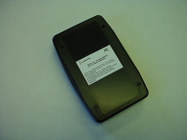
SQB-NIVISSNF0002
May 23, 2006Networking Device
Equipment Class
DSS - Part 15 Spread Spectrum Transmitter
SQB-NIVISP9060101
Jan 03, 2006Transceiver Module
Equipment Class
DSS - Part 15 Spread Spectrum Transmitter