SQB-NIVISMOD0004VN210 RF Modem
HDJ WIRELESS ENTERPRISE, LLC d/b/a NIVIS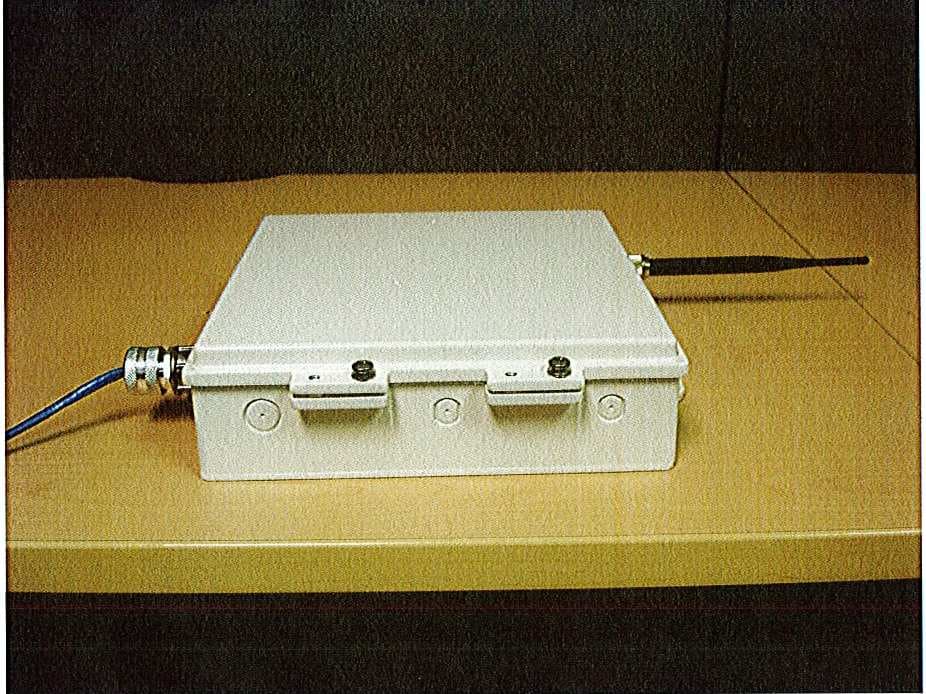
Click to zoom
Application Details
- Equipment Class
- DTS - Digital Transmission System
- Date of Grant
- May 09, 2011
- Application Purpose
- Original Equipment
- Date of Application
- May 09, 2011
- Equipment Note
- VN210 RF Modem
- Frequency Range
- 2405.00000000 - 2475.00000000
- Country
- United States
Documents & Files
Document Text
Text extracted from the exhibit documents filed with the FCC. Open a document above to read the original.
Users Manual
VN210 RF Modem User’s Manual Version 1.2 Created: May 18, 2009 Modified: Sept 2, 2009 User Manual Proprietary & Confidential Version 1.1 Revision History Date Revision Description Author 05/18/2009 1.0 Document Creation Szabolcs Zigovszki 08/24/2009 1.1 Include new antennas Edward Castro 09/02/2009 1.2 Changed section 6 Edward Castro User Manual Proprietary & Confidential Version 1.1 Table of Contents 1. Purpose of Document ............................................................................................ 1 2. Overview of the Radio Modem Hardware ............................................................. 1 3. Operation of the Nivis Radio Modem ................................................................... 4 3.1. Getting started ...................................................................................................... 4 4. RF Exposure Limit Warning ..................................................................................... 4 5. Compliance Statement (Part 15.19) ......................................................................... 4 6. OEM Responsibility to the FCC Rules and Regulations ........................................ 5 7. Warning (Part 15.21) .................................................................................................. 5 User Manual Proprietary & Confidential Page 1 version 1.0 1. Purpose of Document This document was created in order to provide to the user clear guidelines regarding the usage of the VN210 RF modem. 2. Overview of the Radio Modem Hardware The VN210 radio modem is an 802.15.4 wireless module that allows communication using a standard asynchronous serial data stream. The pin-out of the VN210 radio modem is presented in the figure below. User Manual Proprietary & Confidential Page 2 version 1.0 No. Name Description Type Dir Comments 1 UART2-RTS UART2 Request to Send DIG I Can be configured as GPIO 2 UART2-CTS UART2 Clear to Send DIG O Can be configured as GPIO 3 UART2-RXD UART2 Receive Data DIG I Can be configured as GPIO 4 UART2-TXD UART2 Transmit Data DIG O Can be configured as GPIO 5 UART1-RTS UART1 Request to Send DIG I Can be configured as GPIO 6 UART1-CTS UART1 Clear to Send DIG O Can be configured as GPIO 7 UART1-RXD UART1 Receive Data DIG I Can be configured as GPIO 8 UART1-TXD UART1 Transmit Data DIG O Can be configured as GPIO 9 I2C-SDA I2C bus DATA DIG 1 I/O Can be configured as GPIO 10 I2C-SCL I2C bus CLOCK DIG 1 I/O Can be configured as GPIO 11 TMR1 Timer 1 I/O DIG I/O Can be configured as GPIO 12 TMR0 Timer 0 I/O DIG I/O Can be configured as GPIO 13 SPI-SCK SPI Clock DIG O 2 Can be configured as GPIO 14 SPI-MOSI SPI Data Out DIG O 2 Can be configured as GPIO 15 SPI-MISO SPI Data In DIG I 2 Can be configured as GPIO 16 SPI-SS SPI Slave Select DIG O 2 Can be configured as GPIO 17 GND Ground N/A N/A 18 KBI0 RTC clock out enable / Keyboard interface pin 0 DIG O 19 RTC-FOUT 32768Hz RTC clock out DIG O 20 KBI6 Keyboard interface pin 6 DIG I/O Can be configured as GPIO 21 KBI5 Keyboard interface pin 5 DIG I/O Can be configured as GPIO 22 GND Ground N/A N/A 23 GND Ground N/A N/A 24 GND Ground N/A N/A 25 GND Ground N/A N/A 26 RTC-INT-B RTC wake-up interrupt / Keyboard interface pin 7 DIG O 27 KBI1 Keyboard interface pin 1 DIG I/O Can be configured as GPIO 28 KBI2 Keyboard interface pin 2 DIG I/O Can be configured as GPIO 29 KBI3 Keyboard interface pin 3 DIG I/O Can be configured as GPIO 30 KBI4 Keyboard interface pin 4 DIG I/O Can be configured as GPIO 31 GND Ground N/A N/A 32 ADC3 ADC pin 3 Analog I Can be configured as GPIO 33 ADC2 ADC pin 2 Analog I Can be configured as GPIO 34 ADC1 ADC pin 1 Analog I Can be configured as GPIO User Manual Proprietary & Confidential Page 3 version 1.0 35 ADC0 ADC pin 0 Analog I Can be configured as GPIO 36 ADC2-VREFH ADC2 reference, high pin Analog I Can be configured as GPIO 37 ADC2-VREFL ADC2 reference, low pin Analog I Can be configured as GPIO 38 GND Ground N/A N/A 39 VCC Supply voltage N/A N/A 40 GND Ground N/A N/A 41 RESET RESET pin DIG I 42 JTAG-RTCK JTAG Return Clock / ADC pin 7 DIG O Can be configured as GPIO Can be configured as Analog In 43 JTAG-TDO JTAG Test Data Output DIG O Can be configured as GPIO 44 JTAG-TDI JTAG Test Data Input DIG I Can be configured as GPIO 45 JTAG-TCK JTAG Test Data Input DIG I Can be configured as GPIO 46 JTAG-TMS JTAG Test Mode Select DIG I Can be configured as GPIO 47 GND Ground N/A N/A 48 GND Ground N/A N/A 49 GND Ground N/A N/A 50 RF RF pin Analog I/O 52 GND Ground N/A N/A Notes: 1.) Open collector pin if configured as I2C port 2.) Signal Dir valid if module is configured as SPI Master User Manual Proprietary & Confidential Page 4 version 1.0 Power is supplied to the modem through pins 38, 39 and 40. Pin 39 must be supplied with 2.7 to 3.3 Volts and powers the digital and RF functional entities of the modem. The modem has internal filtering circuitry to smooth out the supply voltage but it has no onboard regulators. All of the remaining pins of the modem are I/O lines of the processor, except for pin 50, which is the RF I/O port. The voltage on any of the I/O lines should never exceed VCC+0.3 V. Pins 1 to 4 are attached to UART 2. Pins 5 to 8 are attached to UART1. If connecting to the serial port of a PC, a level-shifting transceiver must be employed in order to provide the appropriate voltage levels on the RX and TX lines. 3. Operation of the Nivis Radio Modem Communication with the VN210 radio modem happens through serial port 1. The baud- rate is set to be 115200, 8N1. 3.1. Getting started Open a terminal software on a serial port with the above settings and connect to the RF modem. Upon power up, the terminal will display a list of the available commands. 4. RF Exposure Limit Warning To comply with FCC’s RF exposure limits for general population / uncontrolled exposure, the antenna(s) used for this transmitter must be installed to provide a separation distance of at least 20cm from all persons and must not be co-lo…
Text truncated - open the document above for the full version.
Cover Letter(s)
ANlvls' Letter of Agency I appoint Intertek Testing Services NA Inc. to act on our behalf in front of the Federal Communications Commission with respect to all matters relating to certification of equipment under the FCC rules until further notice. I furtlrer certify that no party (as defined in t.2002 of CFR 47, 1995) to rhis application, including myself, is subject to denial of federal benefits, that includes FCC benefits. pursuant to section 5301 of the Anti-Drug Abuse Act of 1988, 2l u.s.c.,853A. Dated this /o day ol-be{_,ZO I O. (ate) ao*- bgaq Signature Name Title Company Telephone lOOO(,lR.|i:l|iPARl(wi\YlIl..jiiiDi::l.OOli
Cover Letter(s)
, t\Nrvrs o I { r+ o r| tr a :I o o rl' 0 o o t! o l.i,rlll ,:,)),t:.: Attention: Application Examiner Re: Request for confidentiality Applicant: NIVIS, LLC FCC ID: SQB-NIVISMOD00O4 To whom it may concern, Pennanent Conftdentiality ,. Request is hereby submitted by NIVIS, LLC to withhold permanently from public review certain portions of the application for equipment certification for the referenced FCC identifiers. This request for confidentiality is made pursuant to 47 CFR 0.457(d) and 0.459 of the FCC Rules. In particular, the following sections of the application are to be kept permanently confidential: o Schematics o Detailed Block diagrams o Detailed Operational/Functional Description o Parts list Short-term Confidentiality Request is hereby submitted by NIVIS, LLC to withhold from public review for a period of 45 days from the date of the Grant of Equipment Authorization and prior to marketing, certain portions of the application for equipment certification for the referenced FCC identifiers. This request for confidentiality is made pursuant to 47 CFR 0.457(d) and 0.459 of the FCC Rules. In particular, the following sections of the application are to be kept confidential for a period of 45 days from the date of Authorization: r External photos o Internal photos o User manual lOOO CIRCLE 75 PARKWAY . SUITE 306(A ATLANTA, GA 30339 . 678.202.6800 i ,.i:ii: iru,,rir riii: lli{ !rNr\rrs Rationale for request for confidentiality: NIVIS, LLC has invesled considerable time and materials in research and development to produce the referenced product, lPermanent confidentiality.' Disclosure of the permanently confidential portions of this application to competitors would not only give them significant competitive advantages in developing similar producis, but would also disclose succpssful implementation of unpublished, leading edge technology developed by us.l[Shor turm confidentiality: Disclosure of the short-term confidential portions of this application during the period of importation and/or distribution would reveal key aspects of proprietary technology to competitors and diminish the value of our investment in research and development.l The fee for confidentiality has been submitted along with the fee for certification.l If you have questions or need further information, please contact the undersigned. Sincerely, o t rt o rl E =, a o rlt 0 o q to q fu,cco{ Horl,Snre_ e.,Ji*&f A),vrs, LL L 2(2) 1000 CIRCLE 75 PARKWAY . SUITE 300 . ATLANTA, GA 30339 o 678.202.6800 ;$g M www*ffi.$$ffiwffiffi*ffiffiffiffi
External Photos
External Photographs
External Photos
External Photographs
ID Label/Location Info
REVISIONS ZONE REV. DESCRIPTION DATE APPROVED A INITIAL RELEASE 6/1/10 P.RIVALDO FCC/IC Label VR900-200 P.RIVALDO ANSI Y14.5.DIMENSIONS & TOLERANCES IN ACCORDANCE WITHLATEST P.RIVALDO Q.A. SCALE:1:1 SIZE A COMMENTS: REV. SHEET 1 OF 1 DATE TWO PLACE DECIMAL NAME A THREE PLACE DECIMAL .005 .1 .015 WRITTEN PERMISSION OF :NIVIS LLC. MFG APPR.ENG APPR.CHECKED DRAWN DIMENSIONS ARE IN INCHESTOLERANCES:FRACTIONALANGULAR: 3 ° BEND ONE PLACE DECIMAL THIS DOCUMENT SUBMITTED INCONFIDENCE CONTAINS PROPRIETARYINFORMATION WHICH SHALL NOT BE REPRODUCED OR TRANSFERRED TOOTHER DOCUMENTS OR DISCLOSED TO OTHERSOR USED FOR MANUFACTURINGOR ANY OTHER PURPOSE WITHOUT PRIOR PROPRIETARY AND CONFIDENTIAL 6/01/10 6/03/10 1. MATERIAL: .002” THICK POLYESTER WITH 3M #400 OR #7921 ACRYLIC ADHESIVE BACKING: SILICONE RELEASE LINERFACE COLOR: WHITE WITH BLACK INK2. ENVIRONMENTAL:TEMPERATURE RANGE: -40ºC TO +85ºCADHESIVE, MATERIAL AND INK SHALL BE RESISTIVE TO UV DEGRADATION LIGHT AND HUMIDITY AS SPECIFIED IN UL 969 - OUTDOOR EXPOSURE TEST 3. FONT: FCC ID:SQB-NIVISMOD0004 AND INDUSTRY CANADA:6546A- NIVISMOD004 ARIAL 4 BOLD AND ALL OTHER TEXT ARIAL 4 2.00 1.00 R 0 . 0 6 4X
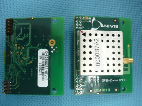
Internal Photos
Internal Photographs
Test Report
Client: Product Designation: VN210 2.4GHz Report Number: 100016744ATL-001 All services undertaken are subject to the following general policy: This report is for the exclusive use of Intertek's Client and is provided pursuant to the agreement between Intertek and its Client. Intertek's responsibility and liability are limited to the terms and conditions of the agreement. Intertek assumes no liability to any party, other than to the Client in accordance with the agreement, for any loss, expense or damage occasioned by the use of this report. Only the Client is authorized to copy or distribute this report and then only in its entirety. Any use of the Intertek name or one of its marks for the sale or advertisement of the tested material, product or service must first be approved in writing by Intertek. The observations and test results in this report are relevant only to the sample tested. This report by itself does not imply that the material, product, or service is or has ever been under an Intertek certification program. This report must not be used to claim product endorsement by A2LA, NIST, or any agency of the US Government. Tested by: Tests performed by:Report reviewed by: Standard: Richard C. Bianco EMC Project Engineer Jeremy O. Pickens EMC Department Engineer Nivis LLC 1000 Circle 75 Parkway 3rd Floor Atlanta, GA 30339 Contact: Dean Carpenter Phone: 678.202.6861 Fax: 678.202.6820 TEST REPORT April 19, 2011 Intertek Testing Services NA Inc. 1950 Evergreen Blvd., Suite 100 Duluth, GA 30096 FCC 15.247 and RSS-210, Issue 7, 2007 Frequency Hopping and Digital Modulation Systems operatin within the bands 902-928 MHz, 2400-2483.5 MHz, and 5725-5850 MHz Page 1 of 24EMC Report for Nivis LLC on the VN210 2.4GHz 04/19/2011Report Number: 100016744ATL-001Issued: Intertek 2.0 Test Summary 1.0 Introduction and Conclusion Test DateTest Full NameResultSection System setup including cable interconnection details, support equipment and simplified block diagram. (System Setup)4.0 Transmitter Information for equipment operating under Parts 11, 15 and 18 of the rules (Transmitter Info - Unlicensed)5.0 02/05/20106dB Bandwidth (6 dB Bandwidth)PASS6.0 02/05/2010FCC Part 15.247(b)(3) / RSS-210 A8.4(4) (Peak Output Power)PASS7.0 02/05/2010FCC Part 15.247(e) / RSS-210 A8.2(2) (Power Spectral Density)PASS8.0 02/05/2010FCC Part 15.247(d) / RSS-210 A8.5 - Conducted (Conducted Spurious Emissions)PASS9.0 02/05/2010FCC Part 15.205 / RSS-210 2.2 (Radiated Band Edge)PASS10.0 Additional provisions to the general radiated emission limitations. (FCC 15C - 15.215)11.0 Revision History (Revision History)12.0 The tests indicated in section 2.0 were performed on the product constructed as described in section 3.0. The remaining test sections are the verbatum text from the actual data sheets used during the investigation. These test sections include the test name, the specified test Method, a list of the actual Test Equipment Used, documentation Photos, Results and raw Data. No additions, deviations, or exclusions have been made from the standard(s) unless specifically noted. Based on the results of our investigation, we have concluded the product tested complies with the requirements of the standard(s) indicated. The results obtained in this test report pertain only to the item(s) tested. Page 2 of 24EMC Report for Nivis LLC on the VN210 2.4GHz 04/19/2011Report Number: 100016744ATL-001Issued: Intertek 3.0 Description of Equipment Under Test Equipment Under Test Description Manufacturer Model Number Serial Number Wireless radio Nivis VN210 NA EUT receive date: 02/03/2010 EUT receive condition: Good Description of EUT provided by Client: The VN210 is an industrial wireless radio that enables users to wirelessly monitor industrial devices. It offers a full API for easy integration with an organization’s devices. From temperature sensors to gas monitors, the VN210 helps an organization unlock valuable information about their operating environment. Description of EUT exercising: The EUT was placed in a transmit state during testing. During radiated emissions testing, the antenna placed on the system was an ANT-N-5 Mini-Box (5.5 dBi). Page 3 of 24EMC Report for Nivis LLC on the VN210 2.4GHz 04/19/2011Report Number: 100016744ATL-001Issued: Intertek System setup including cable interconnection details, support equipment and simplified block diagram. (System Setup) 4.0 Method: Record the details of EUTcabling, document the support equipment, and show the interconnections in a block diagram. Data: EUT AC Mains POE Supply Remote equipment A B Simplified block diagram Drawing: Page 4 of 24EMC Report for Nivis LLC on the VN210 2.4GHz 04/19/2011Report Number: 100016744ATL-001Issued: Intertek System setup including cable interconnection details, support equipment and simplified block diagram. (System Setup) 4.0 A B Description EUT Cabling Connection Length Shielding FerritesIDFromTo EUTPOE Supply POE SupplyAC Mains RJ4510m Power cord1.5mNoNo NoNo Support Equipment DescriptionManufacturerModel NumberSerial Number POE Power Supply Page 5 of 24EMC Report for Nivis LLC on the VN210 2.4GHz 04/19/2011Report Number: 100016744ATL-001Issued: Intertek Transmitter Information for equipment operating under Parts 11, 15 and 18 of the rules (Transmitter I nfo - Unlicensed) 5.0 Method: FCC Rule Part Company Name: Address: P hone: Fax: Contact Name: Email: Company Name: Address: P hone: Fax: Contact Name: Email: FCC ID: EUT Model Number: EUT Serial Number: 2.1033(b)(3) 2.1033(b)(4) 2.1033(b)(5) 2.1033(b)(6) 2.1033(b)(7) 2.1033(b)(1) User Manual Brief description of circuit functions Attach as separate exhibit.Internal and external photographs 2.1033(b)(2) Equipme nt Attach as separate exhibit. Block diagram showing frequency of oscillators Attach as separate exhibit. Test report Incorporated with this document Applicant M anufacture r Nivis LLC 1000 Circle 75 P arkway SE 678-202-6861 678-202-6820 Dean Carpenter [email protected] Nivis LLC Dean Ca…
Text truncated - open the document above for the full version.
Test Report
Client: Product Designation: VersaRouter 800 & 900 Report Number: 100016744ATL-002 All services undertaken are subject to the following general policy: This report is for the exclusive use of Intertek's Client and is provided pursuant to the agreement between Intertek and its Client. Intertek's responsibility and liability are limited to the terms and conditions of the agreement. Intertek assumes no liability to any party, other than to the Client in accordance with the agreement, for any loss, expense or damage occasioned by the use of this report. Only the Client is authorized to copy or distribute this report and then only in its entirety. Any use of the Intertek name or one of its marks for the sale or advertisement of the tested material, product or service must first be approved in writing by Intertek. The observations and test results in this report are relevant only to the sample tested. This report by itself does not imply that the material, product, or service is or has ever been under an Intertek certification program. This report must not be used to claim product endorsement by A2LA, NIST, or any agency of the US Government. Tested by: Tests performed by:Report reviewed by: Standard: Richard C. Bianco EMC Project Engineer Jeremy O. Pickens EMC Department Engineer Nivis LLC 1000 Circle 75 Parkway 3rd Floor Atlanta, GA 30339 Contact: Dean Carpenter Phone: 678.202.6861 Fax: 678.202.6820 TEST REPORT February 28, 2010 Intertek Testing Services NA Inc. 1950 Evergreen Blvd., Suite 100 Duluth, GA 30096 CFR, Title 47, Chapter I, Part 15 Subpart B (USA) ICES-003, Issue 4, 2004 (Canada) Page 1 of 12EMC Report for Nivis LLC on the VersaRouter 800 & 900 02/28/2010Report Number: 100016744ATL-002Issued: Intertek 2.0 Test Summary 1.0 Introduction and Conclusion Test DateTest Full NameResultSection System setup including cable interconnection details, support equipment and simplified block diagram. (System Setup)4.0 02/04/2010Radiated emissions (E-field) (Radiated Emissions)PASS5.0 Conducted emissions on AC power lines (Conducted Emissions) was waived due to the EUT is a POE only device.NA The tests indicated in section 2.0 were performed on the product constructed as described in section 3.0. The remaining test sections are the verbatum text from the actual data sheets used during the investigation. These test sections include the test name, the specified test Method, a list of the actual Test Equipment Used, documentation Photos, Results and raw Data. No additions, deviations, or exclusions have been made from the standard(s) unless specifically noted. Based on the results of our investigation, we have concluded the product tested complies with the requirements of the standard(s) indicated. The results obtained in this test report pertain only to the item(s) tested. Page 2 of 12EMC Report for Nivis LLC on the VersaRouter 800 & 900 02/28/2010Report Number: 100016744ATL-002Issued: Intertek 3.0 Description of Equipment Under Test Equipment Under Test Description Manufacturer Model Number Serial Number Router Nivis LLC VersaRouter 800 & 900 NA EUT receive date: 02/03/2010 EUT receive condition: Good Description of EUT provided by Client: The VR800 and VR900 are all-i n-one routers (VR900 incl udes the enclosure) that include the system/network manager, security manager, integration interface, modbus TCP support and the Nivis Monitor Control System (MCS). The MCS provides real time network and status infor mation about the sensors, gateway, etc. Both routers enable industrial routing of sensor data, enabling customers to easily obtain and manage important data about their operating environment. Description of EUT exercising: The device was communicating data packets while the Transmitter was in standby mode. Page 3 of 12EMC Report for Nivis LLC on the VersaRouter 800 & 900 02/28/2010Report Number: 100016744ATL-002Issued: Intertek System setup including cable interconnection details, support equipment and simplified block diagram. (System Setup) 4.0 Method: Record the details of EUTcabling, document the support equipment, and show the interconnections in a block diagram. EUT AC Mains POE Supply Remote equipment A B Simplified Block Diagram Drawing: Page 4 of 12EMC Report for Nivis LLC on the VersaRouter 800 & 900 02/28/2010Report Number: 100016744ATL-002Issued: Intertek System setup including cable interconnection details, support equipment and simplified block diagram. (System Setup) 4.0 A B POE Power Supply Support Equipment DescriptionManufacturerModel NumberSerial Number NoNo NoNoRJ4510m Power cord1.5m EUTPOE Supply POE SupplyAC Mains Description EUT Cabling Connection Length Shielding FerritesIDFromTo Data: Page 5 of 12EMC Report for Nivis LLC on the VersaRouter 800 & 900 02/28/2010Report Number: 100016744ATL-002Issued: Intertek Radiated emissions (E-field) (Radiated Emissions)5.0 Method: Measurements in the frequency range of 30 MHz to 1000 MHz shall be performed with a quasi-peak detector instrument that meets the requirements of Section One of CISPR 16. Above 1000 MHz, a peak detector shall be used. Peak values converted to average by appying the duty cycle correction factor, when applicable. When an average detector is used, it shall meet the requirements of Section One of CISPR 16. The measuring antenna shall correlate to a balanced dipole. Bandwidths: 30 MHz to 1000 MHz: 120 kHz RBW and 1 MHz VBW Above 1000 MHz: 1 MHz RBW and 3 MHz VBW Measurements of the radiated field are made with the antenna located at a distance of 3 or 10 meters from the EUT. The limit applied to the measurement shall be appropriate for the test distance. The test distance shall be indicated in the results section. The EUT shall be arranged and connected with cables terminated in accordance with the product specification. Exploratory tests should be carried out while varying the cable positions to determine the maximum or near-maximum emission level. During manipulation, cables shall not be placed under or on top…
Text truncated - open the document above for the full version.
Test Setup Photos
02/28/2010Report Number: 100016744ATL-002Issued: Intertek Radiated emissions (E-field) (Radiated Emissions)5.0 Description:Manufacturer:Model:Asset Number:Cal Date:Cal Due: Test Equipment Used: Tile - software profile for radiated and conducted emissions testing. SoftwareTile - EmissionsSW00612/09/200912/09/2010 Results: The sample tested was found to Comply. Test Setup - Front View Photo: Page 7 of 12EMC Report for Nivis LLC on the VersaRouter 800 & 900 02/28/2010Report Number: 100016744ATL-002Issued: Intertek Radiated emissions (E-field) (Radiated Emissions)5.0 Test Setup - Rear View Photo: Page 8 of 12EMC Report for Nivis LLC on the VersaRouter 800 & 900
Contact Information
Applicant
Doug Johns
Technical Contact
Nivis, LLCEdward F Castro
[email protected]678-202-6829
1000 Circle 75 Parkway · Atlanta, Georgia · United States
Non-Technical Contact
IntertekRichard C Bianco
[email protected]678-775-2400
Test Firm
Intertek Testing Services NA Inc.Charles Parker
Technical Specifications
| # | Rule Parts | Frequency Range | Power Output |
|---|---|---|---|
| 1 | 15C | 2.40 GHz - 2.48 GHz | 9.23 mW |
Other Applications from HDJ WIRELESS ENTERPRISE, LLC d/b/a NIVIS
SQB-NIVISAN0010
Mar 27, 20082.4 GHz Ainode
Equipment Class
DTS - Digital Transmission System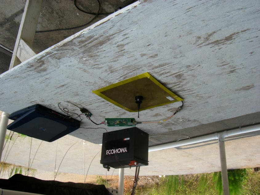
SQB-NIVISNRD20101
Nov 06, 2006RF MODEM Module
Equipment Class
DSS - Part 15 Spread Spectrum Transmitter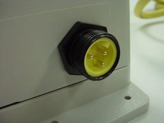
SQB-NIVISRN0003
Sep 20, 2006Networking Device
Equipment Class
DSS - Part 15 Spread Spectrum Transmitter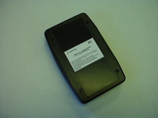
SQB-NIVISSNF0002
May 23, 2006Networking Device
Equipment Class
DSS - Part 15 Spread Spectrum Transmitter
SQB-NIVISP9060101
Jan 03, 2006Transceiver Module
Equipment Class
DSS - Part 15 Spread Spectrum Transmitter