SQB-NIVISSNF0002Networking Device
HDJ WIRELESS ENTERPRISE, LLC d/b/a NIVIS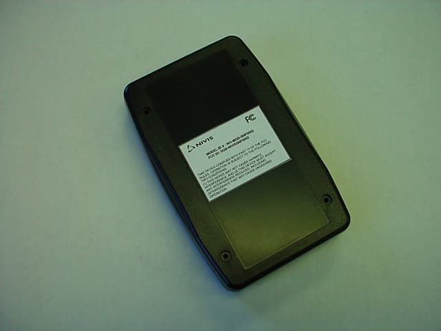
Click to zoom
Application Details
- Equipment Class
- DSS - Part 15 Spread Spectrum Transmitter
- Date of Grant
- May 23, 2006
- Application Purpose
- Original Equipment
- Date of Application
- May 23, 2006
- Equipment Note
- Networking Device
- Frequency Range
- 910.50000000 - 927.50000000
- Country
- United States
Documents & Files
Document Text
Text extracted from the exhibit documents filed with the FCC. Open a document above to read the original.
Users Manual
RF Sniffer User’s Manual Version 1.1 User Manual Proprietary & Confidential Version 1.1 Revision History Date Revision Description Author 05/11/2006 1.0 Initial Release Edward Castro 05/16/2006 1.1 Updated/Cleaned Sections Dan Cornescu 05/24/2006 1.2 Updated Section 6 for proper FCC Statement Trae Harrison User Manual Proprietary & Confidential Version 1.1 Table of Contents 1. Purpose and Scope of Document......................................................................... 1 2. Overview of the RF Sniffer .................................................................................... 1 2.0 Block diagram........................................................................................................ 1 2.1 Operation ............................................................................................................... 2 2.1.1 USB Interface block ............................................................................................ 6 2.1.2 Battery Charger block ......................................................................................... 6 2.1.3 Buck / Boost Regulator block.............................................................................. 7 2.1.4 Optional IrDA Interface block .............................................................................. 7 2.1.5 RF modem block................................................................................................. 7 3. Diagnostic Software............................................................................................... 8 3.1. Getting started ...................................................................................................... 8 3.2 Read Calibration EEPROM ................................................................................... 9 3.3 Transmission....................................................................................................... 10 3.4 Reception ............................................................................................................ 10 3.5 Modify Register Values ........................................................................................ 10 3.6 Additional Features.............................................................................................. 11 4. RF Exposure Limit Warning ................................................................................... 11 5. Compliance Statement (Part 15.19)....................................................................... 11 6. Information to the User (Part 15.105)..................................................................... 12 7. Warning (Part 15.21)................................................................................................ 12 User Manual Proprietary & Confidential Page 1 version 1.0 1. Purpose and Scope of Document The purpose of this document is to pr ovide the user with instructions on how to properly operate the RF Sniffer. 2. Overview of the RF Sniffer The RF Sniffer is a 900MHz frequency- hopping self-contained deployme nt tool which provides a link between a device running specially designed software and t he mesh network. It communicates via the 900 MHz Spread Spectrum mesh network and connects to a personal comput er or PDA USB port. The Portable RF Sni ffer is a battery powered device that can be re-charged from the USB port or from an optional AC adapter. 2.0 Block diagram Below you will find the block diagram for t he main functions of this device. User Manual Proprietary & Confidential Page 2 version 1.0 2.1 Operation To use the RF Sniffer one only needs a connection to a USB port (PDA or PC). For limited periods of time the device can operate just by the internal Li -Ion rechargeable battery. When the device is not in use the power should be turned off to the device, then plugged into t he AC Adapter for charging. There are 3 visual indicators (LED’s) on the front panel: User Manual Proprietary & Confidential Page 3 version 1.0 GREEN LED - Battery Charging LED indicator, continuously light, for periods that the device is charging the internal battery. RED LED – Power LED indicator, continuous ly light if power on and the battery is charged enough. As soon as the battery is depleted and need rec harging the LED start FLASHING. BLUE LED – RF Traffic LED Indicator, lights for short periods of time when RF traffic is detected On the left side of the pictur e is USB connector, in the middle-right is t he Power ON/OFF button, right the AC adapter plug. Below is a picture of inte rnal RF Sniffer circuit board User Manual Proprietary & Confidential Page 4 version 1.0 . On the top side of the board (pictured above) you will find t he RF components, (underneath the RF shield), the power supply section and the PCB antenna. The oppos ite side of the board contains the mi crocontroller and digital section as can be seen in the picture below. User Manual Proprietary & Confidential Page 5 version 1.0 The JTAG connector is located below and to t he right of the RF shield on the front si de of the circuit board. This is used for production and debugging purposes, loading firmware etc. User Manual Proprietary & Confidential Page 6 version 1.0 2.1.1 USB Interface block The USB interface uses a serial to USB br idge controller. Device conforms to USB 2.0 standard. This chip is responsible for translating the USB protocol to the seri al protocol used by the microcontroller. Connection to the PC is via a standard USB Mini B connector. The circuit is protected from damaging ESD by using a quad transient voltage suppressor. The USB interface also provides 5 volts fo r charging the internal Li-In battery. 2.1.2 Battery Charger block The device uses a dual input USB / AC Li-Ion battery char ger. This design allows up to 500 mA battery charge current from the AC adapter or up to 200 mA charge current from the USB interface, (supplied by the PC). The programmable charge currents are defined by the values of the two res…
Text truncated - open the document above for the full version.
External Photos
Nivis, LLC Sniffer Module FCC ID#: SQB-NIVISSNF0002 Photo One – External Front View of Sniffer Module Nivis, LLC Sniffer Module FCC ID#: SQB-NIVISSNF0002 Photo Two – External Rear View of Sniffer Module, Showing ID Label Nivis, LLC Sniffer Module FCC ID#: SQB-NIVISSNF0002 Photo Three – External Close up of FCC ID Label
ID Label/Location Info
REVISIONS REVSION DESCRIPTION DATE APPROVED 1 RELEASED FOR PROTOTYPE 05/03/06 1. MATERIAL: .002” THICK POLYESTER WITH 3M #400 OR #7921 ACRYLIC ADHESIVE a. BACKING: SILICONE RELEASE LINER b. FACE COLOR: WHITE WITH BLACK INK 2. ENVIRONMENTAL: a. TEMPERATURE RANGE: -40 º C TO +85 º C b. ADHESIVE, MATERIAL AND INK SHALL BE RESISTANCE TO UV DEGRADATION c. LIGHT AND HUMIDITY AS SPECIFIED IN UL 969 – OUTDOOR EXPOSURE TEST 3. FONT: ARIAL APPROXIMATELY AS SHOWN a. HEIGHT: .050” BOLD, .035 REGULAR 4. LABEL SIZE: 1.00” WIDE X .50” HIGH DRAWN BY: C.ENE/BAA DATE: 05/03/06 APPROVALS NIVIS LLC. ATLANTA , GEORGIA DOC CONTROL: DATE: TITLE: PURCH’G: DATE: DEV ENG: DATE: QUAL ASSR: DATE: GENERIC LABEL, FCC FCC ID: SQB-NIVISSNF002 SNIFFER MODULE MFG ENG: DATE: SIZE A FCSM NO. DWG. NO. 90000121 REV. 1 PRODUCT MGR: DATE: SCALE: NONE SHEET: 1 SPECIFICATION CONTROL
ID Label/Location Info
MODEL ID # : NIV-MOD-SNF0002 FCC ID: SQB-NIVISSNF0002 THIS DEVICE COMPLIES WITH PART 15 OF THE FCC RULES. OPERATION IS SUBJECT TO THE FOLLOWING TWO CONDITIONS. (1) THIS DEVICE MAY NOT CAUSE HARMFUL INTERFERENCE, AND (2) THIS DEVICE MUST ACCEPT ANY INTERFERENCE RECEIVED, INCLUDING INTERFERENCE THAT MAY CAUSE UNDESIRED OPERATION.
Internal Photos
Nivis, LLC Sniffer Module FCC ID#: SQB-NIVISSNF0002 Photo One – Internal Open for Inspection Nivis, LLC Sniffer Module FCC ID#: SQB-NIVISSNF0002 Photo Two – Internal RF Section Nivis, LLC Sniffer Module FCC ID#: SQB-NIVISSNF0002 Photo Three – Internal Close Up of RF Section Nivis, LLC Sniffer Module FCC ID#: SQB-NIVISSNF0002 Photo Four – Internal Nivis, LLC Sniffer Module FCC ID#: SQB-NIVISSNF0002 Photo Five – Internal Nivis, LLC Sniffer Module FCC ID#: SQB-NIVISSNF0002 Photo Six – Internal Nivis, LLC Sniffer Module FCC ID#: SQB-NIVISSNF0002 Photo Seven – Internal
RF Exposure Info
L.S. Compliance, Inc. Page 51 of 52 Test Report Number: 306277 TX TCB Rev. 1 Prepared For: Nivis, LLC The information on this page is provided by the manufacturer. 19. MPE Calculations Base Station Transceiver MPE Calcluation
Test Report
L.S. Compliance, Inc. W66 N220 Commerce Court Cedarburg, WI 53012 262-375-4400 Fax: 262-375-4248 COMPLIANCE TESTING OF : NIVIS Portable RF Sniffer Prepared For: Nivis, LLC Attention: Mr. Trae Harrison 1000 Circle 75 Parkway, 3 rd Floor Atlanta, GA 30339 Test Report Number: 306277 TX TCB Rev. 1 Test Dates: May 9 th – May 12 th , 2006 All results of this report relate only to the items that were tested. This report is not to be reproduced, except in full, without written approval of L. S. Compliance, Inc. L.S. Compliance, Inc. Page 2 of 52 Test Report Number: 306277 TX TCB Rev. 1 Prepared For: Nivis, LLC Table of Contents Section Description Page Index 2 1 L. S. Compliance in Review 3 2 Signature Page 4 3 Product and General Information 5 4 Introduction 5 5 Product Description 6 6 Test Requirements 7 7 Summary of Test Report 8 8 Radiated Emissions Test 8-21 Mode 1 Data: Pages 11-17 - Mode 2 Data: Pages 18-21 - 9 Band-Edge Measurements 22-23 10 Conducted Emissions onto AC Power Line (in Mode 2) 24-28 11 Occupied Bandwidth (In Mode 1) 29-30 12 Power Output 15.247(b)(2) 31-33 13 Spurious Emissions 15.247(d) 34-36 14 Minimum Channel Separation 37-42 15 Channel Occupancy 43-45 16 Equal Channel Usage 46-47 17 Pseudorandom Hopping Pattern 48-49 18 Receiver Synchronization and Receiver Input Bandwidth 50 19 MPE Calculations 51 Appendix A Test Equipment List 52 L.S. Compliance, Inc. Page 3 of 52 Test Report Number: 306277 TX TCB Rev. 1 Prepared For: Nivis, LLC 1. L. S. Compliance In Review L.S. Compliance - Accreditations and Listing’s As an EMC Testing Laboratory, our Accreditation and Assessments are recognized through the following: A2LA – American Association for Laboratory Accreditation Accreditation based on ISO/IEC 17025 : 1999 with Electrical (EMC) Scope of Accreditation A2LA Certificate Number: 1255.01 Federal Communications Commission (FCC) – USA Listing of 3 Meter Semi-Anechoic Chamber based on Title 47 CFR – Part 2.948 FCC Registration Number: 90756 Industry Canada On file, 3 Meter Semi-Anechoic Chamber based on RSS-212 – Issue 1 File Number: IC 3088-A On file, 3 and 10 Meter OATS based on RSS-212 – Issue 1 File Number: IC 3088 U. S. Conformity Assessment Body (CAB) Validation Validated by the European Commission as a U. S. Competent Body operating under the U. S. /EU, Mutual Recognition Agreement (MRA) operating under the European Union Electromagnetic Compatibility –Council Directive 2004/108/EC (formerly 89/336/EEC, Article 10.2) Date of Validation: January 16, 2001 Validated by the European Commission as a U.S. Notified Body operating under the U.S./EU, Mutual Recognition Agreement (MRA) operating under the European Union Telecommunication Equipment – Council Directive 99/5/EC, Annex V. Date of Validation: November 20, 2002 Notified Body Identification Number: 1243 L.S. Compliance, Inc. Page 4 of 52 Test Report Number: 306277 TX TCB Rev. 1 Prepared For: Nivis, LLC 2. Signature Page Prepared By: May 23, 2006 Teresa A. White, Document Coordinator Date Tested By: May 23, 2006 Khairul Aidi Zainal, EMC Engineer Date Approved By: May 23, 2006 Brian E. Petted, VP of Engineering Date L.S. Compliance, Inc. Page 5 of 52 Test Report Number: 306277 TX TCB Rev. 1 Prepared For: Nivis, LLC 3. Product and General Information Manufacturer: Nivis, LLC Date(s) of Test: May 9 th – May 12 th , 2006 Test Engineer(s): √ Aidi Zainal Abtin Spantman Ken Boston Model #: RF-SNF-00-02 Serial #: 0000402F Voltage: 3.6 VDC Operation Mode: Continuous transmit, and ‘Hopping’ mode 4. Introduction Between May 9 th and May 12 th , 2006, a series of Conducted and Radiated RF Emission tests were performed on one sample of the Nivis RF Sniffer, Model Number RF-SNF-00-02, Serial Number 0000402F, here forth referred to as the “Equipment Under Test” or “EUT”. These tests were performed using the procedures outlined in ANSI C63.4-2003 for intentional radiators, and in accordance with the limits set forth in FCC Part 15.247 (Industry Canada RSS-210) for a low power transmitter. These tests were performed by Khairul Aidi Zainal, EMC Engineer at L.S. Compliance, Inc. All Radiated and Conducted RF Emission tests were performed upon the EUT to measure the emissions in the frequency bands described in FCC Title 47 CFR Part 15, including 15.35, 15.209, 15.247 and Industry Canada RSS-210 to determine whether these emissions are below the limits expressed within the standards. These tests were performed in accordance with the procedures described in the American National Standard for methods of measurement of Radio- Noise Emissions from Low-Voltage Electrical and Electronic Equipment in the Range of 9 kHz to 40 GHz (ANSI C63.4-2003). Another document used as a reference for the EMI Receiver specification was the Comite International Special Des Perturbations Radioelectriques (CISPR) Number 16-1, 2003. All tests were performed at L.S. Compliance, Inc., in Cedarburg, Wisconsin, unless otherwise noted. L.S. Compliance, Inc. Page 6 of 52 Test Report Number: 306277 TX TCB Rev. 1 Prepared For: Nivis, LLC 5. Product Description The Portable RF sniffer is a deployment tool which provides a link between a device operating on a specially designed software and mesh network. It communicates via the 900 MHz spread spectrum mesh network and connects to a personal computer or PDA via a USB port. The portable RF sniffer is a self contained, battery powered device that can be recharged from the USB port or from an optional wall adapter. When charging with the wall adapter, the sniffer is turned off and the USB disconnected. Based on the Chipcon CC1020 transceiver IC, the sniffer is a transceiver that operates in the 915 MHz ISM band. The modulation is FSK with the data source being the on-board microprocessor using a baud rate of 9600. The system uses 50 hop channels and an on- board PCB trace F-antenna is the only antenna option available. L.S. Compliance, Inc. Page 7 of 52 Test Report Number: 306277 TX TCB Rev. 1 Prepared For: Nivis, LLC 6. Test Req…
Text truncated - open the document above for the full version.
Test Setup Photos
Nivis Sniffer FCC ID: SQB-NIVISSNF0002 TEST SETUP PHOTOS Page 1 of 4 Photos Taken During Mode 1 Radiated Emission Testing View of the EUT setup in vertical orientation View of the EUT setup in Horizontal orientation Nivis Sniffer FCC ID: SQB-NIVISSNF0002 TEST SETUP PHOTOS Page 2 of 4 Photos Taken During Mode 1 Radiated Emission Testing (continued) View of the EUT setup in Side orientation Nivis Sniffer FCC ID: SQB-NIVISSNF0002 TEST SETUP PHOTOS Page 3 of 4 Photos Taken During Mode 2 Radiated Emission Testing View of the EUT setup in vertical orientation Nivis Sniffer FCC ID: SQB-NIVISSNF0002 TEST SETUP PHOTOS Page 4 of 4 Photo(s) Taken During Conducted Emission Testing Setup for the Conducted Emissions Test
Contact Information
Applicant
Doug Johns
Test Firm
LS Research, LLCRyan Urness
Technical Specifications
| # | Rule Parts | Frequency Range | Power Output |
|---|---|---|---|
| 1 | 15C | 910.5 MHz - 927.5 MHz | 500.00 mW |
Other Applications from HDJ WIRELESS ENTERPRISE, LLC d/b/a NIVIS
SQB-NIVISMOD0004
May 09, 2011VN210 RF Modem
Equipment Class
DTS - Digital Transmission System
SQB-NIVISAN0010
Mar 27, 20082.4 GHz Ainode
Equipment Class
DTS - Digital Transmission System
SQB-NIVISNRD20101
Nov 06, 2006RF MODEM Module
Equipment Class
DSS - Part 15 Spread Spectrum Transmitter
SQB-NIVISRN0003
Sep 20, 2006Networking Device
Equipment Class
DSS - Part 15 Spread Spectrum Transmitter
SQB-NIVISP9060101
Jan 03, 2006Transceiver Module
Equipment Class
DSS - Part 15 Spread Spectrum Transmitter