SQD-6220APU-ABGWLAN CATV Access Point
MTI Co., Ltd.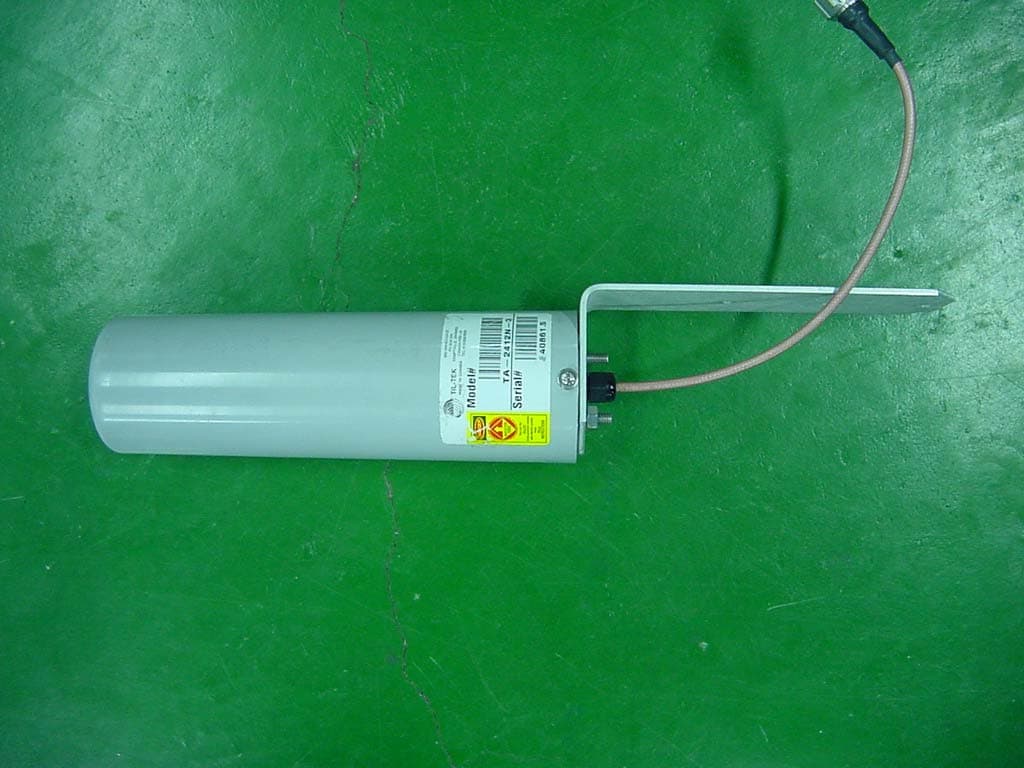
Click to zoom
Application Details
- Equipment Class
- DTS - Digital Transmission System
- Date of Grant
- Jan 17, 2006
- Application Purpose
- Original Equipment
- Date of Application
- Jan 17, 2006
- Equipment Note
- WLAN CATV Access Point
- Frequency Range
- 2412.00000000 - 2462.00000000
- Company
- MTI Co., Ltd.
- Country
- South Korea
Documents & Files
Document Text
Text extracted from the exhibit documents filed with the FCC. Open a document above to read the original.
Users Manual
Nortel Networks WLAN Cable Access Point 6220 User Guide Standard Release 2.0 Issue 1 Dec 2005 What’s inside? About this document Overview Planning your WLAN network Installation Configuration Administration Troubleshooting Appendix NTPM99CA 02 2 Copyright © 2004 Nortel Networks All rights reserved. July 2004. No part of this publication may be reproduced, stored in a retrieval system, or transmitted in any form or by any means, whether electronic, mechanical, photocopying, recording or otherwise without the prior writing of the publisher. Nortel Networks and the Nortel Networks logo are trademarks of Nortel Networks, Inc. Multi-Region Product Documentation This document may describe features that are not available in your region due to local regulations. Compliances Federal Communication Commission Interference Statement This equipment has been tested and found to comply with the limits for a Class B digital device, pursuant to Part 15 of the FCC Rules. These limits are designed to provide reasonable protection against harmful interference in a residential installation. This equipment generates uses and can radiate radio frequency energy and, if not installed and used in accordance with instructions, may cause harmful and, if not installed and used in accordance with instructions, may cause harmful interference to radio communications. However, there is no guarantee that the interference will not occur in a particular installation. If this equipment does cause harmful interference to radio or television reception, which can be determined by turning the equipment off and on, the user is encouraged to try to correct the interference by one or more of the following measures: . • Reorient the receiving antenna . • Increase the separation between the equipment and receiver . • Connect the equipment into an outlet on a circuit different from that to which the receiver is connected . • Consult the dealer or an experienced radio/TV technician for help FCC Caution: To assure continued compliance, (example - use only shielded interface cables when connecting to computer or peripheral devices). Any changes or modifications not expressly approved by the party responsible for compliance could void the user’s authority to operate this equipment. This device complies with Part 15 of the FCC Rules. Operation is subject to the following two conditions: (1) This device may not cause harmful interference, and (2) this device must accept any interference received, including interference that may cause undesired operation. The antenna(s) used for this transmitter must be installed to provide a separation distance of at least 20 cm from all persons and must not be co-located or operating in conjunction with any other antenna or transmitter. The transmitted power of the APU and CSU does not exceed 36 dBm. 3 Publication history December 2005 Issue 1. Issued for WLAN Cable Access Point 6220 APU & CSU 5 Contents ABOUT THIS DOCUMENT 7 OVERVIEW 13 I NTRODUCTION 13 P RODUCT DESCRIPTION 15 APU (ACCESS POINT UNIT) 17 CSU (CORPORATE SERVICE UNIT) 22 PLANNING YOUR WLAN NETWORK 25 S ITE SURVEY & PLANNING 25 W IRELESS NETWORK PLANNING 27 INSTALLATION 29 APU INSTALLATION & CONFIGURATION 29 P ROCEDURE 1-1 33 P ROCEDURE 1-2 38 P ROCEDURE 1-3 39 P ROCEDURE 1-4 41 P ROCEDURE 1-5 48 P ROCEDURE 1-6 49 P ROCEDURE 1-7 51 CSU INSTALLATION & CONFIGURATION 53 P ROCEDURE 2-1 54 P ROCEDURE 2-2 56 CONFIGURATION 59 S OFTWARE INSTALLATION (AP CONFIGURATOR) 60 P ROCEDURE 3-1 62 P ROCEDURE 3-2 73 P ROCEDURE 3-3 85 P ROCEDURE 3-4 97 P ROCEDURE 3-5 106 P ROCEDURE 3-6 138 ADMINISTRATION 179 S AVE CONFIGURATION 180 L OAD NEW CONFIGURATION 181 L OAD NEW LICENSE 182 TROUBLESHOOTING 191 5 WLAN Cable Access Point 6220 NTPM99CA 01 Rel 1.0 Issue 3 Dec 2004 APPENDIX A. SPECIFICATION 198 APPENDIX B. DOCSIS SPECIFICATION 207 APPENDIX C. ANTENNA 209 APPENDIX C. ENCLOSURE DIMENSION 215 7 About this document This document describes the system features used in the WLAN Cable Access Point 6220 Release 2.0 Product. Topics covered include the following: • Overview Introduction Product Description APU (Access Point Unit) CSU (Corporate Service Unit) • System Planning Site Survey & Planning Wireless Network Designing • Installation APU Hardware Installation CSU Hardware Installation • Configuration APU in Secure Data Mode (P2P, P2M) CSU in Secure Data Mode (P2P, P2M) Testing Connection between APU and CSU • Advanced Configuration System Administration Tasks Save configuration Edit configuration Load new configuration Upload new license • Troubleshooting 7 WLAN Cable Access Point 6220 NTPM99CA 01 Rel 1.0 Issue 3 Dec 2004 Audience The intended audience for this document includes: • Installers • Technicians • Nnetwork planners • Network & system engineers • Network administrators List of Abbreviations AP Access Point APU Access Point Unit ARP Address Resolution Protocol BPDU Bridge Protocol Data Unit BPSK Binary Phase-Shift Keying CATV Community Antenna Television CM Cable Modem CMTS Cable Modem Termination System CPE Customer Premises Equipment CSU Corporate Service Unit DBPSK Differential Binary Phase-Shift Keying DHCP Dynamic Host Configuration Protocol DOCSIS Data Over Cable Service Interface Specifications DQPSK Differential Quadrature Phase Shift Keying DVM Digital Volt Ohm Meter EAP Extensible Authentication Protocol EIRP Equivalent Isotropic Radiated Power EMI Electromagnetic Interference FCC Federal Communications Commission FCS Frame Check Sequence FTP File Transfer Protocol HFC Hybrid Fiber Coax ICMP Internet Control Message Protocol IEEE Institute of Electrical and Electronics Engineers ISM Industrial Scientific and Medical equipment ISP Internet Service Provider ITU International Telecommunication Union LOS Line of Sight MAC Media Access Control MIB Management Information Base NAS Network Access Server NAT Network Address Translation 8 WLAN Cable Access Point 6220 NTPM99CA 01 Rel 1.0 Issue 3 Dec 2004 NLOS Non Line of Sight NMS Network Management System…
Text truncated - open the document above for the full version.
Users Manual
180 WLAN Cable Access Point 6220 CSU NTPM99CA Rel 2.0 Issue 5 Dec 2005 Saving configuration Saving the current configuration settings to the hardware device is a one- step process: Use this File Menu option to save the base station configuration parameters to the location from which they were read. If the configuration was read from a base station, it will be saved to the CSU from which it was read. If the configuration was read from a file, the modified configuration will be saved back to that file. To import a saved configuration to an CSU, first connect to the base station using Open Remote Config, then use Import Config File. 1. From the File Menu, select Save Config. Figure 5-1 Save Config Menu 2. Click on the ‘Yes’ button Figure 5-2 Confirm Save Config Window 181 WLAN Cable Access Point 6220 CSU NTPM99CA Rel 2.0 Issue 5 Dec 2005 3. The message box will be displayed, as shown below, and then left click on the OK button. Figure 5-3 Reboot Message Dialog Box 4. Just after this saving, APU or CSU will be restarting automatically. Loading new configuration The 'import config file' option enables you to 'copy' the parameter values that you entered to configure the first Secure Data Mode Station to the other units. The “import config file” option enables you to 'copy' the parameter values that you entered to configure the first Secure Data Mode Station to the other units. 1. From the F ile menu, select Open/Config Bin File. Figure 5-4 Open Config/Bin File Menu 182 WLAN Cable Access Point 6220 CSU NTPM99CA Rel 2.0 Issue 5 Dec 2005 2. And the browse window will appear. Figure 5-5 Open Config File Window 3. Select the configuration file in the specific folder, and Click ‘Open’ button, 4. Then, bridge/brouter Configuration Program” screen will appear. Figure 5-6 Confirm Open Config File Dialog Box 5. Left click on the OK button. Uploading Software There are ten steps that must be done to import the .bin file and its corresponding license file. Be sure you have downloaded and know the location of your files before you start. 1. From the F ile menu, select Upload Software, and the browse window will appear. 183 WLAN Cable Access Point 6220 CSU NTPM99CA Rel 2.0 Issue 5 Dec 2005 Figure 5-7 Upload Software Menu 2. Browse to the location of your .bin file, and select it. Figure 5-8 Open binary Window 3. Click on the ‘Open’ button, and the "License Key Setup" screen will appear: 184 WLAN Cable Access Point 6220 CSU NTPM99CA Rel 2.0 Issue 5 Dec 2005 Figure 5-9 License Key Setup Window 4. Click on the "Import License Key" button, and an "Open" dialog box will appear: Figure 5-10 Open License Key Window 5. Select the license file that corresponds to the Ethernet MAC of the unit you are working with. (If you have "Licenses for this MAC address" selected in the file type drop box, only the licenses for the MAC of the current unit will appear.) 6. Click on the ‘Open’ button 185 WLAN Cable Access Point 6220 CSU NTPM99CA Rel 2.0 Issue 5 Dec 2005 Figure 5-11 License key setup window 7. Click on the ‘OK’ button Figure 5-12 Setup window 8. You can see an initial setup windows and then, From the File menu, select upload software as below. 186 WLAN Cable Access Point 6220 CSU NTPM99CA Rel 2.0 Issue 5 Dec 2005 Figure 5-13 Selecting Upload Software Figure 5-14 Enter IP address dialog 9. Enter the IP address of the unit to upload new software binary and Click on the ‘OK’ button. 187 WLAN Cable Access Point 6220 CSU NTPM99CA Rel 2.0 Issue 5 Dec 2005 Figure 5-15 Uploading Confirmation Dialog 1 10. Click on the ‘OK’ button Figure 5-16 Uploading Confirmation Dialog 2 11. Click on the ‘OK’ button Figure 5-17 Uploading Binary Information Dialog Box 12. Click on the ‘OK’ button 13. “Saving ....Please be patient” screen will appear as below 188 WLAN Cable Access Point 6220 CSU NTPM99CA Rel 2.0 Issue 5 Dec 2005 Figure 5-18 Saving software uploading window 14. Click on the ‘OK’ button Figure 5-19 Reboot Message Dialog Box 15. Click on the ‘OK’ button 16. Software Uploading complete. 189 WLAN Cable Access Point 6220 CSU NTPM99CA Rel 2.0 Issue 5 Dec 2005 Reboot a Remote Station(APU and CSU) The Reboot Remote option of the file menu allows you to reboot remote devices if stations get dropped from the network. Please follow the rebooting procedure to reboot a station from a remote location. 1. Select File/Open Remote Config. 2. Enter the IP address and read/write password for the target base station. 3. Once the configuration has been read from bridge, select File/Reboot Remote. 4. The APU or CSU will restart and run startup diagnostics. Note: After approximately 60 seconds, the unit will start bridging operation using the configuration parameters as they were stored in the remote station prior to the Reboot. Note: If you would like to display the configuration file or monitor the unit's performance after a Reboot, you may have to wait until the unit completes the start-up diagnostics. Once the startup diagnostics are complete, the unit can be accessed again. 191 Troubleshooting 192 WLAN Cable Access Point 6220 NTPM99CA 01 Rel 1.0 Issue 3 Dec 2004 1. APU Power cannot be Turned ON. Check that the CATV Power (45VAC ~ 95VAC) is supplied thorough the coaxial line by measuring the AC Voltage Level. If no power signal is detected at the end of the coaxial cable, you should search a problem point on the CATV Network while moving up toward the ONU and UPS Power supply. 2. LED 2(Link 1) is continuously blinking after running a long time and all network entity including APU cannot receive IP address from DHCP server. Measure the RF signal level at the end of the coaxial cable or monitoring port in the APU enclosure. Also check whether or not the RF signal level is beside the range of required signal. If so, adjust the power level by tuning all related network facility to meet the requirements for the operation of the Cable Modem. * Normal Power level (DOCSIS): +15 to -15 dBmV 3. LED 3(Link 2)/LED 4(Radio Link) are turned off. In the AP Co…
Text truncated - open the document above for the full version.
Cover Letter(s)
MTI Co., LTD 166-10 Karak-dong, Songpa-ku Seoul, Korea 138-810 Tel : +82-2-421-4042 Fax: +82-2-421-4043 URL: www.mtico.co.kr Date: October 25, 2005 Compliance Certification Services Certification Division 561F Monterey Road Morgan Hill, CA 95037 To whom it may concern: We, the undersigned, hereby authorize Onetech Corp., to act on our behalf in all manners relating to application for equipment authorization, including signing of all documents relating to these matters. Any and all acts carried out by Onetech Corp. on our behalf shall have the same effect as acts of our own. In authorizing Onetech Corp. as our agent, we still recognize that we are responsible to: a) comply with the relevant provisions of the certification program; b) make all necessary arrangements for the conduct of the evaluation, including provision for examining documentation and access to all areas, records (including internal audit reports) and personnel for the purposes of evaluation (e.g. testing, inspection, assessment, surveillance, reassessment) and resolution of complaints; c) make claims regarding certification only in respect of the scope for which certification has been granted; d) do not use our product certification in such a manner as to bring the Certification Division into disrepute and not make any statement regarding our product certification which the Certification Division may consider misleading or unauthorized; e) upon suspension or cancellation of certification, discontinue use of all advertising matter that contains any reference thereto and return any certification documents as required by the Certification Division; f) use certification only to indicate the products are certified as being in conformity with specified standards; g) endeavor to ensure that no certificate or report nor any part thereof is used in a misleading manner; h) ensure that any reference to our product certification in communication media such as documents, brochures or advertising, complies with the requirements of the Certification Division; i) keep a record of all complaints made known to the us relating to the product’s compliance with requirements of the relevant standard and to make these records available to the Certification Division when requested; j) take appropriate action with respect to such complaints and any deficiencies found in products or services that affect compliance with the requirements for certification; k) document the actions taken. This authorization is valid until further written notice from the applicant. Sincerely Yours, H. S. Byun / Director MTI Co., Ltd. TEL: +82-2-421-4042 (206) FAX: +82-2-404-4043
Cover Letter(s)
1 Helen Zhao Subject:FW: MTI Co., LTd, FCC ID: SQD-6220APU-ABG, Assessment NO.: AN06T5418, Notice#1 From: Y.G. Gwon Sent: Tuesday, January 17, 2006 10:24 PM To: Helen Zhao Subject: Re: MTI Co., LTd, FCC ID: SQD-6220APU-ABG, Assessment NO.: AN06T5418, Notice#1 Dear Helen, Thank you for your kind cooperation. Attached please find a revised test report and antenna specification. If you need more documents and/or comments, please inform me that in detail. > >> Dear Helen, >> >> Regarding, your kind comments, I would like to answer as following. >> >> Question #1: Enclosed please find some files for covering your comments. >> Question #2: Enclosed please find a file for Declaration Letter >> Question #3: Attached is the revised test report. >> Question # 4: The EUT was already pick up by the client and sent the EUT to their overseas buyer. We will make setup photo for future project. Could you please understand this situation. >> Question #5: Attached is the revised test report. >> Question #6: The value on the plot was deleted amplifier's gain using offset function in the spectrum analyzer. We will do not use this function for future project. >> Question #7: Attached is the revised MPE report. >> Question # 8: Attached is the revised manual. >> Question #9: As you know, the antenna port is only one, so the EUT cannot use both antenna at simultaneously. >> >> Best Regards, >> >> Y. G. Gwon >> >> >>> -----Original Message----- >>> From: Compliance Certification Services [mailto:[email protected]] >>> Sent: Thursday, January 12, 2006 10:44 PM >>> Subject: MTI Co., LTd, FCC ID: SQD-6220APU-ABG, Assessment NO.: >>> AN06T5418, Notice#1 >>> >>> >>> Question #1: Please submit the following missing documents: >>> >>> Block Diagram - System >>> Schematics - System >>> Operational Description - Module >>> Agency Authorization Letter >>> >>> Question #2: The test report indicates the device uses a certified module FCC ID: MXF-M930907, but disables 5150- 2 5350MHz and turbo mode with Firmware, please submit attestation statement in applicant's letterhead. >>> >>> Question #3: The test report indicates power line conducted emisson test is not applicable, "because the EUT shall be operated by DC Voltage and does not connected to public mains network directly". But line conduction test data in the test report and test setup photos were provided in the filing, please explain. >>> >>> Question #4: Please provide test setup photos when omni-directional antenna (7dBi) and Bidirectional antenna (9dBi) were used in radiated emission test. >>> >>> Question #5: The test report shows only one set of spurious and harmonic emission test data. Please indicate datarate in the worst case. >>> >>> Question #6: In the test report section 8.6.1.2, 8.6.2.2, 8.6.3.2, 8.7.1.2, 8.7.2.2, 8.7.3.2, 9.6.2, the readings in the table does not match the plots. Please explain. >>> >>> Question #7: MPE calculation - please revise the formula to calculate power density based on d=20cm, peak power output, antenna gain, against limit 1mW/cm². >>> >>> Question #8: The antenna specification (5GHz) in the user manual shows antenna gain: 22 dBi (minimum). Please advise what is the maximum antenna gain, it does make sense as the power output limit is different depending on the max. antenna gain. >>> >>> Question #9: The device has one antenna port only, but three 2.4GHz antenna and one 5GHz antenna can be used. Please confirm the device can be used with one antenna only, which means the device can be used either at 2.4GHz band or 5G band, but not both. >>> >>> Best Regards, >>> Helen Zhao >>> >>> The items indicated above must be submitted before processing can continue on the above referenced application. Failure to provide the requested information within 30 days of the original e-mail date may result in application dismissal and forfeiture of the filing fee. Also, please note that partial responses increase processing time and should not be submitted. Any questions about the content of this correspondence should be directed to the e-mail address listed below the name of the sender. >> > Antenna Specification.doc 6220APU_Report.d oc MPE.doc
Cover Letter(s)
ONETECH Corp. http://www.onetech.co.kr 505 SK APT Factory, 223-28 Sangdaewon 1-Dong, Jungwon-Gu, Seongnam-City, Kyunggi-Do 462-121, Korea [ Tel ] 82-31-746-8500, [ Fax ] 82-31-746-8700 ONETECH December 30, 2005 FCC Laboratory 7435 Oakland Mills Road Columbia, MD 21046 Attention: Application Examiner Reviewing Engineer Re: Request for confidentiality per Section 0.459 of FCC Rules Applicant: MTI Co., Ltd FCC ID: SQD-6220APU-ABG To whom it may concern, Request is hereby submitted, on behalf of my client, Bluebird Soft Inc., to withhold from public review certain portions of the application for equipment certification for the referenced FCC identifier. In particular, the following sections of the application and report are requested to be kept confidential: All Schematics Block Diagram Operational Description Rationale for request for confidentiality: Bluebird Soft Inc. has invested considerable time and materials in research and development to produce the referenced product. Disclosure of the confidential portions of this application to competitors would give them competitive advantage in developing similar products. If you have questions or need further information, please contact the undersigned. Sincerely, Y.K. Kwon / Director Onetech Corp. Email: [email protected]
Cover Letter(s)
MTI Co., LTD 166-10 Karak-dong, Songpa-ku Seoul, Korea 138-810 Tel : +82-2-421-4042 Fax: +82-2-421-4043 URL: www.mtico.co.kr Date: January 12, 2005 Compliance Certification Services Certification Division 561F Monterey Road Morgan Hill, CA 95037 To whom it may concern: We, MTI Co., Ltd would like to declare that this device, FCC ID: SQD-6220APU-ABG does not operate at 5150-5350 MHz and support turbo mode at 802.11a/g mode, because we block these functions by firmware. So user cannot control and operate above frequency and mode by software. Sincerely Yours, H. S. Byun / Director MTI Co., Ltd. TEL: +82-2-421-4042 (206) FAX: +82-2-404-4043
External Photos
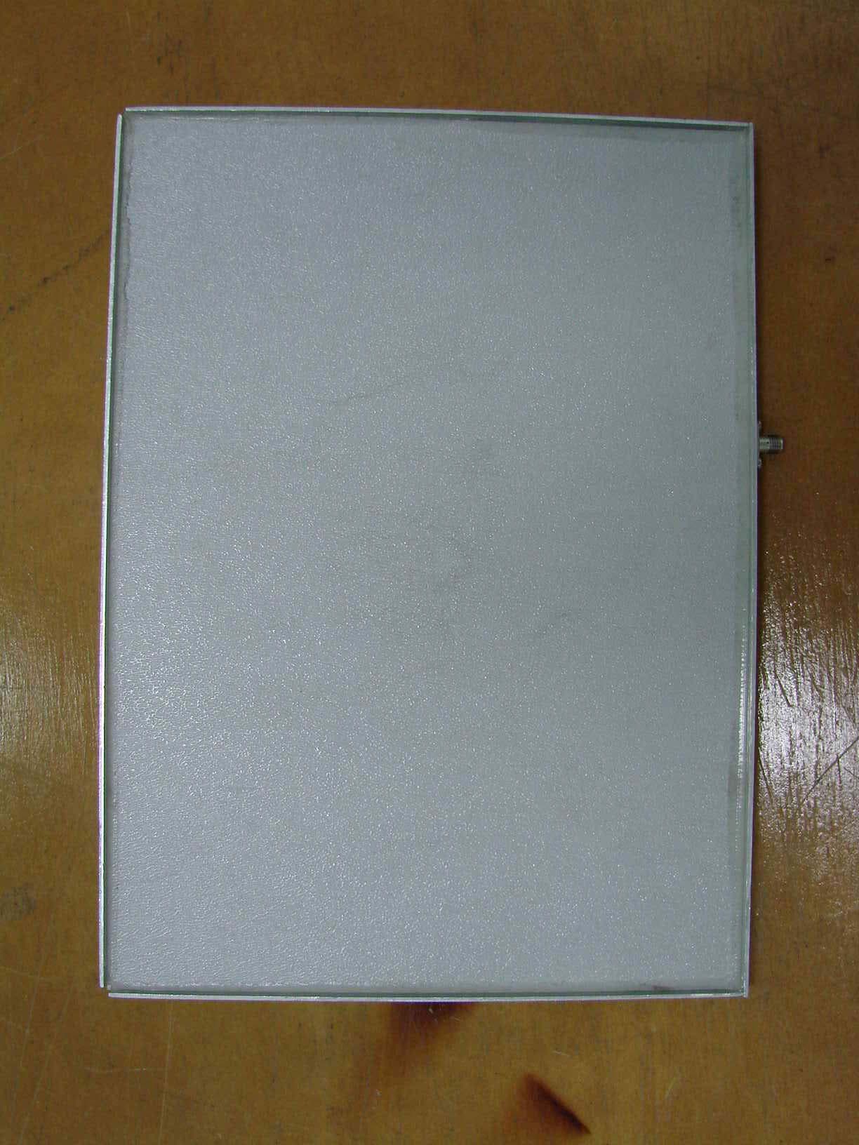
FCC ID.: SQD-6220APU-ABG File No. : E05DR-047 ONETECH Testing & Evaluation Lab. Panel Antenna for 2 GHz FCC ID.: SQD-6220APU-ABG File No. : E05DR-047 ONETECH Testing & Evaluation Lab. Bidirectional Antenna for 2GHz Omni directional Antenna for 2 GHz FCC ID.: SQD-6220APU-ABG File No. : E05DR-047 ONETECH Testing & Evaluation Lab. Panel Antenna for 5 GHz FCC ID.: SQD-6220APU-ABG File No. : E05DR-047 ONETECH Testing & Evaluation Lab. FCC ID.: SQD-6220APU-ABG File No. : E05DR-047 ONETECH Testing & Evaluation Lab.
ID Label/Location Info
FCC ID.: SQD-6220APU-ABG File No.: E05DR-047 ONETECH Testing & Evaluation Lab. IDENTIFICATION LABEL: PROPOSED FCC ID LABEL The label included following statement will be attached on the bottom side of product. This device complies with Part 15 of the FCC Rules. Operation is subject to the following two conditions: (1) this device may not cause harmful interference, and (2) this device must accept any interference received, including interference that may cause undesired operations. Made in Korea FCC ID : SQD-6220APU-ABG FCC ID AREA
Internal Photos
FCC ID.: SQD-6220APU-ABG File No. : E05DR-047 ONETECH Testing & Evaluation Lab. FCC ID.: SQD-6220APU-ABG File No. : E05DR-047 ONETECH Testing & Evaluation Lab. FCC ID.: SQD-6220APU-ABG File No. : E05DR-047 ONETECH Testing & Evaluation Lab. FCC ID.: SQD-6220APU-ABG File No. : E05DR-047 ONETECH Testing & Evaluation Lab. FCC ID.: SQD-6220APU-ABG File No. : E05DR-047 ONETECH Testing & Evaluation Lab. FCC ID.: SQD-6220APU-ABG File No. : E05DR-047 ONETECH Testing & Evaluation Lab. FCC ID.: SQD-6220APU-ABG File No. : E05DR-047 ONETECH Testing & Evaluation Lab. FCC ID.: SQD-6220APU-ABG File No. : E05DR-047 ONETECH Testing & Evaluation Lab. FCC ID.: SQD-6220APU-ABG File No. : E05DR-047 ONETECH Testing & Evaluation Lab. FCC ID.: SQD-6220APU-ABG File No. : E05DR-047 ONETECH Testing & Evaluation Lab. FCC ID.: SQD-6220APU-ABG File No. : E05DR-047 ONETECH Testing & Evaluation Lab. FCC ID.: SQD-6220APU-ABG File No. : E05DR-047 ONETECH Testing & Evaluation Lab. FCC ID.: SQD-6220APU-ABG File No. : E05DR-047 ONETECH Testing & Evaluation Lab.
Test Report
FCC ID: MXF-M930907 Report No.: RF930909L111Issued: Sep. 20, 2004 FCC TEST REPORT REPORT NO.: RF930909L11 MODEL NO.: WMIA-123AG RECEIVED: Aug. 16, 2004 TESTED: Aug. 16 ~ Aug. 19, 2004 APPLICANT: Gemtek Technology Co., Ltd. ADDRESS: No.1, Jen Ai Road, Hsinchu lndustrial Park, Hukou Hsinchu 303, Taiwan, R.O.C. ISSUED BY: Advance Data Technology Corporation LAB ADDRESS: 47 14th Ling, Chia Pau Tsuen, Lin Kou Hsiang 244, Taipei Hsien, Taiwan, R.O.C. TEST LOCATION: No. 19, Hwa Ya 2nd Rd., Wen Hwa Tsuen, Kwei Shan Hsiang, Taoyuan Hsien 333, Taiwan, R.O.C. This test report consists of 173 pages in total. It may be duplicated completely for legal use with the approval of the applicant. It should not be reproduced except in full, without the written approval of our laboratory. The client should not use it to claim product endorsement by CNLA, A2LA or any government agencies. The test results in the report only apply to the tested sample. 0528 ILAC MRA FCC ID: MXF-M930907 Report No.: RF930909L112Issued: Sep. 20, 2004 Table of Contents 1.CERTIFICATION ......................................................................................... 5 2.SUMMARY OF TEST RESULTS................................................................. 6 2.1 MEASUREMENT UNCERTAINTY............................................................... 8 3.GENERAL INFORMATION ......................................................................... 9 3.1GENERAL DESCRIPTION OF EUT ........................................................... 9 3.2DESCRIPTION OF TEST MODES ........................................................... 10 3.3GENERAL DESCRIPTION OF APPLIED STANDARDS ........................... 11 3.4DESCRIPTION OF SUPPORT UNITS...................................................... 12 3.5CONFIGURATION OF SYSTEM UNDER TEST....................................... 12 4.TEST TYPES AND RESULTS (FOR PART 802.11b & 802.11g) ............... 13 4.1CONDUCTED EMISSION MEASUREMENT ............................................ 13 4.1.1LIMITS OF CONDUCTED EMISSION MEASUREMENT ......................... 13 4.1.2TEST INSTRUMENTS .............................................................................. 13 4.1.3TEST PROCEDURES............................................................................... 14 4.1.4DEVIATION FROM TEST STANDARD ..................................................... 14 4.1.5TEST SETUP ............................................................................................ 15 4.1.6EUT OPERATING CONDITIONS.............................................................. 15 4.1.7TEST RESULTS........................................................................................ 16 4.2RADIATED EMISSION MEASUREMENT ................................................. 22 4.2.1LIMITS OF RADIATED EMISSION MEASUREMENT .............................. 22 4.2.2TEST INSTRUMENTS .............................................................................. 23 4.2.3TEST PROCEDURES............................................................................... 24 4.2.4DEVIATION FROM TEST STANDARD ..................................................... 24 4.2.5TEST SETUP ............................................................................................ 25 4.2.6EUT OPERATING CONDITIONS.............................................................. 25 4.2.7TEST RESULTS........................................................................................ 26 4.36dB BANDWIDTH MEASUREMENT ........................................................ 35 4.3.1LIMITS OF 6dB BANDWIDTH MEASUREMENT...................................... 35 4.3.2TEST INSTRUMENTS .............................................................................. 35 4.3.3TEST PROCEDURE ................................................................................. 35 4.3.4DEVIATION FROM TEST STANDARD ..................................................... 36 4.3.5TEST SETUP ............................................................................................ 36 4.3.6EUT OPERATING CONDITIONS.............................................................. 36 4.3.7TEST RESULTS........................................................................................ 37 4.4MAXIMUM PEAK OUTPUT POWER ........................................................ 47 4.4.1LIMITS OF MAXIMUM PEAK OUTPUT POWER MEASUREMENT ......... 47 4.4.2INSTRUMENTS........................................................................................ 47 4.4.3TEST PROCEDURES............................................................................... 48 4.4.4TEST SETUP ............................................................................................ 48 4.4.5EUT OPERATING CONDITIONS.............................................................. 48 4.4.6TEST RESULTS........................................................................................ 49 FCC ID: MXF-M930907 Report No.: RF930909L113Issued: Sep. 20, 2004 4.5POWER SPECTRAL DENSITY MEASUREMENT.................................... 50 4.5.1LIMITS OF POWER SPECTRAL DENSITY MEASUREMENT ................. 50 4.5.2TEST INSTRUMENTS .............................................................................. 50 4.5.3TEST PROCEDURE ................................................................................. 51 4.5.4DEVIATION FROM TEST STANDARD ..................................................... 51 4.5.5TEST SETUP ............................................................................................ 51 4.5.6EUT OPERATING CONDITION ................................................................ 51 4.5.7TEST RESULTS........................................................................................ 52 4.6BAND EDGES MEASUREMENT.............................................................. 62 4.6.1LIMITS OF BAND EDGES MEASUREMENT........................................... 62 4.6.2TEST INSTRUMENTS ...................…
Text truncated - open the document above for the full version.
Test Report
Page 1 of 58 FCC ID. : SQD-6220APU-ABG File No. : E05DR-047 It should not be reproduced except in full, without the written approval of ONETECH. EMC-007(Rev.0) HEAD OFFICE : #505 SK APT. Factory 223-28, Sangdaewon 1 Dong, Jungwon-Gu, Seongnam-City, Kyunggi-Do, 462-121, Korea (TEL: 82-31-746-8500 FAX: 82-31-746-8700) EMC Testing Dept : 426-1 Daessangryung-Ri, Chowol-Myun, Kwangju-Kun, Kyunggi-Do 464-860 Korea. (TEL: 82-31-765-8289 FAX: 82-31-766-2904) ELECTROMAGNETIC EMISSION C OMPLIANCE REPORT FOR LOW-POWER, NON-LICENSED TRANSMITTER Test report file number : E05DR-047 Applicant : M T I C o . , L t d . Address : 166-10 Garak-dong, Songpa-gu, Seoul Korea Manufacturer : M T I C o . , L t d . Address : 166-10 Garak-dong, Songpa-gu, Seoul Korea Type of Equipment : WLAN Cable Access Point FCC ID. : SQD-6220APU-ABG Model Name : WLAN Cable Access Point 6220-APU Serial number : None Total page of Report : 58 pages (including this page) Date of Incoming : December 22, 2005 Date of issue : November 7, 2005 SUMMARY The equipment complies with the regulation; FCC Part 15 Subpart C Section 15.247 and Subpart E. This test report only contains the result of a single…
Text truncated - open the document above for the full version.
Contact Information
Applicant
Ho Young Lee(MANAGER)
Test Firm
ONETECH Corp.Gea-Won Lee
Technical Specifications
| # | Rule Parts | Frequency Range | Power Output |
|---|---|---|---|
| 1 | 15C | 2.41 GHz - 2.46 GHz | 42.00 mW |
Other Applications from MTI Co., Ltd.
SQD-APU11B01POE
Jul 25, 2007Access Point Unit
Equipment Class
DTS - Digital Transmission System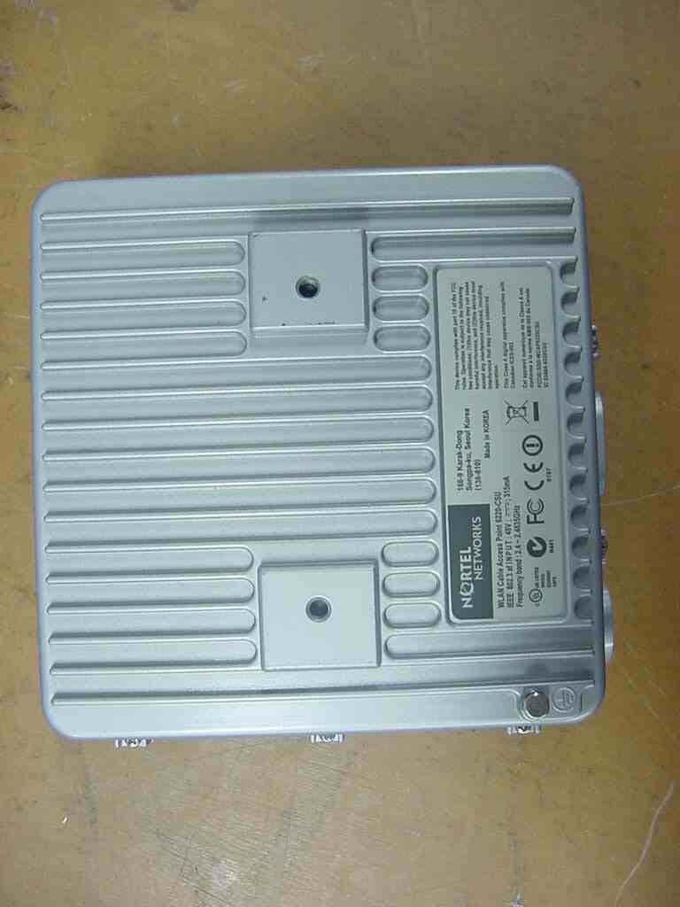
SQD-6220CSU-ABG
Nov 17, 2005WLAN Cable Access Point 6220
Equipment Class
DTS - Digital Transmission System
SQD-WCAP6220CSU
Dec 21, 2004WiFi Transceiver
Equipment Class
DTS - Digital Transmission System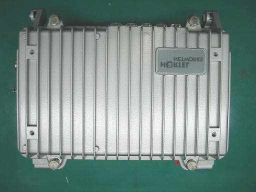
SQD-WCAP6220APU
Dec 18, 2004WiFi transceiver
Equipment Class
DTS - Digital Transmission System