SQD-WCAP6220CSUWiFi Transceiver
MTI Co., Ltd.
Click to zoom
Application Details
- Equipment Class
- DTS - Digital Transmission System
- Date of Grant
- Dec 21, 2004
- Application Purpose
- Original Equipment
- Date of Application
- Dec 21, 2004
- Equipment Note
- WiFi Transceiver
- Frequency Range
- 2412.00000000 - 2462.00000000
- Company
- MTI Co., Ltd.
- Country
- South Korea
Documents & Files
Document Text
Text extracted from the exhibit documents filed with the FCC. Open a document above to read the original.
Users Manual
Nortel Networks WLAN Cable Access Point 6220 User Guide Preliminary Release 1.0 Issue 2 Nov 2004 What’s inside? About this document Overview Planning your WLAN network Installation Configuration Administration Troubleshooting Appendix NTPM99CA 2 Copyright © 2004 Nortel Networks All rights reserved. July 2004. No part of this publication may be reproduced, stored in a retrieval system, or transmitted in any form or by any means, whether electronic, mechanical, photocopying, recording or otherwise without the prior writing of the publisher. Nortel Networks and the Nortel Networks logo are trademarks of Nortel Networks, Inc. Multi-Region Product Documentation This document may describe features that are not available in your region due to local regulations. Compliances Federal Communication Commission Interference Statement This equipment has been tested and found to comply with the limits for a Class B digital device, pursuant to Part 15 of the FCC Rules. These limits are designed to provide reasonable protection against harmful interference in a residential installation. This equipment generates uses and can radiate radio frequency energy and, if not installed and used in accordance with instructions, may cause harmful and, if not installed and used in accordance with instructions, may cause harmful interference to radio communications. However, there is no guarantee that the interference will not occur in a particular installation. If this equipment does cause harmful interference to radio or television reception, which can be determined by turning the equipment off and on, the user is encouraged to try to correct the interference by one or more of the following measures: . • Reorient the receiving antenna . • Increase the separation between the equipment and receiver . • Connect the equipment into an outlet on a circuit different from that to which the receiver is connected . • Consult the dealer or an experienced radio/TV technician for help FCC Caution: To assure continued compliance, (example - use only shielded interface cables when connecting to computer or peripheral devices). Any changes or modifications not expressly approved by the party responsible for compliance could void the user’s authority to operate this equipment. This device complies with Part 15 of the FCC Rules. Operation is subject to the following two conditions: (1) This device may not cause harmful interference, and (2) this device must accept any interference received, including interference that may cause undesired operation. When installing the unit, choose a location that provides a minimum separation of 20 cm from all persons during normal operation. The transmitted power of the APU and CSU does not exceed 36 dBm. 3 Publication history August 2004 Issue 1. Issued for WLAN Cable Access Point 6220 Release 1 November 2004 Issue 2. Issued for WLAN Cable Access Point 6220 Release 1 4 Contents ABOUT THIS DOCUMENT 5 OVERVIEW 13 I NTRODUCTION 13 P RODUCT DESCRIPTION 15 APU (ACCESS POINT UNIT) 17 CSU (CORPORATE SERVICE UNIT) 22 PLANNING YOUR WLAN NETWORK 27 S ITE SURVEY & PLANNING 28 W IRELESS NETWORK PLANNING 29 INSTALLATION 31 APU INSTALLATION & CONFIGURATION 34 P ROCEDURE 1-1 34 P ROCEDURE 1-2 35 P ROCEDURE 1-3 40 P ROCEDURE 1-4 41 P ROCEDURE 1-5 43 P ROCEDURE 1-6 50 P ROCEDURE 1-7 51 P ROCEDURE 1-8 53 CSU INSTALLATION & CONFIGURATION 55 P ROCEDURE 2-1 56 P ROCEDURE 2-2 58 CONFIGURATION 61 S OFTWARE INSTALLATION (AP CONFIGURATOR) 62 P ROCEDURE 3-1 64 P ROCEDURE 3-2 69 P ROCEDURE 3-3 75 P ROCEDURE 3-4 84 P ROCEDURE 3-5 88 P ROCEDURE 3-6 123 ADMINISTRATION 165 S AVE CONFIGURATION 166 L OAD NEW CONFIGURATION 167 L OAD NEW LICENSE 168 TROUBLESHOOTING 175 5 WLAN Cable Access Point 6220 NTPM99CA Rel 1.0 Issue 2 Nov 2004 APPENDIX A. SPECIFICATION 182 APPENDIX B. DOCSIS SPECIFICATION 187 APPENDIX C. ANTENNA TYPE 189 NTA.2407 PANEL ANTENNA 189 NTA.2412 BIDIRECTIONAL ANTENNA 190 NTA.2400 OMNI DIRECTIONAL ANTENNA 191 ET-PR12 BUILT-IN PANEL ANTENNA 192 APPENDIX D. ENCLOSURE DIMENSION 193 APPENDIX E. SITE SURVEY 195 APPENDIX F. WIRELESS NETWORK PLANNING 206 6 About this document This document describes the system features used in the WLAN Cable Access Point 6220 Release 1.0 Product. Topics covered include the following: • Overview Introduction Product Description APU (Access Point Unit) CSU (Corporate Services Unit) • System Planning Site Survey & Planning Wireless Network Designing • Installation APU Hardware Installation CSU Hardware Installation • Configuration APU in Hot Spot Mode (802.11b) APU in Secure Data Mode (P2P, P2M) CSU in Secure Data Mode (P2P, P2M) Testing Connection between APU and CSU • Advanced Configuration System Administration Tasks Save configuration Edit configuration Load new configuration Upload new license • Troubleshooting 7 WLAN Cable Access Point 6220 NTPM99CA Rel 1.0 Issue 2 Nov 2004 Audience The intended audience for this document includes: • Installers • Technicians • Nnetwork planners • Network & system engineers • Network administrators List of Abbreviations AP Access Point APU Access Point Unit ARP Address Resolution Protocol BPDU Bridge Protocol Data Unit BPSK Binary Phase-Shift Keying CATV Community Antenna Television CM Cable Modem CMTS Cable Modem Termination System CPE Customer Premises Equipment CSU Corporate Service Unit DBPSK Differential Binary Phase-Shift Keying DHCP Dynamic Host Configuration Protocol DOCSIS Data Over Cable Service Interface Specifications DQPSK Differential Quadrature Phase Shift Keying DVM Digital Volt Ohm Meter EAP Extensible Authentication Protocol EIRP Equivalent Isotropic Radiated Power EMI Electromagnetic Interference FCC Federal Communications Commission FCS Frame Check Sequence FTP File Transfer Protocol HFC Hybrid Fiber Coax ICMP Internet Control Message Protocol IEEE Institute of Electrical and Electronics Engineers ISM Industrial Scientific and Medical equipment ISP Internet Service Provider ITU International Telecommunication Union LOS Line of Sight MA…
Text truncated - open the document above for the full version.
Users Manual
103 WLAN Cable Access Point 6220 NTPM99CA Rel 1.0 Issue 2 Nov 2004 Figure 4-38 Hotspot Mode Advanced Setup window Channel/Frequency-- Select the channel and frequency for the remote device from the drop-down list. See Frequency Channels for a more detailed explanation of the frequency channels. Radio Transmit Rate-- Select the radio bit rate used to transmit. Your choices are: Auto-select (IEEE 802.11 only) Low (1 Mbps) Standard (2 Mbps) Medium (5.5 Mbps) High (11 Mbps) Multicast Rate-- Select one of the following values: 1 Mbps 2 Mbps 5.5 Mbps 11 Mbps Note that for data communication with wireless clients in its vicinity, the 802.11 device is able to determine the appropriate Transmit Rate for each client individually. 104 WLAN Cable Access Point 6220 NTPM99CA Rel 1.0 Issue 2 Nov 2004 However, for "anonymous data traffic" such as Multicast messages that must be transmitted to all stations simultaneously, the LAN Administrator must identify the correct Multicast Rate. Warning: Selecting the 5.5 Mbits/sec or 11 Mbits/sec values in network environments that do not satisfy these requirements may result in Multicast messages getting lost. Enable RTS/CTS - Select this checkbox to enable the Medium Reservation mechanism. When you enable Medium Reservation, the APU will use the Request to Send/Clear to Send (RTS/CTS) protocol to control wireless data transmissions, based on the length of the data frame that is to be transmitted. RTS/CTS Threshold-- Enter a Medium Reservation Threshold value. Valid values are any decimal value in the range of 0 to 2347. The default value of 2347 indicates that Medium Reservation is disabled. Note: Most vendors recommend using a threshold of around 500. DTIM Period-- The Delivery Traffic Indication Map (DTIM) parameter influences the handling of Multicast messages that need to be transmitted to the wireless medium. Valid values are any digit in the range of 1 through 65535. The recommended value is 1. Note that the default value of "0" indicates the default used by the manufacturer of the radio card, not "0" milliseconds. Distance between access points—This selection impacts the multicast rate. ALL stations connected to an AP need to receive broadcasts/ multicasts or some protocols (e.g. IP ARP) will not work, therefore, the distance between the multiple AP multicasts without negatively impacting performance. The value set (Small, Medium, Large) should be the value that guarantees that all stations will receive the broadcasts. The following table explains the relationship between these two fields: Multicast Rate Then Set Distance Between APs to ... 1 Mbps Large 2 Mbps Medium 5.5 Mbps Medium 11 Mbps Small 105 WLAN Cable Access Point 6220 NTPM99CA Rel 1.0 Issue 2 Nov 2004 802.11b Security Setup Clicking the Security button on the 802.11b Setup screen displays the 802,11b Security Setup screen, which allows you to set up security for your 802.11b devices. Note that the fields shown in the screenshot below will vary depending on the version of the Configurator you are using and the options contained in the .bin file. The screen below shows all available options. Figure 4-39 802.11 Security Setup window Disable WEP Encryption-- Select this button if you wish to disable Wired Equivalent Privacy (WEP) encryption. If you are not concerned about security (for example, home users using this device only to browse the Internet), and if you are not concerned your AP is used by others, then select this checkbox. Note: For simple security, you can disable WEP encryption and select the Closed Wireless System checkbox. Static WEP Keys Only-- Select this button if you wish to enter Wired Equivalent Privacy (WEP) keys identically on each access point/station and Secure Data Mode unit in the network. When you select this button, the four Static EP Encryption key fields are enabled on the right side of the screen. 106 WLAN Cable Access Point 6220 NTPM99CA Rel 1.0 Issue 2 Nov 2004 802.1x Auto WEP Key Generation-- Select this option if you wish to automatically create Wired Equivalent Privacy (WEP) keys using the 802.1x protocol. Selecting this option prevents you from creating static WEP keys. 802.1x & Static WEP Mixed Mode-- Select this option if you wish to automatically create Wired Equivalent Privacy (WEP) keys using the 802.1x protocol and also allow static keys. Deny Non-Encrypted Data-- Select this checkbox if you want to deny all received data that is not encrypted. When this checkbox is selected, any packet received that is not encrypted using one of the four WEP Encryption keys listed above will be dropped. When this checkbox is not selected, unencrypted packets will be accepted and/or forwarded. Warning: You should always select this checkbox if WEP is enabled in any form. If disabled, clients without WEP can access your network! Distribute WEP Keys-- If auto key generation is done in any form (auto-only or mixed mode), then the keys must be distributed to the stations. If you have 802.1x enabled on the interface, and STATIC generation ONLY, then the statically defined keys can still be distributed to 802.1x stations. However, if you do not have 802.1x, you cannot distribute WEP keys; and you must use Static keys and enter them manually. Regenerate New WEP Keys Every n Minutes-- When generating keys, change them every n minutes and send them to the access point/station. Note: This option is only available for 802.1x devices. Note: This option only applies if you have selected Auto WEP Key Generation. Use n-bit WEP Keys-- Select either 64-bit (silver) or 128-bit (gold) encryption keys. The higher bit count provides somewhat higher security. Static WEP Encryption Keys-- If you use static encryption keys, you must enter each key in the Static WEP Encryption Keys fields. Note that these keys must be entered identically on each access point/station and Secure Data Mode unit in the network. Encrypt Data Transmission Using Key n-- Enter the key number that should…
Text truncated - open the document above for the full version.
Cover Letter(s)
MTI Co., LTD 166-10 Karak-dong, Songpa-ku Seoul, Korea 138-810 Tel : +82-2-421-4042 Fax: +82-2-421-4043 URL: www.mtico.co.kr Date 15 th September, 2004 American Telecommunications Certification Body, Inc. 6731 Whittier Avenue Suite C110 McLean, VA 22101 To Whom It May Concern: Please be advised that MTI Co., Ltd authorizes the Solectron Technical Centre to act on our behalf, until otherwise notified, for applications submitted to American Telecommunications Certification Body, Inc. (ATCB). We certify that we are not subject to denial of federal benefits, that includes FCC benefits, pursuant to Section 5301 of the Anti-Drug Abuse ACT of 1988, U.S.C. 862. Further, no party, as defined in 47 CFR 1.2002(b), to the application is subject to denial of federal benefits, that includes FCC benefits. Thank you for your attention to this matter. Hong Sup Byun Director MTI Co., Ltd Product Engineering and QC/QA Dept.
Cover Letter(s)
Solectron Technical Centre 21 Richardson Side rd Kanata ON K2K 2C1 · Canada Tel 613 271-5322 Fax 613 271-2581 http://www.solectrontechnicalctr.com/ December 9, 2003 Denis Lalonde Radio Compliance Discipline Leader American TCB, Inc. 6731 Whittier Avenue Suite C110 McLean, VA 22101 Re: WCAP6220CSU Dear Sir or Madam: MTI Co., LTD requests, pursuant to 47 CFR 0.457 and 0.459 of the commission's rules, that the following items be held CONFIDENTIAL due to their proprietary nature. MTI Co., LTD considers this leading edge technology developed by MTI and its partners and being new technology, would not want to make this information available to its competitors. Exhibit 1. Schematics and Parts list 2. Block Diagrams Please call me or write if you have any questions or comments. Regards, Denis Lalonde email: [email protected] Solectron Technical Centre
Cover Letter(s)
Solectron Technical Centre 21 Richardson Side rd Kanata ON K2K 2C1 · Canada Tel 613 271-5322 Fax 613 271-2581 http://www.solectrontechnicalctr.com/ December 9, 2003 Denis Lalonde Radio Compliance Discipline Leader American TCB, Inc. 6731 Whittier Avenue Suite C110 McLean, VA 22101 Re: WCAP6220CSU (Short Term Confidentiality) Dear Sir or Madam: MTI Co., LTD requests, pursuant to 47 CFR 0.457 and 0.459 of the commission's rules, that the following items be temporarily held CONFIDENTIAL due to their proprietary nature. MTI Co., LTD considers this leading edge technology developed by MTI and its partners and being new technology, would not want to make this information available to its competitors. Exhibit 1. Internal Pictures Please call me or write if you have any questions or comments. Regards, Denis Lalonde email: [email protected] Solectron Technical Centre
Cover Letter(s)
Solectron Technical Centre 21 Richardson Side rd Kanata ON K2K 2C1 · Canada Tel 613 271-5322 Fax 613 271-2581 http://www.solectrontechnicalctr.com/ November 26, 2004 Denis Lalonde Radio Compliance Discipline Leader American TCB, Inc. 6731 Whittier Avenue Suite C110 McLean, VA 22101 Re: FCCID: SQD-WCAP6220CSU & IC:5340A-6220CSU Dear Sir or Madam: This is a FCC Part 15 and Industry Canada RSS-210 Original Equipment application for the MTI Co. WLAN 6220 Corporate Service Unit. It operates between 2412 and 2462 MHz. The FCCID of this equipment is SQD-WCAP6220CSU and the Industry Canada certification number is 5340A-6220CSU. Please call me or write if you have any questions or comments. Regards, Denis Lalonde email: [email protected] Solectron Technical Centre
External Photos
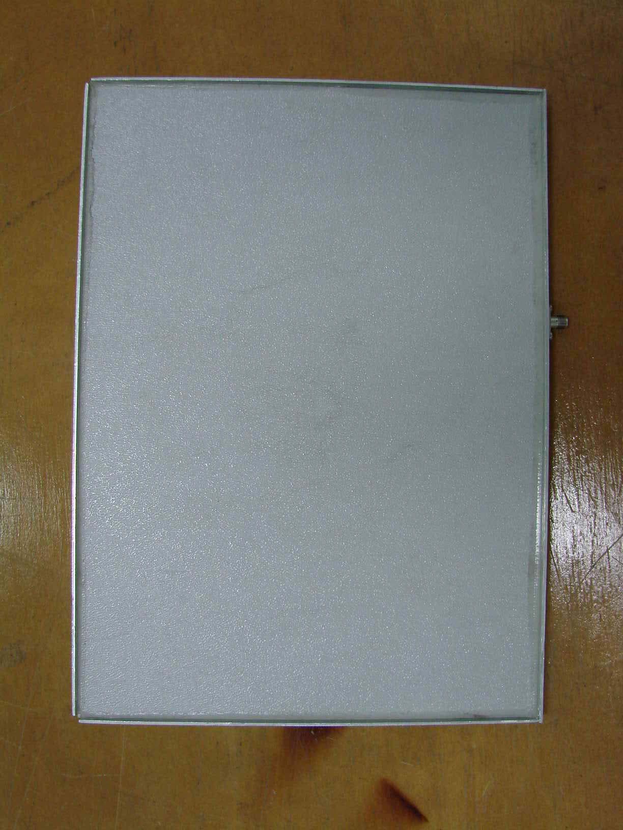
Front view Rear view
ID Label/Location Info
Label and Location
Internal Photos
Internal view of PCBs Antenna Connector Component side of power supply board Secondary side of power supply board Component side of Access Point PCB Secondary side of Access Point board Component and secondary side of Radio module WLAN Radio PCB (with shield covers removed)
Operational Description
13 Overview Introduction This document describes the system features used in the WLAN Cable Access Point 6220 Release 1.0 Product. The Wireless LAN Cable Access Point 6220 is an outdoor hardened, strand-mountable access point solution designed to extend the reach of the cable operators’ hybrid fiber coax network utilizing wireless technologies from existing rights of ways. This solution from Nortel Networks provides cable operators a fast, low-cost alternative for delivering service to new customers by eliminating the time, permits, and construction costs associated with extending aerial or buried drops. The WLAN Cable Access Point 6220 solution provides : Flexible service platform The WLAN Cable Access Point 6220 is a flexible service platform giving cable operators the ability to offer many different wireless services such as Public Hot Spots and Commercial High Speed Data services. Standard Compliance and Interoperability The WLAN Cable Access Point 6220 utilizes standard-compliant DOCSIS TM cable modems, thus ensuring interoperability with the existing cable network. Wireless access is accomplished using industry- standard IEEE 802.11 radios approved by government regulatory agencies for use in “unlicensed” ISM frequencies. 14 WLAN Cable Access Point 6220 NTPM99CA Rel 1.0 Issue 1 Aug 2004 Security Security is of the highest importance when delivering wireless services. The WLAN Cable Access Point 6220 adheres to industry standards for 802.11 devices and augments those standards with additional security features designed to provide both the cable operator and the end-user maximum protection. Performance optimization via multiple antenna options Nortel Networks provides antenna options specifically engineered to enable the WLAN Cable Access Point 6220 to achieve peak link performance in Line of Sight (LOS) and Near LOS applications. Ease of installation Designed for simple, fast installation by professional technicians, the WLAN Cable Access Point 6220 is installed in a simple three-step procedure: lock down strand clamps, connect power via coax drop, and attach and align antenna for service optimization Figure 1-1 WLAN Cable Access Point 6220 Service Concept Diagram 15 WLAN Cable Access Point 6220 NTPM99CA Rel 1.0 Issue 1 Aug 2004 Product Description Table 1-1 WLAN Cable Access Point 6220 Products No. PEC Description 1 NTPM99AC APU, 2.4G,A/B/G RADIO, CM 2 NTPM99AE APU, 2.4G,FP ANTENNA, 14dB gain 3 NTPM99AF APU, 2.4G,OMNI ANTENNA, 7dB gain 4 NTPM99AP APU, 2.4G,BI-DIRECTIONAL ANTENNA, 9dB Peak 5 NTPM99AE APU Antenna Mounting Kit / Tool 6 NTPM99CB R1.0 WLAN6220 CAP DOC,CD 7 NTPM99DA R1.0 WLAN6220 CAP SOFTWARE, CD 8 NTPM99CA R1.0 WLAN6220 CAP DOC,PAPER 9 NTPM99BC CSU, 2.4G,B RADIO, Flat Panel 10 NTPM99EG CSU Mounting Kit / Tool Figure 1-2 WLAN Cable Access Point 6220 APU Package Components Figure 1-3 WLAN Cable Access Point 6220 CSU Package Components 21 WLAN Cable Access Point 6220 NTPM99CA Rel 1.0 Issue 1 Aug 2004 CSU(Corporate Service Unit) The following is a list of WLAN Cable Access Point 6220 CSU features: Enclosure has a POE connection interface and a DC Power Adapter Jack at the bottom of CSU. Operation Power & Data Traffic are mixed at POE Injector and supplied to the Ethernet Port on CSU through CAT5 Cable. Basically, two kinds of mounting types are available for CSU, such as a pole mounting and wall mounting at house or tall building, but in case of wall mounting, another optional bracket kit will be needed for installation. The antennas is basically Flat Panel type which is built-in CSU body and protected by a plastic material RADOM. WLAN AP support the secure mode connection which mean that wireless traffic from APU and CSU is not scanned and detected by a conventional sniffing program like ‘Netstumbler’. 22 WLAN Cable Access Point 6220 NTPM99CA Rel 1.0 Issue 1 Aug 2004 Figure 1-9 WLAN Cable Access Point 6220 CSU (Bottom) Figure 1-10 WLAN Cable Access Point 6220 CSU (Front) 23 WLAN Cable Access Point 6220 NTPM99CA Rel 1.0 Issue 1 Aug 2004 Figure 1-11 (Back) WLAN Cable Access Point 6220 CSU Figure 1-12 WLAN Cable Access Point 6220 CSU 24 WLAN Cable Access Point 6220 NTPM99CA Rel 1.0 Issue 1 Aug 2004 Table 1-3. Modules and Connectors (CSU) Item Label Description & Function 1 Antenna Radome Protective Cover designed to contain a built-in antenna 2 Enclosure(Body) Housing Integrated with an Antenna Case Assembly 3 Logo Panel Location for Nortel networks Logo 4 DC Power Socket Provide DC power(12V) from AC-DC Adaptor to CSU 5 Ethernet Port(POE) Provide data connection between CSU and POE Injector or LAN Switch 6 EMI Cap EMI Cap designed to prevent CSU from interfering to or from other devices Additionally, provide water proof feature accompanied by sealing tape. 7 Ground Point Location for grounding the enclosure to earth for protecting the product from damage 8 Label(Front) Location for attaching a product label which include S/N,PEC,MAC address and so on 9 Label(Back) Location for attaching a product label which include S/N,PEC,MAC address and so on 10 Access Point Mini-PCI type III Radio Card, System Board(Wi-Fi & Secure Mode TM ) 11 POE Splitter Power Module to divide Ethernet Signal and DC power combined signal from POE Injector 12 POE Injector Provide 802.3af based signal to CSU through Ethernet Port on CSU 13 Bracket Hole Bolt Hole for assembly of mounting bracket 14 Built-in Antenna 2.4GHz Radio Frequency Antenna (Flat Panel). 138 WLAN Cable Access Point 6220 NTPM99CA Rel 1.0 Issue 1 Aug 2004 Corporate service unit (CSU) General o Case: Aluminum alloy steel (Body), RADOME o Size: 180 (W) x 239 (L) x 81 (D) (mm) 7.08 (W) x 9.40 (L) x 3.19 (D) (inch) o Weight: 1.3 Kg / 2.8659 lbs o Elements: Access Point, POE Splitter, Built-in Antenna in CSU body, RADOME o Ports: POE Ethernet Port(RJ-45/CAT5), 12V DC Jack o Temperature: -40 ~ 65 ºC (Operating) o Power supply(Option): 802.3af compliant POE Injector(45V DC, 315 mA) o Power Consumption : MAX 10W (Current < 0.4A) Hardware Radio…
Text truncated - open the document above for the full version.
Parts List/Tune Up Info
Docu_No. Rev. 1.0.10 Date Depart. Officer Model CODE No Articles Vender P/N Vender Q'ty Note 1 AP Module AP6220-B4-R1-V1 MTI 1 2 WLAN Card Module MP-B-AG-00 USI 1 3 CSU Power Module AP-1206 Apro 1 4 CASE MWCSU-N0100 MTI 1 5 Antenna ET-PR12 EMC Tech 1 6 RF Assy Cable SMB-Hi-Mini-1 TMS Korea 1 2004. 11. 24. Wireless LAB #3 in R&D Center INYOUNG, LEE PARTS LIST Descriptions Based on STPC Elite Processor, Turbocell TM Mode WLAN CABLE ACCESS POINT 6220 CSU Aluminum Diecasting, With Bolt & Nut & Washer, & EthernetConnectorFreq. 2.4~2.4835GHz, 12dBi Gain, 35 X 35 mmU.FL-LP-068-A-130-SMB(M) ST (50ohm), 130mm, Hirose, WithTDK Ferrite Cores(RH4.2 X 9.2 X 1.2) & Rubber RingIEEE 802.11b, Mini PCI Type III, Agere Hermes II Chip SetAP Board Power & PoE PD Function MTI Co., Ltd. 1/7 Docu_No. Rev. 1.0.10 Date Depart. Officer Model CODE No Articles Vender P/N Vender Q'ty Note 1 PCB AP6220-B4-R1 CAC Tehc 1 2 IC CPU STPCE1HEBI ST 1 3 IC Logic IDT2305-1DCI IDT 1 4 IC Memory MT48LC2M32B2TG-7IT Micron 2 5 IC Memory M29W040B90K6 ST 1 6 IC Logic SN74HC273PWR TI 1 7 IC Sensor LM75CIMM-3 National 1 8 IC Supervisor LM3706XQBP-308 National 1 9 IC Fixed Reg. LP3962EMP(X)-2.5 National 1 10 IC Logic SN74AC245PW(R) TI 2 11 IC Logic SN74AC00PWR TI 1 12 IC Converter DP83815DUJB National 1 13 IC Interface LF8505R Delta 1 14 Connector Molex 53856-5018 Molex 1 15 Connector Molex 1318916 AMP 1 16 Connector Molex 68123-0611 Molex 1 DP83815DUJB 10/100 MB/S PCI CONTR BGA160LM3706 MPROCES SUPERV CKT 9L MICRO SMD74AC245 OCT BUS 3-OUT TRANCEIV TSSOP20 2004. 11. 24. Wireless LAB #3 in R&D Center PARTS LIST INYOUNG, LEE 74AC00 QUADRUPLE 2-IN NAND GATE TSSOP1474HC273PW OCTAL D-Flip Flop, TSSOP20x86 Processor, Upto 133MHz, PBGA, IND-TEMP3.3V Zero Delay CLK Buffer, 8-SOIC, IND-TEMPLM75 DIG TEMP SENSOR Mini SOIC SO-82MX32, SDRAM, TSOP-86, IND-TEMP4MBIT, FLASH, PLCC32, IND-TEMP WLAN CABLE ACCESS POINT 6220 CSU(AP Module) LP3962 2.5V POS REGULATOR SOT-223 Descriptions APU IV(MiniPCI type), 1.6 t, FR-4, 6L, 140x117, V1.0LF8505R 10/100 1-PORT XFORMER MOD SO-16PIN HEADER ASSY 50 POS SMT COMPACT FLASHPIN HEADER ASSY 124 POS SMT Mini PCI, 5.2mm HeightHeader TIN T/H, 6P(3X2), 2mm, Male, Vertical MTI Co., Ltd. 2/7 No Articles Vender P/N Vender Q'ty Note Descriptions 17 Connector Molex 68123-1411 Molex 1 18 Connector Molex 68123-1011 Molex 1 19 Connector Molex 68125-1621 Molex 1 20 Inductor Chip Bead BLM31PG121SN1B Murata 2 21 Inductor Chip Bead MI0603J680R-00 Steward 7 22 Crystal FPX143TR Fox 1 23 Crystal FoxSD/250F-20/TR Fox 1 24 Buzzer XCMT12F2403P KKE 1 25 Diode BAW56LT1 On Semi 1 26 Heat Sink TSC029006 TEI 1 27 Heat Sink 1308-13(B) Sink Tech 1 28 Tactile Switch KTP1138 KKE 1 29 TR MMBT3904 Fairchild 1 30 TR NDS351N Fairchild 2 31 Chip LED KPTB-1615ESGC King Bright 4 32 Chip LED KP-1608SGC King Bright 1 33 Capacitor Chip GRM1885C1H100JA01D Murata 1 34 Capacitor Chip GRM1885C1H150JA01D Murata 2 35 Capacitor Chip GRM188R71C104KA01 D Murata 41 Ceramic, 10pF, ±5%, 50V, C0G/NPO, 0603Ceramic, 15pF, ±5%, 50V, C0G/NPO, 0603Ceramic, 0.1uF, ±10%, 16V, X7R, 0603MMST3904 GEN PURP NPN TRANSISTOR SOT-23TN0200T 20V N-CHAN MOSFET SOT-23 TRBRPG1211 SMT RED/GREEN BI-COLOR LEDSMT 0603 GREEN CHIP LED12mm Piezo Buzzer(Rated Voltage : 3V)BAW56 COM-A SOT-23 (A1) DUAL DIODE TRHeader TIN T/H, 16P(2X8), 2.54mm, Male, Right AngleFER EMI Bead, 68ohm, 1AMP, 060325MHz, SMD, HC-4914.3MHz, SMD, FPX143FER Bead, 120ohm, 3AMP, 120630 X 30 mm, Heat SinkHeader TIN T/H, 14P(2X7), 2mm, Male, VerticalHeader TIN T/H, 10P(2X5), 2mm, Male, Vertical13 X 13 mm, Heat SinkSUBMINIATURE Vertical RAD SPST SWITCH, SMD type MTI Co., Ltd. 3/7 No Articles Vender P/N Vender Q'ty Note Descriptions 36 Capacitor Chip GRM188R71H103KA01 D Murata 29 37 Capacitor Chip GRM1885C1H270JA01D Murata 2 38 Capacitor Chip GRM188R71H222KA01 D Murata 4 39 Capacitor Chip GRM188R71H221KA01 D Murata 14 40 Capacitor Chip GRM188R71H471KA01 D Murata 12 41 Capacitor Chip GRM188R71H510KA01 D Murata 4 42 Capacitor 30GAD10 CERA- MITE/VISHAY 2 43 Capacitor Tantal TAJB336M010R AVX/KYOCERA 5 44 Capacitor Tantal TAJA106K006R AVX/KYOCERA 2 45 Capacitor Tantal TAJB226M010R AVX/KYOCERA 2 46 Capacitor Tantal TAJB107M006R AVX/KYOCERA 2 47 Resister Array Chip MNR14E5ABJ103 ROHM 5 48 Resister Array Chip EXB-V8V473JV PANASONIC 12 49 Resister Array Chip EXB-V8V511JV PANASONIC 2 50 Resister Array Chip EXB-V8V220JV PANASONIC 9 51 Resistor Chip ERJ-3GEYJ220V PANASONIC 7 52 Resistor Chip ERJ-3GEYJ472V PANASONIC 8 53 Resistor Chip MCR10EZHF9.31K ROHM 1 54 Resistor Chip ERJ-6GEYJ510V PANASONIC 4 Thick Film, 9.31kohm, ±1%, 1/8W, 0805Thick Film, 51ohm, ±5%, 1/8W, 0805Thick Film, 510ohm, ±5%, 0603, 4PThick Film, 22ohm, ±5%, 0603, 4PThick Film, 22ohm, ±5%, 1/16W, 0603Thick Film, 4.7kohm, ±5%, 1/16W, 0603Tantalum, 100uF, ±20%, 6.3V, 3528(CASE B)Thick Film, 10kohm, ±5%, 0603, 4PThick Film, 47kohm, ±5%, 0603, 4PTantalum, 22uF, ±20%, 10V, 3528(CASE B)RAD Leaded Ceramic, 1000pF, ±20%, 3kV, Z5UTantalum, 33uF, ±20%, 10V, 3528(CASE B)Ceramic, 470pF, ±10%, 50V, X7R, 0603Tantalum, 10uF, ±10%, 6.3V, 3216(CASE A)Ceramic, 27pF, ±5%, 50V, NPO, 0603Ceramic, 2200pF, ±10%, 50V, X7R, 0603Ceramic, 220pF, ±10%, 50V, X7R, 0603Ceramic, 51pF, ±10%, 50V, X7R, 0603Ceramic, 0.01uF, ±10%, 50V, X7R, 0603 MTI Co., Ltd. 4/7 No Articles Vender P/N Vender Q'ty Note Descriptions 55 Resistor Chip ERJ-6ENF75R0V PANASONIC 2 56 Resistor Chip ERJ-3EKF511V PANASONIC 1 57 Resistor Chip ERJ-3GEYJ100V PANASONIC 4 58 Resistor Chip ERJ-3GEYJ222V PANASONIC 1 59 Resistor Chip ERJ-3EKF1001V PANASONIC 5 60 Resistor Chip ERJ-3EKF1002V PANASONIC 5 61 Resistor Chip ERJ-3GEYJ330V PANASONIC 4 62 Resistor Chip ERJ-3GEJ473V PANASONIC 10 63 Resistor Chip MCR10EZHJ000 ROHM 2 64 Resistor Chip ERJ-3GEYJ000V PANASONIC 1 65 Resistor Chip ERJ-3GEYJ105V PANASONIC 1 66 Fuse BA-100-1A Save 2 67 Socket PLCC 32 SMD ShinHwa Tech 1 LDP + Lead Frame, 63V 1A, SMD. 0805PLCC32 Socket, 1.27mm, SMDThick Film, 33ohm, ±5%, 1/16W, 0603Thick Film, 47kohm, ±5%, 1/16W, 0603Thick Film, 1Mohm, ±5%, 1/10W, 0603Thick Film, 0ohm, …
Text truncated - open the document above for the full version.
RF Exposure Info
186 Appendix C. Antenna Type NTA.2407 Panel Antenna WLAN Cable Access Point 6220 NTPM99CA Rel 1.0 Issue 1 Oct. 2004 187 NTA.2412 Bidirectional Antenna WLAN Cable Access Point 6220 NTPM99CA Rel 1.0 Issue 1 Aug 2004 188 NTA.2400 Omni directional Antenna WLAN Cable Access Point 6220 NTPM99CA Rel 1.0 Issue 1 Oct. 2004 189 ET-PR12 Built-in Panel Antenna WLAN Cable Access Point 6220 NTPM99CA Rel 1.0 Issue 1 Aug 2004
RF Exposure Info
Solectron Design and Engineering 21 Richardson Side rd Kanata ON K2K 2C1 · Canada Tel 613 271-5322 Fax 613 271-2581 http://www.solectrontechnicalctr.com/ December 9, 2004 Denis Lalonde Radio Compliance Discipline Leader American TCB, Inc. 6731 Whittier Avenue Suite C110 McLean, VA 22101 Re: FCCID: SQD-WCAP6220CSU & IC:5340A-6220CSU Dear Sir or Madam: This is the FCC Part 15 and Industry Canada RSS-210 MPE report for the MTI Co. WLAN 6220 Corporate Service Unit. Test Specification The system was tested to the limits of the following requirement: Table 1: RF Exposure Requirement Requirement Part / Section FCC Part 1 1.1310 RSS-210 14. RSS-210 makes reference to the RSS-102 requirements. Limits The specification levels are listed in Table 2. Table 2: RF Exposure Limit Frequency Range (MHz) FCC and RSS 102 General Exposure Limit (mW/cm 2 ) 2412 to 2462 1.0 RF Exposure Evaluation Table 3 and Table 4 demonstrate the results of RF exposure calculations: Page 2 Table 3: EIRP Calculations Peak Power (W) ET-PR12 Antenna gain EIRP (W) 0.0195 (12.9 dBm) 15.8 (12 dBi) 0.308 (24.9 dBm) Table 4: RF Exposure Evaluation Power Density at 20 cm (mW/cm 2 ) FCC and Industry Canada RF Exposure limit (mW/cm 2 ) 0.061 1 The power density was calculated using the following equation. S = (P x G) / (4 x pi x R 2 ) where: S = power density (in appropriate units, e.g. mW/cm 2 ) P = power input to the antenna (in appropriate units, e.g., mW) G = power gain of the antenna in the direction of interest relative to an isotropic radiator R = distance to the center of radiation of the antenna (appropriate units, e.g., cm) Evaluation Conclusion and Attestation The MTI Co. WLAN 6220 Access Point Unit meets the FCC Part 15 and Industry Canada RSS 102 maximum permissible requirements. Please call me or write if you have any questions or comments. R…
Text truncated - open the document above for the full version.
Contact Information
Applicant
Ho Young Lee(MANAGER)
Technical Contact
Solectron Design and EngineeringDenis Lalonde
[email protected]613-271-5322
21 Richardson Side Road · Ontario · Canada
Test Firm
TUV SUD CANADA, INC.William (Mac) Elliott
[email protected]813-284-2736
Technical Specifications
| # | Rule Parts | Frequency Range | Power Output |
|---|---|---|---|
| 1 | 15C | 2.41 GHz - 2.46 GHz | 20.00 mW |
Other Applications from MTI Co., Ltd.
SQD-APU11B01POE
Jul 25, 2007Access Point Unit
Equipment Class
DTS - Digital Transmission System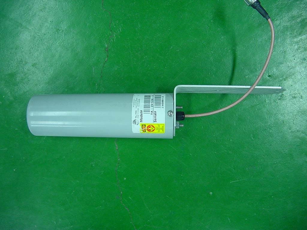
SQD-6220APU-ABG
Jan 17, 2006WLAN CATV Access Point
Equipment Class
DTS - Digital Transmission System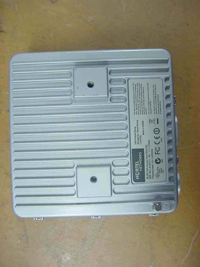
SQD-6220CSU-ABG
Nov 17, 2005WLAN Cable Access Point 6220
Equipment Class
DTS - Digital Transmission System
SQD-WCAP6220APU
Dec 18, 2004WiFi transceiver
Equipment Class
DTS - Digital Transmission System